Category Helicopter Test and Evaluation

Evaluating control forces

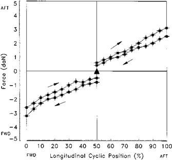
Measuring the force gradient for a control is achieved using either a spring balance or a force gauge placed at the relevant CR Point. The force is applied in a slowly increasing manner to note the precise force at which the control starts to move; this will give the value of the breakout force plus the static friction (B + F). Having overcome B + F, the standard convention is then to use only sufficient force to keep the control moving. The force required is recorded at regular intervals of displacement

image112

Fig. 5.2 Force/displacement plot: longitudinal cyclic stick.

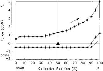
to allow the production of a force/displacement plot as shown in Fig. 5.2. When the limit of displacement has been reached the force is reduced gradually until the control moves back towards the trim point. Note on Fig. 5.2 that having reached full displacement the control will not start to move back towards the trim position until the force has been reduced by a value equal to twice the static friction. If a control friction device is fitted it is usually placed in the fully OFF position when measuring the forces. If there is no trim system then it is still necessary to measure and document the value of the sliding friction. An example of a collective force/displacement plot is shown in Fig. 5.3. Pilots are very sensitive to the value of B + F as the majority of control inputs are small being used to make minor adjustments to the helicopter’s flight path. If B + F is set too high it will make precise control difficult and some pilots deliberately fly holding a trim force during tasks such as instrument approaches to overcome this problem. On the other hand too weak a force will lead to inadvertent small control inputs due to vibration or turbulence. Where an adjustable friction device is fitted this is assessed to determine if it can be used to set precise amounts of friction. For obvious reasons it should not be possible to lock the control by setting excess friction.

The designer of the control system will set the value of the cyclic force gradient to allow the pilot to move the control rapidly, but at the same time sufficient force gradient must be provided to prevent unintentionally large inputs. In the case of aircraft with high cyclic control power the need to provide protection may predominate and the force gradient may be quite high. This will have a significant effect on handling qualities during manoeuvres where the control has to be moved faster than can be achieved with a beeper trim system, or where trimming is not desirable, such as during a flyaway from the hover following a single engine failure. In this case the need to

image113

Fig. 5.3 Force/displacement plot: collective lever.

overcome a high spring feel force will make the flyaway more difficult to achieve and may cause an excessive height loss. On the other hand too shallow a force gradient will also lead to problems with the pilot making excessively rapid inputs; the pilot may then feel constrained into making only gentle inputs to avoid this problem and thus may not achieve the full agility of the helicopter. It is also necessary to assess the maximum force that a beeper trim system can produce, known as the limit control force, to determine if the pilot could retain control with a trim runaway. Holding the control at one end of its available range and then trimming fully in the opposite direction stimulates this.

Where a force trim release button is fitted the sudden release of the force will often cause the control to ‘jump’ as the pilot changes the amount of force he is applying. In the case of the cyclic this is known as stick jump. To the pilot this can become irritating, as it is not possible to make small changes to the datum trim position. To test control jump, the control is displaced from the trim position, the release operated and the reaction of the control noted. The amount of displacement used for this test is a realistic amount that an operational pilot might employ before operating the release. After ground tests, an airborne assessment is made to determine if any control oscillations cause an undesirable aircraft response.

Associated with the force gradient tests are the determination of the centring characteristics. This is the tendency of the cyclic to return towards the trim point when any displacing force is removed. Positive centring indicates a return towards the trim point while absolute centring is achieved if the control returns precisely to the original trim position. When conducting this test the control is displaced from trim and then allowed to return slowly towards trim. Where centring is positive but not absolute there will be a trim control displacement band (TCDB). This occurs as a consequence of a weak breakout force that is insufficient to overcome sliding friction. If the cyclic is moved to any position within this band and released it will stay at that position.

The implications of a trim control displacement band will vary according to the flight task and will not always have a detrimental effect on aircraft control. For example, when instrument flying a large TCDB would make it difficult to control aircraft attitude but a small band would allow the pilot to make small attitude changes without having to re-trim. A small TCDB may also make hovering easier again by obviating the need to make constant trim inputs. It is important, however, to understand that a TCDB will have implications for AFCS functions which use cyclic position as an input. For example, an attitude command/attitude hold system would not return the aircraft to the original attitude after a pilot input if a TCDB was present. The TCDB can be reduced by reducing the amount of friction in the system or by increasing breakout force.

It should be remembered that force gradients are not always linear and sometimes soft stops are incorporated such as the intermediate and maximum pitch stops in the Aerospatiale AS 341 Gazelle collective control. These soft stops can be incorporated for a number of reasons such as cueing the pilot to the limit of the power-on collective lever movement or defining the surge-free range of lever displacement. The cueing properties of the stop and the force required to overcome it are assessed during manoeuvres that require large and rapid control movements. For example, if the force required to overcome a stop is too high it might have serious implications during an engine-off landing if it interfered with the application of collective pitch at touchdown.

Since harmonization of control forces is an important aspect that will affect the aircraft’s handling qualities, the force gradient in any axis should be matched with the breakout force. For instance, if there is a high breakout force and a shallow force gradient it will be difficult to make precise inputs which require the control to be moved through the trim point. This may make manoeuvres such as hovering and NOE flight difficult. Harmonization of the forces of all the flight controls and between the lateral and longitudinal axes of the cyclic is also important for good control. It is the pilot’s perception of harmony between the forces that is the important issue not necessarily the actual values. This is due to the physiology of the human body that makes it easier to generate higher forces with the legs than with the arms; similarly it is easier to push the cyclic to the left than pull it to the right. Specifications such as ADS-33E [5.2] encompass this idea of ‘perceived’ or ‘apparent’ harmony by merely stating that forces, displacements, and sensitivities… shall be compatible’, without specifying values. Where the control forces are poorly harmonized manoeuvring is more difficult particularly during manoeuvres that require extensive use of all controls such as pirouettes [5.2] or downwind quickstops.

Stability and Control Testing

5.1 ASSESSING FLIGHT CONTROL MECHANICAL CHARACTERISTICS

When evaluating control aspects of rotorcraft the first aspect to consider is the characteristics of the control system. As the pilot must control the swashplate through the flight controls a deficiency in their operation will affect all areas of flight. Even excellent aircraft handling qualities can be masked by poor flight control mechanical characteristics (FCMC). Testing can be divided into quantitative aspects which normally take place on the ground and qualitative aspects which are conducted in flight. As quantitative testing is concerned with the measurement of forces and displacements it can be conducted more easily and safely on the ground. For reversible systems, however, the amount of ground testing that can be undertaken is limited by the requirement to have the rotors turning and by the need to evaluate realistic flight forces. Qualitative testing is concerned with the effect that the control system characteristics have on the conduct of role tasks. This section will only cover conventional control systems with displacement controllers.

In any assessment that includes FCMC a comprehensive control reference system is defined. This establishes the test conditions in case the controls of an aircraft are modified at some stage subsequent to the assessment. The reference system records the range of movement for all the controls. As the distances through which controls move and the forces needed to move them vary depending on where the measurement is made, it is necessary to define this point which is termed the control reference point (CR Point). The definition is usually given in specification documents such as the Ministry of Defence Standard 00-970 [5.1]. Having defined the CR Point for each control the next stage is to determine a position within the throw of each control from which displacements are measured. The position is known as the control reference position (CR Posn). The CR Posn can be defined anywhere along the control throw although it is usual to set the position at the mid-point for the cyclic axes and the yaw pedals. The convention for the collective is to use the minimum pitch position. By measuring the distance to the cyclic CR Posn from three points on the aircraft structure it is possible to reference the control envelope to the cockpit as a whole. As the pedals and collective only move in one direction, or follow an arc, a single measurement normally suffices to define the location of the CR Posns for these types of controllers.

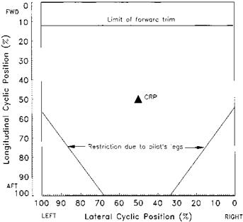
The cyclic control envelope is the area described by the maximum cyclic displacement (measured at the CR Point) in all directions. The envelope can only be measured fully with rotors stopped. Of course the assessment of the acceptability of the envelope can only be made in flight. Determining if the control envelope is satisfactory is not as simple as it may seem at first. If items within the cockpit restrict the range of control

image111

Fig. 5.1 Cyclic stick displacement envelope.

movement it is not necessarily a deficiency; it is only significant if the restriction is encountered during flight manoeuvres. Of course it is important that the pilot is able to reach the required envelope of all the controls from the normal seated position. A typical presentation of a cyclic envelope is shown in Fig. 5.1. The envelope may be affected by the operation of mechanical interlinks and is measured with the collective and yaw pedals at both ends of their displacement range. The position of the pilot’s seat can affect the amount of the envelope that can be used and this is placed in the most restrictive position – fully forward and normally fully up. Where the displacement that can be achieved using the trim system is less than the full displacement then this too is presented on the envelope plot. Problems are sometimes experienced with the envelopes of the other controls; for example, to lower the collective lever fully some pilots have to lean over to an uncomfortable degree. This highlights the importance of recording the assessing pilot’s anthropometric data and seating position.

Effect of airspeed on dynamic modes

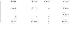
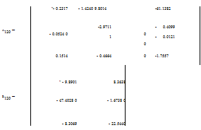
An estimate of the likely behaviour can be made by examining the aero-derivative and control matrices. Below are a set of matrices for three flight cases: hover, 60KTAS and 120KTAS. Note that the yaw angle response has been removed and that the state vector has been re-ordered to [v, p, ф, r]T.

Подпись:

Подпись: Ahov Подпись: - 0.0394 - 0.6653 9.7665 0.1365 - 0.0624 - 3.1111 0 - 0.0278 0 1 0 0.0837 0.0391 - 0.5046 0 - 0.3742

Подпись:" – 9.7060 5.6145"

– 47.0134 – 1.1236

Effect of airspeed on dynamic modes
Подпись: The dynamic modes can be described as: (1) Hover. The eigenvalues of the Ahov matrix are: - 0.0484 + 0.3835г, - 0.0484 - 0.3835г, - 0.2381, - 3.1898 These eigenvalues imply three stable modes, one second-order (oscillatory) response and two first-order responses. The second-order mode (LDO) has a natural frequency of 0.387rad/s giving an observed period of 15.4 s and a relative damping value of 0.125 (T1!2 of 14.3 s). The first-order responses have time constants of 4.20s (-0.2381) and 0.31 s (-3.1898). (2) 60 KIAS. The eigenvalues of the A60 matrix are:
Подпись: - 0.5329 + 1.7540г, - 0.5329 - 1.7540г, - 0.0508, - 3.1717

0 0 – 8.4807 – 15.1333

– 0.1320

0.9829

9.7929

-30.4417

– 0.0455

– 3.0478

0

– 0.2221

0

1

0

0.0535

0.1016

– 0.4899

0

– 1.1085

A60 —

Again these eigenvalues imply three stable modes. In this case the second-order mode has a natural frequency of 1.833 rad/s giving an observed period of 3.6 s and a relative damping value of 0.291 (T1/2 of 1.3 s). The first-order responses have time constants of 19.69s ( — 0.0508) and 0.32s ( — 3.1717).

(3) 120 KIAS. The eigenvalues of the A120 matrix are:

— 0.8882 + 2.9488г, — 0.8882 — 2.9488г, — 0.0528, — 3.1292

Here the second-order mode has a natural frequency of 3.08 rad/s giving an observed period of 2.1s and a relative damping value of 0.288 (T1/2 of 0.8 s). The first-order responses have time constants of 18.94s ( — 0.0528) and 0.32s ( — 3.1292).

Thus the Lateral/Directional Oscillation (LDO) is stable throughout the speed range although the period and damping of the oscillatory mode varies with airspeed. The helicopter would appear, therefore, dynamically stable to the pilot with the frequency increasing with airspeed. This result agrees with detailed analysis given above. Also, since the spiral mode is characterized by the first order mode with the longer time constant, note that for the example helicopter the mode is stable with the rate of convergence being greater at 120 KIAS than at 60 KIAS. The roll control response is, therefore, characterized by the other, shorter, first-order mode and for the example helicopter there appears to be very little change in this mode with airspeed.

4.11.7.1 Effect of increased roll damping

The effect of an increase in roll damping, achieved by a direct increase in the numerical value of the rolling moment due to roll rate (Lp), can be shown by increasing the appropriate value in the A matrix. Consider the 60 knot case discussed earlier: and suppose the value of Lp is increased from — 3.0478 to — 6.0956:

" — 0.1320

0.9829 9.7929

— 30.4417

— 0.0455

— 6.0956

0

— 0.2221

0

1

0

0.0535

0.1016

— 0.4899

0

— 1.1085_

" — 9.7054

5.7541

— 47.0742

— 1.1515

0

0

— 8.3750

— 15.5094

A60 —

B60 —

The effect of this change on the dynamic response can be seen from the change in the eigenvalues:

(1) Before. — 0.5329 + 1.7540i, — 0.5329 — 1.7540i, — 0.0508, — 3.1717, resulting in the following engineering parameters:

C — 0.291, mn — 1.833 rad/s, T1 — 19.69 and T2 — 0.32

(2) After. – 0.5892 + 1.7384г, – 0.5892 – 1.7384г, – 0.0183, – 6.1393, resulting in the following:

C = 0.321, mn = 1.836 rad/s, T1 = 54.54 and T2 = 0.163

This suggests that increasing Lp hardly affects the LDO but will shorten the time constant of the roll mode. In addition, the spiral mode will have reduced stability since it will take much longer for the helicopter to return to wings level flight following a pulse input of lateral cyclic. It is interesting to note that a doubling of the rate damping has halved the time constant thereby improving the control predictability by reducing the time to achieve a steady roll rate.

4.11.7.2 Effect of increased yaw damping

As with the roll damping example, the effect of increasing Nr can be seen by changing the numerical value of the appropriate matrix element. Suppose the value of Nr is increased from – 1.1085 to – 4.4340:

"- 0.1320

0.9829 9.7929

– 30.4417

о

©

II

– 0.0455

– 3.0478

0

– 0.2221

0

1

0

0.0535

B60 =

0.1016

– 9.7054 – 47.0742

0

– 8.3750

– 0.4899

5.7541 – 1.1515

0

– 15.5094

0

– 4.4340

The effect of this change on the dynamic response can be seen from the eigenvalues of the modified matrix: – 3.9231, – 2.5885, – 0.8745, – 0.2277, resulting in the following modal characteristics: T1 = 0.255, T2 = 0.386, T3 = 1.144 and T4 = 4.392. These results suggest that increasing Nr has a major effect on both the LDO and the spiral mode. The LDO has degenerated into two convergent first-order responses implying that it has been completely suppressed. In addition, the time constant of the spiral mode has been reduced thereby implying significant strengthening of the spiral stability.

4.11.7.3 Effect of increased lateral static stability

As with longitudinal stability the static derivatives, in this case Lv and Nv, have a significant effect on the dynamic modes. Before studying the effect of increased dihedral effect (Lv) it would be instructive to surmise the likely results. If a helicopter has increased lateral static stability and all other derivatives are left unchanged then for a given amount of lateral velocity (sideslip) it will generate a larger moment away from the direction of the sideslip. This will reduce the time taken for the aircraft to roll wings-level following a pulse on lateral cyclic and will probably cause a more oscillatory LDO since the roll attitude will change more readily for the same variations in lateral velocity.

Changing the numerical value of the appropriate matrix element can check these deductions. Suppose Lv is changed from — 0.0455 to — 0.1820:

" — 0.1320

0.9829

9.7929

— 30.4417"

— 0.1820

— 3.0478

0

— 0.2221

0

1

0

0.0535

0.1016

— 0.4899

0

— 1.1085_

— 9.7054

5.7541

— 47.0742

— 1.1515

0

0

— 8.3750

— 15.5094

A60 —

B60 —

The effect of this change on the dynamic response can be seen from the eigenvalues of the modified matrix: — 0.3670 + 1.9618г, — 0.3670 — 1.9618г, — 0.1454 — 3.4079, resulting in the following: £ — 0.184, mn — 1.996 rad/s, T1 — 6.83 and T2 — 0.29. These results confirm the deductions above. An increase in lateral static stability reduces the time constant of the spiral mode from almost 20 s to below 7 s and causes, approxi­mately, a 40% reduction in the damping of the LDO.

4.11.7.4 Effect of increased directional static stability

If a helicopter has increased directional static stability and all other derivatives are left unchanged then for a given amount of lateral velocity (sideslip) it will generate a larger yawing moment towards the direction of the sideslip. This will serve to increase the time taken for the aircraft to roll wings-level following a pulse on lateral cyclic because there will be a stronger tendency to ‘turn-into-wind’. In addition, one would expect the LDO to be less oscillatory since there should be smaller variations in lateral velocity for the same size of input.

Once again changing the numerical value of the appropriate matrix element can check these deductions. Suppose Nv is changed from 0.1016 to 0.4064:

" — 0.1320

0.9829 9.7929

— 30.4417"

— 0.0455

— 3.0478

0

— 0.2221

0

1

0

0.0535

0.4064

— 0.4899

0

— 1.1085_

— 9.7054

5.7541

— 47.0742

— 1.1515

0

0

— 8.3750

— 15.5094

A60 —

B60 —

The effect of this change on the dynamic response can be seen from the modified eigenvalues: — 0.5837 + 3.4925г, — 0.5837 — 3.4925г, — 0.0184, 3.1025, resulting in the following engineering parameters: £ — 0.165, mn — 3.541 rad/s, T1 — 54.35 and T2 — 0.32. These results certainly confirm our deductions regarding the spiral mode. The time constant for this mode has increased by almost threefold from over 19 s to nearly 55 s.

Chapter 5

Short-term or the roll (subsidence) mode

In most aircraft, both fixed and rotary wing, the Dutch roll tends to have a reasonably long period and the spiral mode a long time constant. Damping in roll tends to occur rapidly with time constants of the order of 0.2 second. Hence the roll subsidence mode can be decoupled from the other motions. In the matrix equations this means that for roll subsidence everything but the second row and column can be ignored, so the equations of motion presented earlier reduce to:

P = Lp. p + La. A, + L0tr. 6tr With no pedal input this becomes:

P = Lp. p + La. A,

p = la

A, (s – Lp)

which describes a classic first order type of response. Thus the time constant of the roll subsidence mode is dependent solely on the value of Lp, the roll damping derivative. As forward speed increases the value of Lp will change. Typically the motion will remain heavily damped but the time constant will increase from that in the hover. It should be noted that a similar relationship can be generated for yaw control in the hover:

r = Nr. r + N0tr. 6tr

r = Netr

etT = (S—N)

4.11.4 Effect of aero-derivatives on dynamic stability modes

The lateral/directional dynamic response of a helicopter is governed by the values of the aerodynamic and control derivatives that make up the characteristic equation and stability matrices. As was the case with the longitudinal motion most of the important derivatives are speed dependent so it is instructive to examine the variation in the dynamic modes with airspeed as well as determining the effect of modifying single derivative values.

The lateral/directional oscillation (Dutch roll mode)

In forward flight the directional stability of the helicopter increases and the oscillation found in the hover becomes more like the Dutch roll of a fixed wing aircraft as the helicopter weathercocks with little sideways translation. It is worth noting, however, that in addition to roll and yaw, helicopters exhibit a significant amount of pitching motion during this oscillation. The LDO frequency and damping are given approxi­mately by:

The lateral/directional oscillation (Dutch roll mode)

ш=vYNr+UN

Г — (Yv + N)

^ 2VYv Nr + Ue Nv

Now Nv is positive and Yv, and Nr are negative, therefore the LDO will always be stable provided there is no sign change in these derivatives. The value and sign of Nv is subject to change due to modifications in the contributions from the various parts of the helicopter. For example, changes in CG position can result in the fuselage contribution becoming negative, also main rotor wake interference may reduce or increase the value of Nv for the tailplane. Note also that if the overall value of Nv were negative the destabilizing effect would increase with forward speed, Ue. Interest­ingly Prouty [4.3], adopts a slightly different approach which ultimately shows that the lateral stability, Lv, can destabilize the LDO if it is excessive.

Prouty treats the LDO as an oscillation in roll and yaw but with the aircraft CG maintaining a straight flight path. In other words the LDO and spiral mode are completely decoupled. In mathematical terms this assumption means that the sideforce aero-derivatives are zero and that the bank angle and gravity effects are ignored. These assumptions change the 5 x 5 matrix presented above to the following 3 x 3:

v

– 0 0 — U-

v

p

=

Lv Lp Lr

p

_r_

r

Generating a characteristic equation for the LDO, using det(sI — A) = 0:

s

0

Ue

CE =

— Lv

s— Lp

— Lr

= 0

— Nv

— Np

s — N

= s[(s — Lp )(s — N) — L Np ] + Ue [Lv Np + Nv (s — Lp)] = 0 CE = s3 — sLp + Nr) + s(Lp Nr — L Np + Ue Nv) + Ue (Lv Np — Nv Lp) = 0 (4.38)

Assuming that Nr <§ Lp and making use of the Bairstow assumption, which states that for lightly damped systems represented by the cubic c3s3 + c2s2 + cts + c0 = 0, then c2s2 + c0 = 0 and the cubic becomes:

c2s2 + ( cj — c3 — ) s + c0 = 0

V c2

Подпись: CE = s2 The lateral/directional oscillation (Dutch roll mode) Подпись: s+ U Подпись: N — LN Nv L„ Подпись: =0

Thus Equation (4.38) becomes:

Consequently:

The lateral/directional oscillation (Dutch roll mode)

The lateral/directional oscillation (Dutch roll mode)

lp

Cldo =


U (Nv Lp — Lv Np)


®LDO =


2 / (Nv Lp


Lv Np)


Using typical values for the constituent aero-derivatives it can be seen that if Lv is excessive it is possible for ^LDO to become negative, indicating an unstable dynamic mode.

Dynamic stability in the hover

If the heading mode is ignored as it has little effect on the other motions a quartic equation results. In the longitudinal case, not only is forward speed zero, but some of the derivatives are also zero. This is not strictly true in the lateral/directional case as the rolling and yawing motions are cross-coupled, being represented by the derivatives Lr and Np. However, if the tail rotor is assumed to be located on the roll axis then Lr can be taken as negligible and a situation analogous to that for longitudinal motion occurs.

One of the real roots can be shown to be (s — Nr) = 0 so that s = Nr. This root confirms that the yawing motion is independent of the rolling and sideways motions, and represents a damped subsidence in yaw. Any disturbance generating a yaw rate will be damped out by the moment Nr. r and the aircraft will be left pointing in a new direction This root also characterizes the yaw control response in the hover. The other real root is usually a large negative root representing a heavily damped roll subsidence.

The complex root represents a divergent oscillation involving changes in bank angle, heading and sideways velocity and is often referred to as the falling leaf mode. A disturbance in bank angle causes the helicopter to move sideways; this motion causes the rotor to flap back and eventually stop the sideways velocity but the aircraft is left

image110

with some bank angle and the motion reverses direction. At the same time, the sideways velocity causes a change in tail rotor thrust and sideforce which then produces a yawing motion. The falling leaf motion can be considered as an undamped oscillation and the frequency of the mode is shown to be given by:

4.11.3 Dynamic stability in forward flight

The characteristic equation in forward flight again resolves into two real roots and a complex pair. The large, negative, real root again represents a heavily damped roll subsidence. The small real root now corresponds to the spiral mode, and the complex pair represent an oscillation, the lateral/directional oscillation (LDO), analogous to the Dutch roll mode of a fixed wing aircraft.

4.11.5.1 The spiral mode

As forward speed increases, the directional static stability, Nv, increases and the yaw subsidence in the hover becomes a spiral mode. The mode is dependent on the value of the factor:

Подпись: ф =pg_ [N Lv — L Nv ] .

Ue [Lp Nv — Np Lv ] ф

Usually Lr, Nv and Np are positive whilst Lv, Lp and Nr are negative. Since Np depends on the height of the tail rotor above the roll axis it is unlikely to be the dominant term therefore (LpNv — Np Lv) will usually be negative and for spiral stability NrLv > LrNv.

Now Nv is a measure of the helicopter’s tendency to ‘yaw into wind’ and Lv is its tendency to ‘roll wings level’. In order for the aircraft to display positive spiral stability it must ‘roll wings level’ rather than ‘yaw into wind’. Therefore Lv (the dihedral effect) stabilizes the spiral mode. It should also be noted that the mode depends on the trimmed forward speed, Ue. However the effect of changes in speed are difficult to determine theoretically since the values of all the important derivatives change with speed.

Control derivatives

The controls influencing the lateral and directional motion of the helicopter are assumed to be only lateral cyclic pitch and tail rotor collective pitch. Although movement of the collective lever changes torque and hence the tail rotor thrust required for trim, this will not be considered in our discussion so collective may be assumed effectively constant during lateral control inputs. The derivatives are denoted

by LAl, -4, , N, u.

4.11.2 Lateral/directional motion of the helicopter

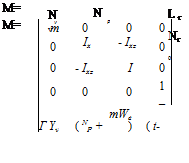
Details of the general equations governing lateral and directional motion are given earlier. It is common practice for lateral/directional motion to assume that all acceleration dependent derivatives are negligible and that the centre of gravity is on the main rotor drive shaft such that dx = dy = dz = 0. Thus:

Mm x = Ma x + Mc u

Control derivatives
Подпись: mg cos 0e 0 0 0

where:

v"

” v"

"YAl

V

p

p

^l

Mc =

L Al

L 0tr

x=

u=

v

r

_0tr _

NAl

N0tr

_Ф_

_Ф_

0

0

To proceed further it is necessary to convert the matrix equation into the form:

x = Ax + Bu

This is achieved by pre-multiplying Mm, Ma and Mc by the inverse of Mm, (M). Noting that r = tjz and including the effect of ^ on lateral acceleration:

1

m

0

0

0

0

0

Izz

Ixz

0

0

(Ixx Iz -12z)

(Ixx Izz -12z)

0

Ixz

Ixx

0

0

(Ixx Izz -12z)

(IxxIzz -12z)

0

0

0

1

0

0

0

0

0

1

M“i =

Hence:

~Yv

(Yp + We)

(Yr – U)

g cos ee

g sin ee

~ya,

Yet~

Lv

LP

L’

0

0

La,

Letr

Iv

NP

I’

0

0

B =

yn,

Ie

etr

0

1

0

0

0

0

0

0

0

1

0

0

0

0

A =

Control derivatives

where:

s — Yv

1

1

Ue — Yr

— g cos ee

g sin e

— Lv

s — Lp

— Lr

0

0

CE =

— Nv

— N

s — Nr

0

0

0

—1

0

s

0

0

0

—1

0

s

Thus for lateral/directional motion, As5 + Bs4 + Cs3 + Ds2 + Es = 0, which usually becomes:

(T s + 1)(T2 s + 1)(s2 + 2^mn s + m2 )s = 0
The four modes of motion are summarized below:

(1) Heading mode. The heading mode is represented by the root s = 0 that indicates that the aircraft has neutral yaw angle stability.

(2) Yawing mode. The yawing mode, which is equivalent to the fixed wing, spiral mode, is represented by (T1s +1) = 0. The mode is independent of roll and lateral translation and is an exponential motion that can be either convergent or divergent. The time constant is moderately long being typically between 5 and 20 seconds.

(3) Rolling mode. The roll mode, described by (T2s + 1) = 0, is a damped subsidence in pure roll. The motion has a short time constant of the order of 1 to 2 seconds.

(4) Lateral/directional oscillation. The Lateral/Directional Oscillation (LDO) or Dutch roll, is an oscillation in roll and yaw, which like the pitching oscillation can be flight condition dependent. Typically the oscillation is unstable in the hover and in a climb.

LATERAL/DIRECTIONAL DYNAMIC STABILITY AND CONTROL RESPONSE

As with the longitudinal axis the lateral/directional dynamic stability of a helicopter is evaluated by observing the longer-term response to a disturbance. The aircraft will be dynamically stable if, following the removal of a disturbance force, it has a tendency to return to the trimmed attitude. Equally control response is again concerned with the response of the helicopter to control inputs made by the pilot. The analysis of the motions is simplified by assuming that there are no cross-coupling effects. Once again the reader should be reminded that this assumption is of questionable validity and care must be taken when reading-across the theoretical results, mentioned below, to the behaviour of an actual aircraft. Before looking at the dynamic modes in detail, it is worth reminding ourselves of the aero-derivatives that influence the lateral/directional motion.

4.11.1 Lateral/directional derivatives

4.11.1.1 Sideslip derivatives

Mechanisms for the generation of sideforce, rolling moment and yawing moment as a result of a lateral velocity disturbance have already been discussed.

4.11.1.2 Roll rate derivatives

(1) Sideforce due to changes in roll rate (Yp). The sideforces produced at the fin, the fuselage and the tail rotor due to changes in the relative airflow direction (and that due to the main rotor flapping) in a roll are generally negligible. This derivative is therefore normally ignored.

(2) Rolling moment due to roll rate (Lp). The main rotor contribution to roll rate damping is analogous to the pitch rate damping (Mq) discussed above. This aerodynamic damping effect is a function of Lock number and the size of the hinge offset. Smaller contributions are also provided by the tail rotor, the fin and the fuselage.

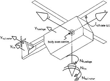
(3) Yawing moment due to roll rate (Np). Contributions to Np depend largely on the size and position of the tail rotor and fin. A high tail rotor, for example, would have a considerable effect, see Fig. 4.20.

4.11.1.3 Yaw rate derivatives

(1) Sideforce due to changes in yaw rate (Yr). It is present but considerable self­cancelling occurs due to effects fore and aft of CG. Yr is therefore usually small enough to be negligible.

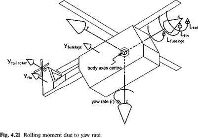
(2) Rolling moment due to yaw rate (Lr). The yaw rate produces a change in the direction of the relative airflow to the fin and tail rotor in particular. The sideforces produce a sizeable rolling moment if their lines of action are sufficiently

image108

Fig. 4.20 Yawing moment due to roll rate.

image109

high above the rolling axis, see Fig. 4.21. If the rotor shaft is at an appreciable angle to the vertical, the main rotor may also provide a contribution to the rolling moment.

(3) Yawing moment due to yaw rate (Nr). If a helicopter yaws to starboard the tail rotor appears to be sideslipping to port. A blade element then experiences relative airflow from a direction that will effectively increase its angle of attack. There will be an associated increase in thrust and this will produce a damping moment opposing the yaw rate. The effect is present in both the hover and
forward flight. A starboard yaw rate also produces relative airflow to both fin and fuselage which gives rise to a net sideforce from each surface. Both associated moments make stabilizing contributions to Nr.

Other contributions to Lv

The contributions to lateral static stability from the tail rotor, the fin and the fuselage all arise as a result of the sideforces produced on these components during a sideslip. The magnitude of each contribution will depend on the individual forces and the distances of their lines of action from the rolling axis. Normally all the contributions are stabilizing. The horizontal stabilizer can also contribute to Lv in a similar fashion to that of the main and tail planes of a fixed wing aircraft. If a helicopter is fitted with symmetrical tail surfaces either side of the tail boom then as the aircraft rolls the downgoing side of the stabilizer encounters the relative airflow at an angle which effectively increases its angle of attack and hence its lift force. The upgoing side will
experience the opposite effect and a decrease in angle of attack and lift. The imbalance provides a moment that acts to stop the roll and, in the subsequent sideslip, any dihedral will further increase this restoring moment.

Lateral (rolling) static stability

Just as the mainplane provides the main contribution to the lateral static stability of a fixed wing aircraft, so the main rotor provides the major contribution in a helicopter. Other contributions come from the tail rotor, fin, fuselage and horizontal stabilizer. Also, as with fixed wing aircraft, no direct restoring moment arises as a result of a disturbance in bank angle (it has zero stiffness about the roll axis). The lateral static stability is, in fact, provided by the sideslipping motion that occurs subsequent to a change in bank angle. Suppose a disturbance in bank angle occurs and is followed by a sideslip to starboard, a rolling moment to port is required to restore equilibrium: Lv must therefore be negative for stability.

Main rotor contribution to Lv

Sideslip induces the characteristic flapback effect with the rotor flapping away from the relative wind direction. This causes a tilt of the thrust vector that will produce a restoring moment about the CG. The magnitude of the rolling moment will be dependent on the size of the flapping angle and the height of the rotor hub above the CG. Offset hinges will also increase its magnitude.