Category Helicopter Test and Evaluation

Flapping motion due to cyclic feathering

The rotor is subjected to a constant feather angle and a feather angle that is varied sinusoidally relative to the hub as expressed by the equation below:

0 = 0o — A1 cos ^ — B1 sin ^ (4.22)

From Equation (4.19) it has already been shown that:

M

P +)2(1 + g)p =_A [4]

If the independent variable is changed from time to blade azimuth angle by means of ^ = )t, then:

Flapping motion due to cyclic feathering

(4.23)


Подпись: M= Flapping motion due to cyclic feathering Подпись: R(1 Подпись: e) r(r + eR) 2 dr

In this scenario lift changes on the blade will arise from two sources: the change in angle of attack caused by the cyclic feathering and the flapping motion itself. It can be shown for an untwisted blade therefore that, since the moment due cyclic feathering is given by:

then the total flapping moment becomes:

Подпись: MA Y -> т7 = 8 )2(1 — e)- iyy 8 (60 — Ay cos ^ — By sin ^)(1 + 2e/3) — (1 — e)(1 + e/3)-jy-

(4.24)

Thus using Equations (4.23) and (4.24): +Y(1—e)3(1+е/3)н^+(1+є)р=8(0O—Ai cos ^—Bi sin ^)(1—e)2(1+2e/3)

(4.25)

Only the steady state solution is of interest here. Thus if the blade flapping is expressed as:

P = a0 — ay cos ^ — by sin ^

Then solving Equation (4.25) gives:

Подпись: [є A — nBy ]Y(1 — e)2(1 + 2e/3 + e2 /3)

8(s2 + n2)

, Y(1 — e)2(1 + 2e/3 + e2 /3) , ni

Ь1 =———————— ^+2)————————————- tnAi + ЄВ1]

Y(1 — e)2(1 + 2e/3 + e2 /3)

a0 = 8(ТТЄ) 0O

n = 8(1 — e)3(1 + e/3)

Now consider the case when the hinge offset is zero. Thus є = e = 0 and:

ay = — By by = Ay a0 = Y©0

Once again confirmation of the existence of a 90° phase shift is given since, for an anticlockwise rotating rotor, rearwards disk tilt is caused by an increase in feather over the starboard quarter and starboard disk tilt is generated by an increase in feather over the nose. Returning to the situation with non-zero hinge offset, examination of

the equations for a1 and b1 indicate that cross-coupling will be present. This can be readily appreciated if the case of an increase in B1 is considered; the magnitudes of both a1 and b1 will be affected. The cross-coupling can be expressed as a phase shift, ф, in terms of the azimuth angle between blade feather and blade flap response. For a blade with a uniform mass distribution:

Подпись: - = (1 - e) g 2Ши

and Iyy = -3 (1 – e)2R2

So from Equation (4.19):

mb Xg eR2 3mb (1 – e)eR2 3e

S = Tyy = 2mb(1 – e)2R2 = 2(1 – e)

Therefore:

Подпись: ф = tan 1y(1 – e)4(1 + e/3)
12e

Figure 4.8 shows the variation of ф with hinge offset and Lock number. The amount of cross-coupling, indicated by the reduction in ф from 90° increases with increasing hinge offset and reduces with increases in Lock number.

It should be noted that Lock number is air density dependent and therefore will reduce with altitude. The cross-coupling caused by hinge offset can be removed by mixing the cyclic feather demand such that when the pilot moves the cyclic stick forward, forward disk tilt is the only result. However, it should be appreciated that the mixing, if mechanically engineered, will only be exactly right at a single density altitude. During a ceiling climb, therefore, significant cross-coupling may occur as

PHASE ANGLE (deg) [ф]

100 80 60 40 20 0
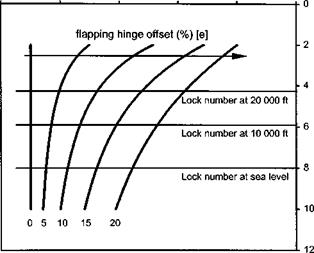
image92

indicated on Fig. 4.8 using a sea level Lock number of 8. As the aircraft climbs the flap response will lead its sea level setting. Consequently, for an anticlockwise rotating rotor more and more roll to starboard will result as a nose down pitch demand is made at higher and higher altitude. This effect is called acceleration cross-coupling since it arises from moments generated by the rotor. Rate cross-coupling arising from a rotor under a steady pitch or roll rate will be covered next.

Disturbed flapping motion at a constant feather angle

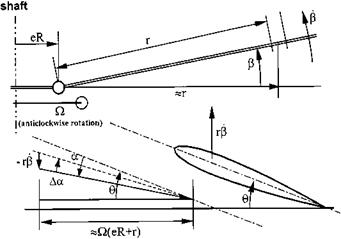
The rotor blades are assumed to be at a constant feather angle and the rotor is taken as rotating steadily at an angular velocity ). Since it is only the disturbed motion that is of interest the aerodynamic moment corresponding to the feather angle will be ignored. When the blade flaps up with angular velocity p, there is a relative down velocity of rp at a point on the blade located r from the hinge, see Fig. 4.7. From Fig. 4.7 it can be seen that for small angles of inflow, flap and flap disturbance:

— rp

Да в tan Да в 4

)(eR + r)

Thus the change in elemental lift, SL, is given by:

1 1 rR 1

SL = 2 pV2c SrCL = —2 p )2(r + eR)2ca r + ^ Sr = —^ p )r(r + eR)pca 8r

image91

Now the aerodynamic moment is obtained by integrating the lift over the blade:

mi – e) mi- e) і

MA = I r dL = — I 2 P 2(r + eR)$ca dr

Jo Jo

= —1 p Qac p R4(1 — e)3(1 + e/3)

8

Therefore:

Подпись: (4.20)Подпись:Mk у . _

T1 =—У )P(1 — e)3(1 + e/3) where:

pacR4

у = —-— = Lock’s inertia number

*yy

Therefore using Equations (4.19) and (4.20) the flapping equation becomes:

p + У )(1 + e)3(1 + e/3)p + )2(1 + g)p = 0 8

Taking Laplace transforms:

^2 + У )(1 — e)3(1 + e/3)s + )2(1 + g) = 0 8

The above second-order equation relates directly to the standard form:

s2 + 2^mn s + m2 = 0

Hence:

Подпись: mn = ) V1 + g and 2у(1 — e)3(1 + e/3)

16V1 + s

The motion described above is damped and harmonic in nature with a natural frequency, mn, of )V1 + s. If the rotor has no flapping hinge offset then both e and s will be zero. Therefore the natural frequency is exactly equal to the shaft frequency and consequently the flap mode is being forced at its resonant frequency; therefore it will display a phase shift of 90° between feather (the input) and flap (the output).

Pure lead/lag motion

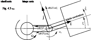
Since a flapping blade is likely to move in the lead/lag sense it is necessary to determine whether the lead/lag motion will cause any rotation about the other two axes. It is now assumed that the flapping angle is zero and the blade moves forward on the drag hinge through an angle E, as in Fig. 4.5. In this case:

Подпись:

Подпись: Fig. 4.4 Pure flap motion.

m1 = 0 m2 = 0 m3 = ) + E

ax = — )2eR cos | ‘і

ay = )2eR sin | I (4.14)

az = 0 J

and making the appropriate substitutions (Equations (4.13) and (4.14) into Equation (4.9):

Подпись: (4.15)L = 0 M = 0

N = Izz | + mbXgeR2 )2 sin | J

Thus when a rotating blade moves solely in a lead/lag sense no moments are generated that cause additional flapping or feathering motion.

4.4.2 Pure feather motion

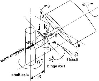
As shall be seen later it is necessary to feather a rotor blade if changes in disk tilt and/ or thrust are desired. Therefore consideration needs to be given to the possibility of feathering motion causing a flap and lead/lag response through mass and inertia effects. The blade is now constrained to feather through an angle 0 whilst the flapping and lagging angles are zero, see Fig. 4.6.

Now from Fig. 4.6:

image88

image89

(4.16)

image90

Fig. 4.6 Pure feather motion.

and:

ax = Q2eR ‘j

ay = О I (4.17)

az = О J

As before, substituting Equations (4.16) and (4.17) into Equation (4.9):

L = Ixx 0 + Ixx )2 sin 0 cos 0 M = Iyy )0 cos 0 — Iyy )0 cos 0 N =— (Ixx + Iyy) )0 sin 0 — (Ixx — Iyy) )0 sin 0 Hence:

L = Ixx0 + Ixx)20 "J

M = О і (4.18)

N =—2Ixx )0 0 J

The lagging moment due to feathering, 2Ixx)00, is usually extremely small when compared with the Coriolis flapping moment and can be neglected.

4.2 FLAP DYNAMICS

The above analysis and Equations (4.12), (4.15) and (4.18) show, to a first approxi­mation, that the only dynamic linkage between flap, lead/lag and feather is the Coriolis effect that causes a flapping blade to lead or lag. Thus in the absence of a S3 hinge,

lead/lag motion will not feedback to affect the flap response and it can be assumed that the feathering motion required to produce a flap response aerodynamically will not generate any dynamic effects that modify the flap behaviour. Consequently for the rotor the most fundamental dynamic equation is the flapping equation:

M.

Iyy p + )2(Iyy + mb Xg eR2 )p =-M or p + )2(1 + є)Р = Iа (4.19)

Iyy

To determine the nature of the flap dynamics it is necessary to consider the nature of the aerodynamic forcing. Three scenarios will be used to expose the basic dynamic characteristics of a typical rotor: a flap disturbance, the application of cyclic feathering and the application of a steady pitch/roll rate to the rotor. For simplicity all assume the helicopter is initially in a trimmed OGE hover.

EQUATIONS OF FLAPPING MOTION

Development of the equations of flapping motion begins by considering a rotor system with a single hinge mounted a distance eR from the axis of rotation. The shaft rotates with a constant angular velocity, ), and the blade flaps with angular velocity, |3. If axes are fixed in the blade (see Fig. 4.3) then the dynamic situation can be described using [4.1]:

L = Ixx m і + Ixx m2 m3 I

M = Iyym2 – Iyym3 m1 – mbXgRaz V (4.9)

N = (Ixx + Iyy)m3 – (Ixx – Iyy)m1 m2 + mbXgRay J

image86

Fig. 4.3 Rotor axes system.

The axes are set to be parallel to the principal axes with their origin at the hinge, such that the i-axis lies along the blade span, the j-axis is perpendicular to the span and the k-axis completes the right-hand set. Although the blades are in reality highly flexible, it will be assumed, for simplicity, that they are rigid. If Ixx is the moment of inertia about i and Iyy is the moment of inertia about j then Izz, the moment about k, is given by Izz = Ixx + Iyy. Note that m1, m2 and m3 are the angular rates about the principal axes and ax, ay and az represent the acceleration of the hinge.

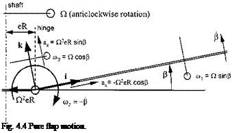
4.4.1 Pure flap motion

Analysis begins by assuming that the blade is constrained so that only flap motion is possible, see Fig. 4.4. From Fig. 4.4 it can be seen that the angular components of velocity, m1, m2 and m3 are given by:

m1 =) sin p ‘j

m2 = -p і (4.10)

m3 = )cos p J

Also the absolute acceleration of the axis system, a0, is given by:

a0 = ax i + ay j + az k

a0 = – Q.2eR cos pi + )2eR sin p k

Hence:

ax = — Q2eR cos P ‘j

ay = 0 і (4.11)

az = )2eR sin P J

Now substituting Equations (4.10) and (4.11) into Equation (4.9) and assuming small P:

L = 0

— M = 1yyP + )2(iyy + mbXgeR)P > (4.12)

— N = 2 )1yy psin P J

In other words if a rotating blade flaps upwards then in order to maintain it within the flapping plane no feathering moment is required but a rearwards moment of 2)1yypsin p is necessary. This moment is equal and opposite to the Coriolis moment acting on the blade; it is usually so large that it is often relieved by a drag hinge. Therefore if the blade is hinged so that it is able to move in an in-plane sense then as the blade flaps up it will move forward or lead.

EQUATIONS OF MOTION FOR A RIGID AIRFRAME

To fully understand the stability characteristics of an aircraft and why certain responses occur, it is necessary to determine the equations governing its motion and to define the parameters that dominate and influence them. The method used in this chapter to develop the necessary equations relies on a number of simplifying assumptions but applies to any rigid body (neglecting any structural distortion) which is subjected to small disturbances. By making such assumptions these essentially non-linear equations can be linearized and the task of analysing them is made much simpler.

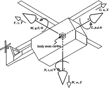
Figure 4.2 shows a set of rectangular axes (O, x, y, z) fixed in the helicopter (body axes) with its origin at the body axes centre. Note that at this level of complexity the rotor dynamics are ignored. The rotor is assumed to be a fixed force and moment generating device. The components of velocity and force along the Ox, Oy and Oz axes are U, V, W and X, Y, Z respectively. The components of the rates of rotation about the same axes are p, q and r and the moments L, M and N. After Babister [4.2], consider an arbitrary point P at position x, y, z from the body axis centre, which has local components of velocity and acceleration u, v, w and ax, ay, az respectively.

The absolute velocity of the point P is now obtained by superimposing the velocity of the body axes centre onto the relative velocity of the point P. P is moving relative to the body axes centre, but this centre is also moving, so the absolute velocity of P is given by the sum of these two components. The body axes centre is moving with velocity U, V, W so denoting the absolute velocity of P by u’, v’, W leads to:

image84

Fig. 4.2 Body axes system.

and similarly, the absolute accelerations are:

a’x = u’ — rV + qw’ dy = V — pW + ru! dz = W — qu’ + pv’ (4.2)

The values of u’, v’, W’ can be obtained by differentiation and since the airframe is rigid, y = x = z = 0:

u’ = І7 — yv + zq v’ = V — zp + xv w’ = W — xq + yp Substituting for u’, V, W and for u’, V, W’, using Equations (4.1) and (4.2), leads to: dx = U — rV + qW — x(q2 + r 2) + y(pq — V) + z(pr + q) 4

dy = rU — V—pW + x(pq + V) — y(p2 + r 2) + z(qr — p) > (4.3)

az =—qU + pV + W + x(pr — q) + y(qr + p) — z(p2 + q2) J

Having obtained expressions for the components of the absolute acceleration of the point P, consideration must now be given to the forces acting on the helicopter. To this end, consider an element of mass Sm at the point P Using the formula F = ma, the forces producing the components of acceleration a’x, dy, dz are dx Sm, dy Sm, dz Sm respectively. The total force is obtained by summing the components of force at all such points over the whole helicopter using Equation (4.3):

X = m{U — rV + qW — dx (q2 + r 2) + dy (pq — V) + dz (pr + q)} 4

Y = m{rU +V—pW + dx (pq + V) — dy (p2 + r 2) + dz (qr — p)} > (4.4)

Z = m{ — qU+pV + W + dx(pr — q) + dy(qr + p) — dz(p2 + q2)} J

where dx, dy, dz are co-ordinates of the centre of gravity from the body axes centre. The forces acting on the particle at point P will each have an associated moment

about the axes. First consider the moments about the Ox axis; these will be rolling moments and will be denoted by L.

The elemental force Sm. a’z has a moment about Ox given by:

moment = (Sm. a’z )y clockwise

The elemental force Sm. a’y has a moment about Ox given by:

moment = (Sm. a’y )z anticlockwise

Since the third elemental force Sm. a’x has no moment about Ox, the total moment for such points is given by:

L = & Sm(a’z y — a’y z)

Hence from Equation (4.2):

l=p&(zi)8m+<f2—Sm+^—q&xym (4.5)

— (pq + r)&xzSm + ( — qU+pV+ W)&ySm — (rU+ V—pW)&zSm )

Moments and products of inertia are defined about the body axes centre as follows:

[Ixx ]b = &( y2 + z 2 )Sm = moment of inertia about x axis [Iyy ]b = &(x 2 + z 2)Sm = moment of inertia about y axis [Izz]b = &(x2 + y2)Sm = moment of inertia about z axis [Iyz ]b = & yz Sm = product of inertia about y and z axes [Ixz ]b = & xz Sm = product of inertia about x and z axes [Ixy ]b = & xy Sm = product of inertia about x and y axes

So equation (4.5) can be rewritten as:

image85L = p [Ixx ]b + qr([izz ]b — [Iyy ]b) + (r 2 — q2 )[iyz ]b + (pr — q)[lxy ]b
— (pq + r)[Ixz ]b + ( — qU+pV + W) &y Sm — (rU + V—pW) &z Sm

Since the body axes centre is not necessarily at the centre of gravity the following transformation is required:

[Ixx ]b = Ixx + m(d 2 + d|)

[Iyy ]b = Iyy + m(d 2 + d 2)

[Izz ]b = Izz + m(d 2 + d 2)

[Ixy ]b = Ixy + mdx dy [Ixz ]b = Ixz + mdx dz [Iyz ]b = Iyz + mdy dz

Therefore Equation (4.6) becomes:

L = pIxx + qr{izz — Iyy} + (r 2 — q2 )Iyz + (pr — q)Ixy — (pr + r)Ixz — Ydz + Щ

By a similar analysis, equations for moments M and N can be determined:

L = ptxx + qr{Izz – Iyy} – (pq + f)Lcz – (q2 – r 2 )Iyz – (q – pr)Ixy – Ydz + Zdy Ї M = qIyy-pr{Ixx – Izz} – (r 2 p2 )Ixz – (r – pq)Iyz – (p + qr)Ixy – Zdx + Xdz (4.7)

N = rIzz + qp{Iyy – Ixx} – (p – qr)Ixz – (q +pr)Iyz – (p2 – q2)Ixy – Xdy + YdxJ where dx, dy, dz are co-ordinates of the centre of gravity from the body axes centre and Ixx, Iyy, Izz, Ixy, Iyz, Ixz are the moments and products of inertia about axes through the centre of gravity parallel to Ox, Oy, Oz. Linearizing the force and moment equations (Equations (4.4) and (4.7)) by means of the small perturbation theory and assuming that the CG is co-incident with the body axes centre leads to:

X = m{u + qWe}

Y = m{v – pWe + rUe}

Подпись: (4.8)Z = m{w – qUe}

L = Ixx p – Ixz r M = Iyy q

N = Izz r – Ixz p J

Noting that the forces and moments arise from aerodynamic, gravitational and control sources and introducing the concept of derivatives, Equation (4.8) becomes:

mu = uXu + wXw + q(Xq – mWe) – Qmgcos0e + B1 XBi + 0cX0c

mr = vYv + p(Yp + mWe) + r(Yr – mUe)

+ фmg sin 0e + tymg cos 0e + A1 YAl + 0TR Y, TR

mw = uZu + wZw + q(Zq + mUe) – 0mgsin0e + BAZB| + 0cZ0c

Ixx p – Ixz r = vLv +pLp + rLr + a1 La + 0TR L0TR

Iyy q = uMu + wMw + qMq + Bi MB| + 0c M0c Izzr – Ixzp = v^Vv +pNP + rNr + A! NAl + 0TRT^0TR

These equations are often expressed in matrix form as indicted below in the discussions on dynamic stability and control response (Section 4.11).

Normalized and non-dimensional derivatives

Although the full set of derivatives introduced above may be needed for an accurate mathematical representation of rotorcraft dynamic characteristics they are not all required when discussing typical helicopter handling qualities. Since the pilot is most interested in the attitude changes that occur as a result of control input and atmospheric disturbances mainly moment derivatives will be retained in the reduced set. Due to their widespread use, most of these derivatives have acquired a common descriptor based on their effect on the stability and control characteristics of a typical helicopter, see Table 4.4.

All the derivatives considered so far are affected by the aerodynamic characteristics of the aircraft. They will therefore be modified by changes in flight condition (density altitude, airspeed, rotor speed) and rotorcraft design (rotor radius, blade area). In order to make appropriate comparison it is common practice to make aero-derivatives non-dimensional in a similar manner to that used for lift and drag. In addition, as shall be seen later, when the equations of motion governing aircraft behaviour are manipulated it is sometimes convenient to normalize the derivatives using the mass and inertia properties of the helicopter. There is unfortunately no internationally agreed set of standard symbols used to distinguish between these various classes of aero-derivatives. A set appropriate to rotorcraft that has been developed from those used by Babister [4.2] is presented in Table 4.5.

Aero-derivatives help us understand the stability and control characteristics of

Table 4.4 Most commonly used aero-derivatives.

Common descriptor

Common descriptor

Xu

Drag damping

L

Roll damping

Yv

Side force

Mq

Pitch damping

Zw

Heave damping

Nr

Yaw damping

Lv

Lateral static stability

LA

Roll control power

Mu

Speed stability

MB

Pitch control power

Mw

Angle of attack stability

NeTR

Yaw control power

Nv

Directional static stability

Ze0

Heave control power

Tail rotor roll

Ye

eTR

Tail rotor drift

Mec

Pitch change with power

Nec

Torque reaction

Table 4.5 Symbol set for various classes of aero-derivative.

Non­Dimensional Normalized dimensional

Derivative type

derivatives

Divisors

derivatives

Divisors

derivatives

Force/linear velocity

Xu Y Zw

mass

Xu Yv Zw

psAQR

xu yv zw

Force/angular velocity

Xp Y Zr

mass

Xp Yq Zr

psAQR2

xP yq z

Moment/linear velocity

Lu Mv Nw

inertia

Lu Mv Nw

psAQR2

lu mv nw

Moment/angular velocity

LP Mq Nr

inertia

Lp Mq Nr

psAQR3

lp mq n.

Force/control deflection

XAl YBl Z0c

mass

XAl YB Z0c

psAQ2R2

xA yBl z0c

Moment/control deflection

L A MB N%

inertia

LA mb n%

psAQ2R3

lA mB n0c

rotorcraft by providing a convenient manner through which to describe the factors that affect these characteristics. Equations of motion can be developed that tie these derivatives directly to the dynamic behaviour of rotorcraft. It is possible, therefore, to determine the particular derivatives that are key to shaping the pilot’s perception of his aircraft. Likewise, the contribution made by the components of a typical helicopter to these derivatives can be identified and how the design choices made by rotorcraft manufacturers may affect the suitability of a helicopter for a particular role can be understood. Aero-derivatives are, therefore, fundamental to any study of aircraft stability and control.

Derivation of aerodynamic derivatives

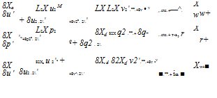
So far, the discussion has been restricted to force changes caused by modifications to the angle of attack. Also small changes (smallperturbations) and linear rates of change have been assumed. A completely general approach would be to include other variables and to allow for non-linear changes. A series of Taylor expansions provide us with a convenient method of expressing these more complex relationships. Therefore, with reference to the body axes [4.2]:

Подпись: 8Xa 8u ' L2X u2 M + 8u2 .2!.' LX L2X v2 '.etc.+8v • V +8v2a. 2!.' X ,.etc.+—^. w w+ 8X 8p ' L2X p2 'w+8p2a. 2!.' 8Xd 82X q2 .etc.+ 8q- q+ 8q2 . 2!. X ..etc.+ т-a, r r+ 8X 8u ' 82Xa u 2 'u + 8u2 .2!.' 8X,d 82Xd v2 '.etc.+8v •V +8v^.2!.' X ■.etc.+ isa ■ w+■ Подпись: Xa = Xae +Подпись: +Подпись: +Подпись: d2X w2 HX. 2! ...etc. Подпись: 82X r2Подпись: Sr2 '2! 82Xa w2 8w2 . 2!.

image83

. —… etc.

LX 82X P2 LX 82X f LX L2X r2

+X •p +~LpX. гт^+І^ •q+~dX. i…etc.+17 •r +17. 27^

+ higher-order terms

where

Xa = aerodynamic X-force

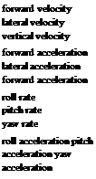
Xae = equilibrium X-force generated when the aircraft is in trim u = change in longitudinal speed from trim v = change in lateral speed from trim

w = change in vertical speed from trim p = change in roll rate from trim q = change in pitch rate from trim r = change in yaw rate from trim

u = longitudinal acceleration v = lateral acceleration

w = normal acceleration p = roll acceleration q = pitch acceleration r = yaw acceleration.

-ТГ -r. л л л л л л

Xa = Xae + 17 • U +17 • V + 17 • W +1P" •P +17 • q +ИІ ■ Г

Derivation of aerodynamic derivatives

If the small perturbation assumption is retained it is again possible to linearize factors in this more complex relationship. Thus if second and subsequent terms in each Taylor series are assumed to be negligible then:

Подпись: LX LX a у a. = Lu v= Lv Подпись: LX Xw = 17-etc-

Now applying standard aero-derivative notation:

Which leads to:

Xa — Xae + Xu. u + Xv. v + Xw. w + Xp. p + Xq. q + X. r + Xu. u + Xv-. v

+ Xw. w + Xp. p + Xq. q + X. r

And applying the same analysis to the other forces and moments acting on a helicopter yields the following set of aero-derivatives:

Xu

Xv

Xw

Xp

Xq

Xr

Xu

Xv

Xw

Xp

Xq

X

Yu

Yv

Yw

Yp

Yq

Y

Yu

Yv

Yw

Yp

Yq

Y

Zu

Zv

Zw

Zp

Zq

Zr

Zu

Zv

Zw

Zp

Zq

Zr

Lu

Lv

Lw

Lp

Lq

Lr

Lu

Lv

Lw

Lp

Lq

Lr

Mu

Mv

Mw

Mp

Mq

Mr

Mu

Mv

Mw

Mp

Mq

M

Nu

Nv

Nw

Np

Nq

N

Nu

Nv

Nw

Np

Nq

N

Подпись:

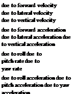
Подпись: forward velocity lateral velocity vertical velocity forward acceleration lateral acceleration forward acceleration roll rate pitch rate yaw rate roll acceleration pitch acceleration yaw acceleration

Table 4.1 Force derivatives.

Подпись:Derivation of aerodynamic derivatives
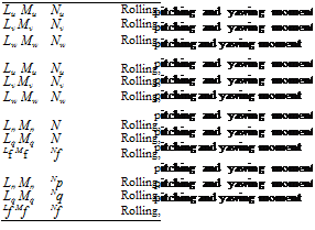
Table 4.2 Moment derivatives.

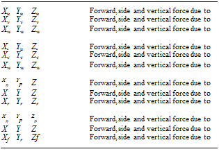
Using the body axes system it is possible to give a precise meaning to each of the aero-derivatives introduced above, see Tables 4.1 and 4.2.

When the pilot moves a control in the cockpit he will cause changes to the pitch of the appropriate rotor blades. These control inputs will in turn generate off-trim forces and moments in a manner analogous to the effect of gusts. It is possible therefore to identify a set of control derivatives based on the following control deflections from trim, see Table 4.3:

A1 or 01s = lateral cyclic pitch

B1 or 01c = longitudinal cyclic pitch

0c = collective pitch

0TR = tail rotor collective pitch

Derivation of aerodynamic derivatives

Forward, side and vertical force due to lateral cyclic pitch Forward, side and vertical force due to longitudinal cyclic pitch Forward, side and vertical force due to collective pitch Forward, side and vertical force due to tail rotor pitch

Подпись:Подпись: IKRolling, pitching and yawing moment due to lateral cyclic pitch Rolling, pitching and yawing moment due to longitudinal cyclic pitch Rolling, pitching and yawing moment due to collective pitch Rolling, pitching and yawing moment due to tail rotor pitch

AERO-DERIVATIVES FOR ROTORCRAFT

During the different phases of a helicopter’s flight it is subject to a number of forces and moments that must be balanced if the aircraft is to remain in trim. Alternatively should the pilot wish to control the helicopter by modifying its flight path he must generate an out-of-balance condition by moving the flight controls from their trim position. On the other hand atmospheric disturbances may upset the force and moment balance and cause the flight path to change unintentionally. The nature of the out-of­balance condition following such a gust affects the stability characteristics of the rotorcraft by dictating whether the helicopter will return to trim without pilot intervention. The amount by which flight controls and atmospheric disturbances modify the forces and moments acting on a rotorcraft are the key to determining its stability and control characteristics. Typically, these forces and moments can be changed by any of the following, alone or in combination:

(1) Disturbances in linear speeds or angular rates;

(2) Changes in main rotor and tail rotor blade pitch;

(3) Movement of the centre of gravity position.

Measuring or predicting how a given force or moment will change as a result of variations in the above parameters is fundamental to determining the handling qualities of a particular air vehicle. A shorthand based on the derivative has therefore been developed to simplify discussion of these effects.

4.2.1 The derivative

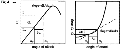
The concept of the derivative is best understood by means of a simple example. Consider an aircraft in trimmed straight and level flight at an angle of attack (AOA) a0. If the variation of the lift and drag can be simply portrayed, as in Fig. 4.1, it is possible to determine their trimmed values (L0 and D0).

Suppose as a consequence of a gust the AOA is increased by da to a1. From Fig. 4.1 it is a simple matter to determine L1 and D1. If, however, only small changes in AOA occurred it would be possible to calculate changes in lift and drag using the local slope around the trim point. Thus:

L – L = dL = dL da and D – D = dD = dDda da da

Since these slopes represent the rate of change of lift and drag with AOA around the trim point, they can be used directly to calculate the change in these forces. As shall be seen later, all equations of motion assume the aircraft is in equilibrium prior to being disturbed by a gust or pilot action. Thus in our example, a, L and D should represent the change in AOA, lift and drag from their equilibrium values. Therefore, written more formally:

r dL dD

L = —— a and D = —— a da da

Alternatively, taking note of the symbols used for vertical and horizontal forces and standard aero-derivative notation:

L = — Z = La. a= —Za. a and D = — X = Da. a= — Xa. a

In fact, modifications to the AOA can result from changes in forward speed (u) and from changes in vertical speed (w). Thus more generally:

X = Xu. u + Xw. w and Z = Zu. u + Zw. w

Stability and Control Theory

4.1 INTRODUCTION

The detailed study of helicopter stability and control is a complex matter that is beyond the scope of this book. Therefore, a simpler approach will be taken making use of several common assumptions: the rotor speed remains constant; in disturbed flight the rotor behaves as if the motion were a sequence of steady conditions; and the lateral/directional and longitudinal motions are decoupled. The rotor is, therefore, regarded as responding instantaneously to speed and angular rate changes. Stability and control theory aims primarily at finding the factors involved in designing an aircraft with satisfactory flying qualities and in order to make an accurate assessment of an aircraft’s handling qualities it is important that these factors are understood. The main rotor provides the largest contribution to the total stability and the way in which it flaps is most important. Consideration of rotor flapping in the hover and forward flight, before an investigation of helicopter stability, will be instructive.

Practical helicopter and autogyro flight was not possible until rotor hinges were fitted to relieve the large bending stresses and rolling moments that arise in forward flight. The most important of these hinges is the flapping hinge that allows the blade to flap, that is to move out of the plane of rotation. However a blade that is free to flap experiences large Coriolis moments [4.1] in the plane of rotation and therefore a further hinge called the drag or lag hinge is required to relieve these moments. Finally, another hinge, the feathering hinge, is provided to allow adjustment of the blade pitch, or feathering, angle. A rotor incorporating these hinges is referred to as fully articulated. The sequence of hinges is not always the same. The flapping hinge is usually the most inboard hinge but some helicopters have intersecting flapping and drag hinges and some have the drag hinge outboard of the feathering hinge. Also, as described below, hinge axes are not always mutually perpendicular.

It is advantageous to provide aerodynamic damping to the flapping motion of a rotor blade. A blade that is free to flap will move such that the combination of the lift, blade weight and centrifugal force are in equilibrium. However a further spring effect can arise if reduced lift occurs with increased flap. Such a positive pitch-flap coupling can be engineered by arranging for the blade pitch to be reduced with increased flap angle by means of a skew of the flap hinge line so that it is no longer perpendicular to the radial axis of the blade. The angle of skew is referred to by the symbol S3, hence the name the delta three hinge. The blades of a two-bladed rotor are usually mounted as a single unit on a teetering hinge. There are no drag hinges as underslinging the rotor greatly reduces the lagging moments generated by the Coriolis effect. When the underslung rotor flaps the radial velocities of points above the hinge line are negative whereas those below are positive. The corresponding Coriolis forces are of opposite sign and if the hinge height is chosen carefully the moment at the blade root can be reduced to a second-order effect. Preconing also helps in this respect.

Several problems are associated with articulated rotor heads. The bearings of the hinges and dampers operate under very high centrifugal loads, requiring frequent servicing and maintenance. When the number of blades is large the hub can become extremely complex and bulky, especially if automatic blade folding is incorporated; thereby contributing a large proportion to the total drag of the helicopter. Improve­ments in blade design and construction have led to the development of the hingeless rotor. The flapping and lagging hinges have been dispensed with, the motion in these two senses being allowed by flexible elements within the hub and blade root.

DETERMINATION OF PERFORMANCE LIMITED PARAMETERS

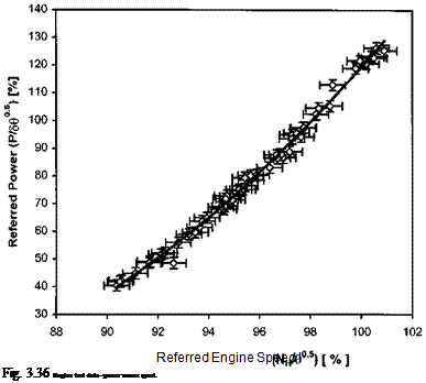
Quite often one of the objectives of a flight test programme is to determine the parameter that will limit the performance under the atmospheric conditions likely to be experienced in the role. Under certain atmospheric conditions, usually hot and high, the engines, rather than the transmission will limit the performance. It is therefore necessary to determine the precise limiting factor for the conditions specified. The method is relatively simple but requires access to engine performance data such as that shown in Figs 3.36 and 3.37. The analysis proceeds by obtaining the actual limiting values from the aircraft documentation; these values will be called QLIMIT, rLIMIT and NLJM1T. Using the pressure altitude and air temperature specified the transmission limited referred power (TLRP) = QLIMIT m/8^9 is calculated. The engine temperature limited referred power (ETLRP) is obtained using Fig. 3.21 and the

DETERMINATION OF PERFORMANCE LIMITED PARAMETERS

image79

Fig. 3.37 Engine test data – power versus temperature.


Referred Engine Temperature (Te/0) [ °С ]

image80

Fig. 3.38 Limiting performance – level flight speed.

image81

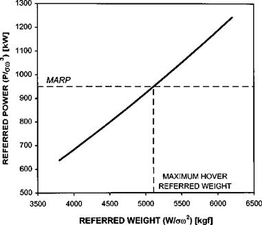
Fig. 3.39 Limiting performance – hover mass.

image82

appropriate value of TLIMIT/0. Likewise the engine speed limited referred power (ESLRP) is found using Fig. 3.22 and the appropriate value of NLIMIT^0. If either ETLRP or ESLRP is less than TLRP then the performance will be engine-limited under the conditions specified.

Подпись: MARP =
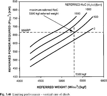
Подпись: PMAX Подпись: LRPMIN (m/V0)3

It is now possible to determine the maximum performance available by choosing the lowest limited referred power, now called LRPMIN, and for a given rotor speed calculating the maximum available referred power (MARP) from:

This value can then be used to determine a variety of performance limited parameters, such as: the maximum level flight speed, VH, (see Fig. 3.38), maximum hover mass (Fig. 3.39) or maximum vertical rate of climb at a given hover mass (Fig. 3.40).

Chapter 4