Category Helicopter Test and Evaluation

Test conduct

Systems testing can be divided conveniently into three main areas of interest: the interface with the operator, performance, and system integration. The interface with the operator breaks down in turn into the areas of information and control. Informa­tion covers the data input that the system needs from the operator, evaluating the ease with which it can be provided, and also covers the information provided by the system to the operator. In the later case it will be necessary to answer such questions as:

• Is the information presented in the required format?

• How easy is it to assimilate?

• What workload is required to monitor system performance?

• Are failures indicated adequately?

Assessing control aspects involves examining the range, degree and ease of control provided. In essence it answers the question ‘Can the operator make the system perform the required function within its capabilities and can this be achieved easily?’ It should be remembered that there may be limits to the amount of control that an operator should be given. For example it would not be desirable to allow a pilot the option of completely disabling visual or audio warnings. Another example would be providing individual lighting controls for each cockpit instrument, this would give the pilot complete control but it would be difficult and time consuming to exercise it.

Clearly evaluating the adequacy of control and the operator interface are largely a subjective process, while evaluating performance can often be an objective process. The system performance can be broken down into quantitative and qualitative performance. In the case of a navigation system the quantitative performance or accuracy is determined by comparing actual position measured from accurate maps or pre-surveyed points with displayed position. For a weapon system the accuracy of firing tests is measured against required accuracy. With other systems, such as displays and piloting vision aids, assessing performance relies to a large extent on the qualitative opinion of the pilot or operator. When dealing with qualitative aspects of systems testing it is important to describe fully the way that the performance impacts on the conduct of role tasks. As in all testing the fundamental question is ‘Does the system contribute sufficiently to the efficient conduct of the mission?’

The last area to be discussed is systems integration. In the past most aircraft systems were stand-alone and the pilot was required to monitor the status and output of all the systems individually: the only integration which took place was in the pilot’s head! This led to a high level of pilot workload. As more and more systems have been added to rotorcraft and operational tasks have become more demanding the need to off-load the crew has become increasingly important. The systems on board should share information so that the pilot or operator is not required to enter information more than once, pass information from one system to another or make unnecessary control selections. Examples of good integration might include automatic display of a cable hover screen when the sonar is armed or display of a pre-landing checklist as the final point on the navigation plan is approached. When assessing the adequacy of integration within an aircraft realistic simulated missions are conducted and the actions required of each crew member analyzed with regard to the systems. If any of the actions could be eliminated or made easier then the integration is deficient.

Preparation for systems testing

The first, and most important, stage of systems testing is to determine the exact operational requirements. In other words what precisely is needed from the system to allow the pilot or operator to achieve the task or mission. The word precisely is important here because it is not just a question of defining the function that the system must meet but also defining the degree of accuracy required. Taking the example of a navigation system, the test team needs to understand what information the pilot will need (heading to steer, time to go, ETA, track error), at what point in the mission each item of information will be required, what the crew need to do with the information, and to what degree of accuracy the navigational information will be required. Staying with the last point, it is clear that if the navigation system feeds into an on-board weapon system a higher degree of accuracy will be required than if the information is only required for steering information by the crew. Similarly the accuracy needed in an air data system will also need to be higher if it has an input into the firing solution of a gun system.

Once the operational need is clearly understood a thorough understanding of the system under evaluation is needed. Part of the process is for the test operator to

become proficient in its use. Becoming fully ‘worked-up’ can prove difficult with new systems as the training material and system documentation are sometimes not available. However, allowing sufficient time to achieve proficiency is included in the test planning. The effect of partial and total system failure is also addressed during the preparatory stage by conducting a failure modes, effects and criticality analysis (FMECA).

Armed with an understanding of the operational requirements and knowledge of the system itself the test planning takes place. As with all testing the aim is to evaluate the system as comprehensively as possible under operationally realistic conditions. The facilities required to conduct the programme will vary according to the system but this type of testing can often require complex instrumentation and significant external resources such as ranges, airspace and radar targets.

Systems Testing

7.1 METHODOLOGY

All helicopters, whatever their role, incorporate a number of systems to enable the aircraft to fly. Even the simplest of helicopters have flight controls and powerplant systems. With modern military rotorcraft it is not an exaggeration to say that the aircraft is merely a means of taking the various systems to the required location. The recent policy of awarding prime contractor status to system integrators rather than helicopter manufacturers illustrates this last point.

The systems onboard a rotorcraft can be divided into two major categories. The first category contains those systems that are required to allow the helicopter to fly but which do not require significant interaction with the crew other than monitoring. Examples of this category include engine lubrication, hydraulics, and electrical systems. Testing of these types of systems is beyond the scope of this book. The second category comprises systems that do require significant interaction with the crew to enable the aircraft to accomplish the mission. Examples of major types of system from this category include:

• flight controls,

• stability augmentation,

• cockpit displays and controls,

• air data,

• powerplant(s),

• navigation,

• weapons,

• sensors.

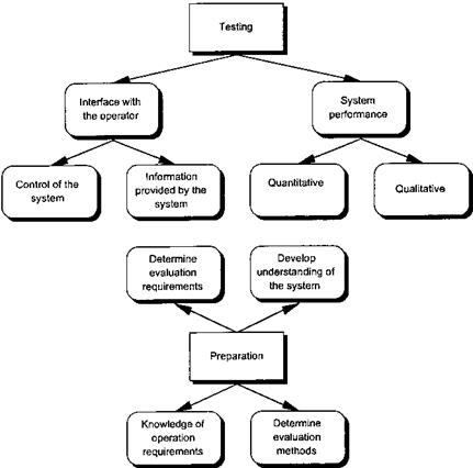
The first system on the list, flight controls will not be covered further in this chapter as the test techniques have already been described. The last three systems are examples of systems that are not required for flight but are needed if the mission is to be conducted safely and successfully. The principles involved in testing these mission systems are covered here but a detailed examination is again beyond the scope of this book. Although the function, design and operation of aircraft systems may vary widely it is possible to define some common principles to employ when evaluating any system. It is convenient to divide these into preparation activities and test activities Figure 7.1 shows the principles.

image180

Fig. 7.1 Systems testing methodology.

Mission modes

Mission modes are included in autopilots intended for specific roles. As such they are not usually included in AFCS fitted to civilian helicopters unless they are expected to have a SAR capability as well as being suitable for single pilot IFR.

Auto-transition mode. Helicopters intended for ASW or SAR operations will usually have an autotransition mode provided by the autopilot. From a start point at a radio altitude of about 200 ft and airspeed close to that for minimum power, the AFCS will execute a programmed manoeuvre using both the pitch and the collective channel. Thus under that action of the autopilot the helicopter will decelerate and descend to hover at pre-selected radio altitude. It is usual to arrange that appropriate movements of the longitudinal cyclic or collective inceptor by the pilot will cause the programming of either altitude or airspeed to cease thereby enabling him to fly a modified profile or abort the manoeuvre. At the end of the program the helicopter will usually enter a hover with plan position held using signals from the Doppler and/or inertial/GPS system. Radio altitude will be maintained using the basic altitude hold mode. Certain autopilots have an additional mode that programs the helicopter from higher altitudes, up to 2000 ft, and higher speeds to a flight condition from which the basic autotransi­tion mode can be engaged.

Hover position hold. Hover position hold is achieved through the pitch and roll channels. The sensors used to generate the error signals will depend on the type of hover required. Plan position can be maintained accurately using a combination of signals from longitudinal and lateral accelerometers (translational acceleration), Doppler receivers (translational rate) and GPS (present position and translational rate). Hover position relative to a dipping sonar is often maintained using cable angle sensors. In some helicopters a rudimentary hover hold capability is provided using the basic attitude hold mode.

Translational rate command. Translational rate command (TRC), in the form of an auxiliary hover trim (AHT), has been available for a number of years on certain AFCS designed for SAR operations. Deflections of the inceptor, located at a crewman’s station, commands a rate of horizontal translation. Centralizing the inceptor will cause the system to maintain the selected rate as sensed by the Doppler radio receiver. Full deflection usually commands a fairly modest rate, typically 10 kts, in keeping with the hover trimming function of this mode.

Automatic circuit. A relatively new autopilot feature, again provided for SAR opera­tions, is the automatic circuit or Mark on Target (MOT) mode. The pilot overflies a desired point on the surface, usually the location of a survivor, and engages the mode. The existing flight path control functions of the AFCS then turn the helicopter downwind and initiate a deceleration and descent to the autotransition gate conditions. Some time later, using Doppler information, the helicopter turns into wind and at the appropriate point the autotransition mode is engaged and the aircraft descends and slows to a hover at an altitude pre-selected by the pilot. The navigation system will usually arrange for the hover to be established a short distance from the MOT point so that the AHT mode can be used for final plan positioning.

Dip-to-dip. Another relatively new AFCS mode is the so-called ‘dip-to-dip’ function. This uses a combination of hover-position hold, automatic transition and Doppler/ IN/GPS based navigation to move the sonar equipped helicopter from one dipping location to another. The aim of this mode is to move the helicopter in the shortest possible time commensurate with the available performance and the ambient wind conditions.

Chapter 7

Navigation modes

Now that the helicopter is capable of airspeed, altitude, heading and vertical speed control it is possible to use these modes in combination to provide automatic navigation and approach to a landing site. Navigation modes include heading selection, VOR, ILS, Back Course, Go-around and On-route Navigation.

Heading selection. The heading selection (HDG) mode differs from heading hold in that large heading changes may be required and, therefore, the mode is achieved through the roll channel. As mentioned above, heading selection may be a mode performed by the autopilot separate from the ASE heading hold function. Alternatively both modes can be performed by the autopilot. The heading error signal may be scheduled as a function of TAS in order to ensure the helicopter executes ‘Rate 1’ turns. In addition a bank angle limit may be included to prevent excessive roll attitude changes at high speed.

VOR tracking. VOR tracking is a mode common to most autopilots and is designed to provide automatic intercept, capture and tracking of a selected VOR radial. Typically the pilot will tune the navigation receiver to the desired VOR frequency, select a VOR radial and using the HDG mode set a heading that will intercept the desired course. As the helicopter approaches the beacon the VOR signal is monitored for beam deviation, beam rate and validity. At the appropriate time the helicopter is steered towards the beacon and eventually the radial will be captured, with the helicopter flying in the desired direction. Steerage on to the radial is usually achieved in stages either by using a 45° ‘cut’ or successive cuts of up to 30°.

This feature is designed to avoid overshooting the beam when large intercepts are used at high speeds. Some autopilots automatically reduce the bank angle and roll rate limits to avoid over-controlling as the beam centre is approached. On entering the cone of confusion located overhead the beacon an Over Station Sensor (OSS) warning will be given to the pilot. The link between the radio receiver and the autopilot is severed and the system will usually revert to heading hold. Once the signal becomes usable again the link is restored and radial tracking is resumed. Some systems will increase the bank angle and roll rate limits on re-engagement to ensure rapid re­acquirement of the beam centreline in gusty conditions. If the pilot selects a new course, or radial, whilst over-flying the beacon the autopilot will usually steer the helicopter on to this heading using the HDG mode. On leaving the cone of confusion when the VOR signal is reacquired the system will adjust the heading to track the centreline of the new outbound radial. Consequently the VOR tracking logic may cut the corner avoiding the need to overfly the actual VOR beacon. If this logic is also applied to GPS or IN based waypoint tracking problems can occur if the pilot wishes to use the automatic navigation function to overfly a particular point of interest and then execute a turn immediately afterwards.

ILS mode. Initially the ILS mode operates in a similar manner to the VOR mode described above. The navigation receiver is tuned to the appropriate localizer frequency and a beam intercept course acquired using the HDG mode. As the helicopter closes on the localizer beam the radio signal is monitored and at the appropriate time a steerage signal is sent to the roll channel. The helicopter will thus capture and track the beam. Once again the helicopter may be steered on to the correct heading through a series of ‘cuts’. Additionally the heading error signal may be modified as a function of TAS to avoid an overshoot at high speed.

Typically overcontrolling is avoided by reducing the bank angle and roll rate limits as the beam centre is approached. The helicopter will continue along the localizer beam until the glide slope beam is acquired. Following acquisition of this signal existing holds are disconnected. If the autopilot operates in only three channels any longitudinal mode will need to be decoupled as the pitch channel is used for glide slope maintenance. Such decoupling usually takes place automatically leaving the pilot to monitor the airspeed and adjust the collective lever position as appropriate. If, however, a 4-channel system is fitted then airspeed hold can be retained since the glide slope command will be fed to the collective channel.

It is usual for the gain applied to the glide slope signal to be varied as a function of altitude as sensed by the radio altimeter and perhaps passage over the middle marker. The reduction in gain is designed to avoid overcontrolling as the glide slope beam narrows towards the landing site. At a certain radio altitude the helicopter will ‘autolevel’, through the pitch and/or collective channel, to avoid ground contact. The helicopter will then continue to fly along the runway under localizer guidance awaiting pilot action to either disengage the hold, and commit to a landing, or abort the landing by engaging a Go-Around mode.

Go-around mode. Although not a navigation mode, Go-Around (GA) is often associated with an automatic ILS mode. GA is activated, in most cases, by means of a switch placed on the collective lever. The GA mode enables the pilot to abort an automatic approach with the autopilot causing the helicopter to adopt a positive rate of climb. In 3-channel systems the pilot will have to raise the collective to maintain the airspeed. With a 4-channel system the airspeed can also be controlled and the AFCS would usually program a speed change to set and hold the airspeed at the speed for best rate of climb, VY.

Back-course mode. The Back-Course (BC) mode operates in a similar manner to the initial phase of the VOR mode. The BC mode provides for automatic intercept, capture and tracking of the back course localizer signal. The control law gains may be adjusted since the helicopter will be closer to the localizer by the length of the runway. Capture of the glide slope is usually inhibited to prevent any possibility of a rate of descent being commanded.

On-route navigation modes. The coupling of a navigation computer to the autopilot provides on-route navigation modes. The navigation computer will use signals from internal or external sources to determine the helicopter’s position in relation to a pre­programmed track. On receipt of an error signal the autopilot will use the HDG logic to maintain the desired ground track. Sources of ground position data include, Doppler, GPS, or an INS. Modern systems feature combinations of these systems, the signals of which are mixed and filtered to generate a very accurate fix of the present position of the helicopter. Navigation systems intended for ASW or SAR usually allow the pilot to program combinations of waypoints, or leg-lengths, in order to execute set search patterns over a target area. Navigation modes such as these help the pilot maintain a good lookout whilst ensuring a precise ground track.

Forward flight holds

Altitude hold. If the autopilot is a 4-channel system then the altitude hold will operate with the collective parallel actuator making corrective inputs in response to altitude deviations sensed by either the static system, a separate barometric capsule or a radio altimeter. A 3-channel system, however, operates somewhat differently with altitude corrections being made through the pitch channel. Since pitch attitude is being used to control altitude it is not possible to retain control of airspeed. Compensation for the actions of the altitude hold on the airspeed is left to the pilot. Indeed if the pilot were to raise the collective the airspeed would increase but it would be difficult to estimate by exactly how much. Obviously, the altitude hold mode of a 3-channel system will only work satisfactorily above Vimp and therefore the hold is often disabled below a certain speed, typically 60 KIAS.

Airspeed hold. In all autopilots airspeed hold is achieved using the pitch channel. Once engaged the pitch parallel actuator will make corrective inputs in response to airspeed deviations, sensed by the pitot-static system, from the value set at the instant of engagement. Once again if a 3-channel system is installed the pilot will have to compensate for the effect of the autopilot by making appropriate collective inputs, this time to maintain altitude, and as before the hold will only operate satisfactorily above Vimp. It is clear that a 4-channel system is required if simultaneous operation of altitude hold and airspeed hold is desired.

Vertical speed hold. The operation of the vertical speed hold is very similar to the altitude hold. A 4-channel system will use collective and a 3-channel system will use the pitch channel. In a 3-channel system the pilot will have to apply collective to maintain airspeed as the autopilot controls the rate of climb or descent. Static pressure signals will be used by the autopilot to generate the appropriate error signal.

Heading hold. Naturally heading hold is achieved through the yaw channel, although most autopilots use the roll parallel actuator for large heading corrections, greater than 2° for example, with the yaw actuator maintaining the helicopter in balance in response to signals from a lateral accelerometer or sideslip ports. The yaw channel is used primarily because it is assumed that any deviations from the datum heading will be small and therefore sufficient control can be exercised through this channel without any changes to the position of the roll parallel actuator. Some AFCS make a more positive distinction between heading hold, which is retained as the yaw channel ASE/ ATT mode, and heading selection, or steerage, which is an autopilot mode achieved primarily through the roll axis. Most systems alter the control law at some value of forward speed to take account of the increasing effectiveness of the fin.

Autopilots

In order for an autopilot to work successfully it requires authority over the relevant flying controls. This is usually exercised through an existing, and in most cases separate, AFCS that acts as a SAS and/or ASE when the autopilot is not operating (see Section 7.5). Although it was stated above that some ASE installations include heading hold and altitude hold, these functions will often be provided by the autopilot circuitry when one is fitted, simply because other, more complex, modes will make use of heading and altitude control. Before progressing it is necessary to review the terms used by certain AFCS manufacturers. The term ‘autopilot’ has been defined herein to mean an AFCS offering automatic flight path control, navigation and mission-related modes. Unfortunately the term ‘autopilot’ is used by certain manufacturers to refer to the SAS/ASE since it is this system that flies the helicopter when under automatic control. Others refer to this device as a ‘helipilot’ for much the same reason. The device that drives the SAS/ASE is often called a ‘coupler’, or ‘flight path computer’, since it takes navigation information and couples it to the flying controls. Most couplers offer a lesser mode whereby the flight path information is fed to command bars on the ADI and HSI in order to guide the pilot.

There are two basic types of autopilot: 3-channel or 4-channel. A 3-channel system controls the helicopter in pitch, roll and yaw with the pilot providing the necessary compensation in the collective channel. A 4-channel system provides automatic control of all flying controls and no compensation is required. The typical system will have series actuators operating in pitch, roll and yaw (for rate damping and initial attitude stabilization) and parallel actuators (or AFCS operated trim motors) operating in all channels for autopilot control and/or trim follow-up. Vertical gyros, and possibly rate gyros, will be fitted to provide signals for the SAS /ASE. The autopilot computer will require signals from the gyro-compass, pitot-static system, lateral accelerometer or sideslip ports, radar-altimeter and navigational radio/satellite receivers. Other equip­ment may be required depending on the mission modes available, these include Doppler receivers and inertial/GPS navigation systems. The modes provided by a typical autopilot can be divided into three groups: forward flight holds, navigation modes and mission modes. The navigation modes are often provided to enable single pilot IFR operation and are therefore usually civil orientated. Mission modes will consist of modes peculiar to the role of the helicopter, such as autotransition, hover position hold and programmed search patterns.

Movable horizontal stabilizers

As noted in Chapter 4 helicopters have a horizontal tailplane to improve both manoeuvre stability and dynamic longitudinal stability. Sometimes these surfaces need to be large in order to provide the necessary influence. However, a large tailplane can itself engender several problems such as excessive TCWP, excessive download (and associated poor performance), pitch-up during low-speed flight and high nose-up pitch attitudes in the hover. At the expense of weight, complexity and reduced reliability, a number of these problems can be overcome by making the tailplane incidence adjustable under the command of the AFCS. Such devices are called programmable stabilizers or, in American parlance, ‘stabilators’. Movable horizontal stabilizers will be discussed separately from the host AFCS as only a few helicopters are fitted with these devices and they offer a range of novel AFCS enhancements and some unique failure characteristics.

There are several reasons for incorporating stabilators: some associated with enhanc­ing performance whilst others overcome the handling problems often associated with large tailplane surfaces. The key reasons are listed below: [14]

• To improve ‘cockpit’ longitudinal static stability (both collective fixed and appar­ent) by programming the stabilator trailing edge up (TEUP) as airspeed increases thus causing the pilot to have to apply more forward cyclic to stabilize at an increased IAS and vice-versa.

• To improve longitudinal dynamic and manoeuvre stability by programming in response to a pitch rate signal and, possibly, a pitch attitude signal.

• To reduce TCWP by programming trailing edge down (TEDN) with increased collective and vice-versa. As this function is ineffective in low speed flight it is often phased in with airspeed.

• To oppose the effects of a pitching moment due to sideslip (Mv) on aircraft with a canted tail rotor by programming in response to a sideslip or sideforce signal.

• To improve FOV by programming, or being commanded, TEDN at NOE airspeeds, typically 30 to 70 kts, thereby reducing nose-up attitude.

Increasing the stick migration with speed can be matched to a reduction in the pitch attitude change with airspeed that may result in improved crew and passenger comfort due to a level fuselage deck in high-speed cruise flight. Equally performance may be improved since the relatively level fuselage will typically produce less drag although the extra trim drag from the stabilator will tend to reduce this effect. However, reducing the variation of pitch attitude with airspeed is not always beneficial. The pitch attitude hold will be less effective at maintaining airspeed leading to a requirement for an actual airspeed hold function which, unfortunately, is not always satisfied.

As stabilators are normally large and in the hover they may deflect up to 45° trailing edge down any failure that could cause it to runaway TEDN at high forward speed could be potentially catastrophic. The large nose-down pitching moment generated would probably exceed the available cyclic control power even if the pilot were able to react in time. A similar, although potentially less serious, trailing edge up failure case also exists. Consequently, even though stringent reliability requirements are applied, the stabilator slew rate is usually a compromise between normal operation when a fast rate may be necessary and the failure case when a slow runaway is desirable. Most stabilator systems are thus duplex and feature extensive safety and monitoring devices. These normally take the form of a comparator that checks the positions of the duplex actuators and the signals that drive them. A mismatch typically provokes a complete stabilator freeze and an aural warning. Once the automatic functioning has frozen the stabilator can usually be controlled manually provided there has been no mechanical seizure.

Although normally controlled by the AFCS, most stabilators have a manual mode which may be used in flight to give a measure of control over pitch attitude and, possibly, vibration. As controls for this type of operation need to be accessible from the primary inceptor they are normally placed on the collective where they may be operated by the left thumb. A safety device may be fitted to prevent manual operation above certain airspeeds to prevent the inadvertent overpowering of the available cyclic control. Some installations feature a semi-automatic NOE or approach mode which, when preselected by the pilot, will cause the stabilator to slew TEDN according to a revised schedule designed to cause a nose-down pitch attitude and so improve the FOV.

In an emergency, following a system freeze for example, it may be necessary to slew the stabilator manually. In this case, the stabilator is set to a fixed position that corresponds to a particular airspeed schedule as indicated in the flight reference cards or pilot’s notes. This is normally a simple selection of stabilator level above a certain airspeed or maximum TEDN below about 40 KIAS. With a frozen stabilator dynamic functions such as rate damping and sideslip correction are no longer available and so a minor degradation in aircraft handling qualities usually results. Prompt pilot action may be required to prevent a disastrous nose-down tuck if the stabilator should fail to programme correctly during a rapid transition from the hover. As the pilot will have little time to identify and operate the slew-up switch one is usually incorporated into the cyclic grip. The switch is usually designed so that pulling it aft causes an immediate slew up. This is the natural sense in terms of its action on the pitch attitude of the aircraft.

The stabilator is normally programmed by an airspeed signal derived from the normal pitot-static system; its movement will thus be subject to any PEs that may be present. This is particularly important at low IAS where pressure errors may adversely affect stabilator programming during transitions, which is exactly when the fastest and most accurate programming is required.

Typical AFCS systems for IFR flight

The foregoing discussion has served to detail the qualities of typical attitude-based stability augmentation systems. For IFR flight and the more demanding operational roles the pilot often requires more than pitch and roll attitude stabilization and enhanced yaw damping in the low speed regime. Thus these systems usually provide heading hold/turn co-ordination and possibly height hold. Consequently they will

image172

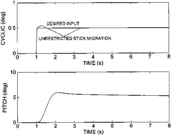
Fig. 6.29 Controls response of an AFCS with trim follow-up.

image173

image174

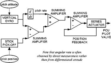
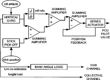
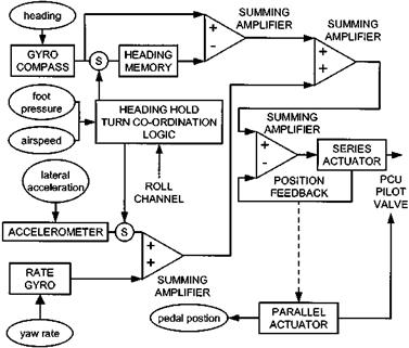
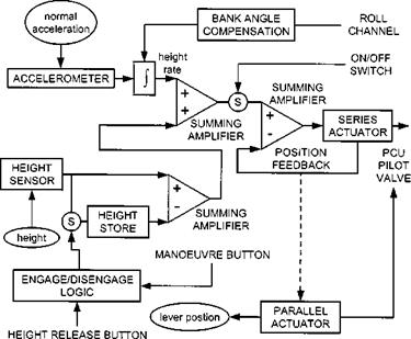
usually consist of a vertical gyro and at least a yaw rate gyro that feed signals to series actuators for stability with a gyro-compass feed for heading hold and an altitude sensor (barometric or radar) for height hold. Although four-axis follow-up trim is becoming increasingly popular, many in-service AFCS have parallel actuation only in the yaw and collective axes with conventional trim provided in the pitch and roll channels. Where autopilot modes, such as automatic transition to/from the hover, are provided the trim motors serve as parallel actuators. Schematics for each channel of a typical AFCS of this class are shown in Figs 6.31 to 6.34.

Differentiated attitude (or true angular rate) can be used to generate rate feedback in the pitch and roll channels but is inappropriate in the yaw channel due to the large voltage change associated with crossing magnetic north. Thus it is usual for AFCS manufacturers to use direct measurement of yaw rate (see Fig. 6.33). Heading hold is usually achieved by comparing the actual heading from the gyro-compass, with the value stored in memory at the instant of engagement of the hold. It is common for

image175

Fig. 6.31 Generic AFCS pitch channel.

image176

Fig. 6.32 Generic AFCS roll channel.

image177

Fig. 6.33 Generic AFCS yaw channel.

image178

turn co-ordination to be provided, as well as ensuring adequate heading hold up to the lateral velocity limits of the helicopter. Therefore, in addition to featuring parallel actuation to extend the authority of the series actuator, it is usual to find a sensor measuring lateral acceleration or sideslip. Some manufacturers choose to mechanize heading hold directly through a parallel actuator whereas others use the series actuator and follow-up trim.

The response of a rotor to a change in vertical velocity means that the heave axis of a helicopter is inherently stable and therefore it is not always necessary to have series actuation in this axis. A slow-acting parallel actuator is often sufficient to ensure adequate barometric altitude hold. A tighter control of altitude, often associated with a radar altitude hold, will require both series and parallel actuation in the collective channel. Altitude hold is analogous to heading hold in that the actual altitude is compared with a value in memory. Improved altitude keeping can be obtained by using integrated normal acceleration to generate a pseudo altitude rate. This pseudo rate will require bank angle compensation in turning flight since the accelerometer is fixed relative to the body axes whereas the vertical velocity relative to the earth is needed for altitude keeping. Engagement and disengagement of an altitude hold is often less complex than a heading hold system. Typically there will be an altitude hold release switch on the collective lever along with an on/off switch located within the AFCS control head. Some systems feature a ‘manoeuvre button’, also located on the collective, to allow rapid selection of a new altitude datum by the pilot. Whilst this button is depressed the altitude memory is continually updated with the actual measured altitude.

The requirement to provide turn co-ordination complicates the basic stability augmentation system. Heading hold and sideslip control are functions of the yaw channel but it is most natural for the pilot to initiate a turn by means of lateral cyclic stick deflection. It is therefore necessary for the AFCS to incorporate some linkage between the roll and yaw channels so that heading hold can be unlocked when the pilot moves the cyclic laterally or a bank angle above a certain threshold is sensed. Unlocking the heading hold is simply achieved by allowing the heading store to be updated by the current reading from the gyro-compass. In the low speed regime the pilot will need to re-position the helicopter laterally without initiating a turn and thus an airspeed switch is often needed. Simpler systems use foot pressure to make a switch on the yaw pedals as an indicator that the pilot wishes to commence a turn thereby obviating the need for any bank angle logic or airspeed switching. However even sophisticated turn co-ordination logic will require a sensor in the yaw circuit to enable the pilot to perform spot turns.

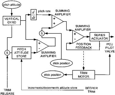
Although stick cancelling can be engineered to provide a convenient and satisfactory method of informing the AFCS that the pilot wishes to change the aircraft attitude it is not the only possible solution. Some systems (see Fig. 6.35), store the datum attitude in memory and arrange for the pilot to modify this memorized value by various means. For small attitude changes the pilot can use a beeper-trim to increase or decrease the stored attitude as well as changing the stick position. Alternatively, when making large attitude changes the pilot can depress a trim release switch, which in addition to removing the trim forces causes the attitude memory to be updated with the current measurement from the vertical gyro. It should be noted that the application of trim release will also temporarily remove rate stabilization since the open electro­magnetic clutch will prevent the series actuator from effecting control. Stick movement

image179

Fig. 6.35 Alternatives to stick cancellation – pitch channel.

without retrimming (against the spring feel loads) is used to open the attitude feedback loop allowing the pilot to manoeuvre around the datum attitude without updating this datum.

Trim follow-up systems

Some systems (Westland Sea King and Lynx) use only a combination of stick cancelling and pseudo-rate (differentiated attitude) feedback to provide a satisfactory control response and gust rejection. Whereas others are more complex, employing both attitude and rate gyros with force disconnects to alert the AFCS to an intended deviation from the current attitude datum. Ultimately, possibly even without the requirement to provide outer-loop modes such as airspeed hold or auto-ILS, the limited authority of series actuation will lead to some degradation of the long-term attitude-keeping performance. Whilst simply extending the travel of the series actuator would overcome this deficiency it is not a favoured solution since it would impact the safety case for the system (actuator runaways would have more severe consequences) and may degrade the control response characteristics due to excess damping. Usually a better alternative is to provide a mechanism that attempts to centralize the series actuators as they approach their end-stops thus ensuring that they operate with approximately full authority at all times. The key to a trim follow-up system is a device that can move the cockpit control thereby shifting the cyclic, collective or tail rotor pitch datum about which the series actuator operates. Usually the trim motor, which

image170

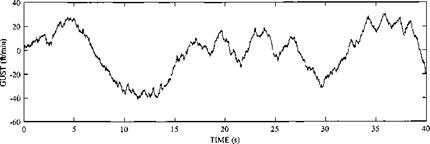
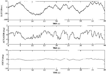
Fig. 6.27 Effect of trim follow-up on gust response.

doubles as the parallel actuator in the cyclic channels, provides this trim follow-up capability. Activating a trim follow-up system also requires a logic circuit that can determine when to send a drive signal to this actuator. Since the series actuator position is often measured in order to provide a feedback signal to the actuation circuit, and possibly drive some form of cockpit indication, it is a simple matter to use this data to trigger movement of the parallel actuator/trim motor. As expected the application of trim follow-up improves gust rejection by simply increasing the effectiveness of the series actuator (compare Fig. 6.27 with Fig. 6.25).

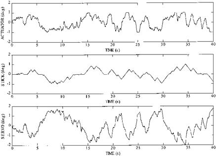
Figure 6.28 confirms that trim follow-up extends the authority of the system by showing that the activity at the main servo now exceeds +1°. Figure 6.28 also highlights one of the potential disadvantages of trim follow-up systems for some pilots: unnatural and unexpected control activity in the cockpit. Although the pilot has selected a trim position for the desired airspeed the follow-up system causes the cyclic stick to migrate fore and aft depending on the degree of extra authority required by the series actuators to counter the atmospheric turbulence. Since the pilot has not selected a true autopilot mode he may be operating ‘hands-on’ and could find the uncommanded stick movements disconcerting.

Inappropriate stick forces during rapid control movements are perhaps of greater concern than stick activity during trimmed flight in turbulence. Suppose the pilot makes a small aft step input. Initially the series actuator will move in the same direction. This may cause the trim motor to activate driving the stick further aft. A short time later the aircraft starts to pitch-up and the rate feedback signal, augmented eventually by the attitude feedback signal if it is still retained, causes the series actuator to oppose the initial input. If this reversal is sufficiently large the trim motor may again activate but this time the stick will be driven in a direction opposite to the

image171

Fig. 6.28 Effect of trim follow-up on main servo travel.

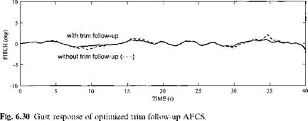
original input. Eventually the series actuator will approach null and the trim motor will be signalled to drive the stick back to the position selected by the pilot at the start of the input. If the pilot grips the control firmly during this process he may notice a disconcerting change in the feel of the control as the trim system is moved relative to the control. Problems with control response can be alleviated by reducing the trim rate. A slower acting trim motor is less likely to give perceptible stick migration during rapid controlling and will reduce the risk of catastrophic damage following a hard – over of the trim system. Rapid removal of unwanted stick forces following a gross change in aircraft attitude, a possible failing of a slow trim system, may be achieved by a trim release switch. Figure 6.29 shows the step response of an AFCS with a slow- acting trim follow-up system and Fig. 6.30 confirms that the gust rejection is still satisfactory.

Note that the ‘unrestrictedstick migration’ portrayed shows the hypothetical situation that would arise if the pilot made a step input and then allowed the stick to move in his hand as a function of the trim follow-up requirements. In reality the pilot would maintain a firm grip on the stick commensurate with the type of input made, in which case he would feel a change in the stick forces instead.