Category Helicopter Test and Evaluation

Lateral static stability

The lateral static stability can also be degraded by the addition of external stores or floats. In this case the increase in side area below the mid-point of the fuselage may produce a large destabilizing contribution to the overall lateral stability. Weak positive to neutral static stability may result with consequently poor sideforce cues. If this characteristic occurs with poor directional static stability the pilot may find it very difficult to control sideslip. In addition weak lateral static stability will increase the workload required to maintain wings-level flight. Once again augmentation, this time in the form of roll rate feedback is likely to be the most cost-effective solution, although a bank angle hold may be necessary.

6.5.1.5 Control response

The control response of the helicopter will be of great concern to the pilot. If the response is poorly tuned to the role the aircraft may still have unacceptable handling qualities regardless of how well the stability deficiencies have been overcome. Generally the nature of the control response is a function of the rotor system fitted to the helicopter and only minor changes can be made via modifications to the mechanical characteristics of the cockpit controls.

6.5.2 Levels of augmentation

The term automatic flight control system covers a multitude of systems that are used to improve, or remove, the stability deficiencies described above. In addition the more sophisticated systems can improve, or tailor, the handling qualities and permit certain role manoeuvres to be flown automatically. The term AFCS will be taken to apply to all forms of stability augmentation and automatic flight path control.

Stability augmentation (or inner-loop) systems can be further sub-divided into systems that use angular rate information as their primary data source and those that rely on direct measurement of aircraft attitude. Typically rate-based systems are cheaper and simpler to design and are, therefore, found on small-to-medium sized helicopters. Attitude-based systems are often enhanced by a range of outer-loop modes, see below, and are found on larger helicopters or those aimed at single pilot IFR operation.

The autopilot, or outer-loop system, is a higher level of augmentation. As the name suggests it can be considered as an outer loop around a stability augmentation system that allows automatic control of flight path through the action of parallel actuators. Holds other than pitch and roll attitude will often be included such as heading, speed, height (radar and barometric) and vertical speed. Special modes may also be included: coupled approach, auto transition, ‘go-around’ and hover position hold.

Fly-by-wire (FBW) technology, for long the sole preserve of flight control systems for fixed wing aircraft, has flown successfully on several research rotorcraft and is being implemented on two helicopters (RAH-66 and NH-90) destined for full-scale production. As in fixed-wing systems FBW affords the helicopter FCS designer greater flexibility of design. This has been necessary to reduce pilot workload by providing a set of control laws and holds that are role suited, selectable and blended so that the most appropriate form of command and stability augmentation is available for each phase of the mission. This will enable the crew to devote more time to operating on­board sensors or weapons systems rather than piloting the aircraft. With FBW the flying controls need not be placed in the conventional positions as all piloting commands are passed through a flight control computer (FCC) by means of electrical signals. A sidestick and a small collective lever are alternatives to the conventional controls.

Lateralldirectional oscillation

The Lateral/Directional Oscillation (LDO) of a helicopter can be regarded as the lateral/directional equivalent of the longitudinal long-term mode. In most rotorcraft the LDO is very similar to the Dutch roll mode found in conventional fixed wing aircraft. Depending on the relative magnitudes of lateral static stability and directional static stability the Dutch roll will be either convergent or divergent, and highly oscillatory or deadbeat. The characteristics of the mode may also change markedly with flight condition as fin effectiveness can be strongly influenced by the skew angle of the main rotor wake. The ease of excitation, ease of suppression, the frequency, the roll-to-yaw ratio and the intended role of the helicopter will determine if the LDO can be tolerated without augmentation.

6.5.1.3 Spiral stability

For rotorcraft, the aerodynamic factors contributing to good LDO characteristics will often degrade the spiral stability. At high angles of bank the weight of the vehicle will produce a large into-turn moment which may overcome the existing aerodynamic forces thus degrading stability still further. It may be impossible to endow the helicopter with acceptable LDO and spiral mode characteristics throughout its flight envelope without resorting to artificial aids.

6.5.1.4 Directional static stability

The directional static stability characteristics of a helicopter can be poor, especially at low values of forward speed and low angles of sideslip. The main cause of this phenomenon is the lack of adequate fin effectiveness at low values of lateral velocity or total velocity. Blanking of the fin by the fuselage or inadequate tailoring of the main rotor wake are typical reasons. The resulting low values of Nv may lead to poor natural sideslip control that may be unacceptable in certain missions, such as ground attack. Directional stability may be further degraded if there is a large amount of side area towards the front of the fuselage, such as when external stores are carried or floats fitted. Aerodynamic fixes may be difficult to engineer and are usually expensive to install. Often the most suitable solution is stability augmentation in the form of a yaw damper or the provision of a heading hold.

AUTOMATIC FLIGHT CONTROL SYSTEMS

Helicopter automatic flight control systems (AFCS) are many and varied. In some cases they provide slight compensation for the ‘raw’ aircraft characteristics whereas in others these characteristics are completely masked (so-called superaugmentation) and the pilot’s perception of the aircraft is solely based on the nature and performance of the AFCS. This section is intended to give the reader an understanding of rotorcraft AFCS without describing in great detail all the various systems currently available or envisaged for the future. After a brief review of the important stability characteristics of helicopters, and a discussion of the levels of augmentation available, the major system components are described. The section concludes with descriptions of generic systems.

6.5.1 Helicopter stability deficiencies

Before discussing AFCS in detail it is instructive to review the important stability characteristics of helicopters. The inherent stability problems associated with generat­ing lift and thrust from an ‘edgewise’ rotor mean that only the lightest and cheapest helicopters on the market are unaugmented.

6.5.1.1 Longitudinal long-term mode

The longitudinal long-term mode contributes to the multi-axis oscillation, the ‘falling leaf mode’, found in the hover. This mode is usually unstable and will only be satisfac­tory if the time to double amplitude (T2) and period are sufficiently long that mission workload is tolerable. In forward flight the long-term mode is similar to the classic phugoid found in conventional fixed wing aircraft, although with greater changes in pitch attitude. Depending on the characteristics of the horizontal stabilizer and, there­fore, the degree of speed stability, the mode can be either convergent or divergent. Once again the rate of divergence, the period of the motion and the intended role of the helicopter will determine if this mode can be tolerated without augmentation. In some extreme cases, such as a semi-rigid rotor at high speed, this mode may become aperi – odically divergent, in which case augmentation will be imperative.

6.5.1.2 Manoeuvre stability

The manoeuvre stability of all helicopters will degrade to instability at high speed and high load factor due to the progressively greater destabilizing effect of the main rotor. Therefore, for helicopters required to operate at high load factors, some form of augmentation will normally be fitted. The greater pitch damping provided by rate stabilization is a possible solution, as is the use of a programmable stabilizer.

Basic power flying control systems

A basic power control system consists of a pilot valve/main servo arrangement. The pilot’s input is transmitted by mechanical means to the pilot valve. Hydraulic fluid pressure controlled by this valve causes the body of the servo to move in the required direction and this movement acts on the rotor blade through the normal pitch change mechanism. As with all servo mechanisms, there must be some feedback to stop the movement at the required position so that the input at the rotor head is proportional to the pilot’s input in the cockpit. Typically this is achieved by arranging for movement of the servo body to cancel the pilot valve displacement. The force required to move the pilot valve is small with the servo providing the power to move the rotor blades against aerodynamic and inertia loads. Thus this basic system provides a large power amplification.

The basic powered flying control system reduces the pilot’s workload but has no force feel, apart from inherent friction in the control runs. Thus the pilot is unable to release the controls to carry out other tasks, as they may move under gravitational or vibratory forces. In addition, there is no cue to tell the pilot how far the control has been moved. There is, therefore, a requirement to provide control retention and control centring force cues, which ideally can be trimmed over the full range of control movements required for flight. Below is a list of additional devices that may be fitted to tailor the control characteristics to the pilot’s needs, to the aircraft and its roles.

(1) Friction control device. A friction control device is the simplest addition to a powered flight control circuit. It normally employs an adjustable sliding friction device acting on the control or control rods. The major drawback of this device is that the force required to overcome static friction (stiction) is usually greater than that required to overcome the sliding friction with the control in motion. This tends to lead to jerky control movements and possible overcontrolling, although the device does provide control retention. With wear and the ingress of dirt and oil, this system is prone to binding and the generation of non­linearities in the force required to move the control over its full range, all of which is not conducive to the smooth and precise control of a helicopter. Friction devices are common on the collective pitch control where small and rapid movements are not normally required.

(2) Spring feel and clutch systems. The spring feel and clutch system provides a synthetic force gradient about the trim position, control centring, and an instantaneous trimming capability. The clutch is usually disengaged by a trim release button on the pilot’s control. Fail-safe operation tends to vary from aircraft to aircraft, some leaving the controls free or at a set trim position. One problem with this type of system is the potential for stick jump. If, while holding a control force against the spring, the clutch release is operated, the force resisting the pilot drops to zero faster than the pilot can relax his applied force so the stick will jump. Very light forces do not present a problem in this respect but experience shows that forces in excess of 1 daN tend to produce a rapid jerk of the control when the clutch is released.

(3) Cyclic ‘beeper trim’ system. This system meets the requirements for positive control retention, force cues and the ability to trim the control over its full range of movement. In most aircraft the system can be disengaged by the use of the trim release button which releases an electromagnetic clutch between the motor and the spring box. The trim rate has to be tailored to the control gearing, the aircraft’s stability characteristics, control force gradients and the mission of the aircraft. For example, for a given aircraft and gearing, a slow trim rate would be ideal for instrument flight, giving almost vernier adjustments, but this rate would be unsuitable for more aggressive manoeuvring particularly if high force gradients were used. In this latter case, aggressive manoeuvres would require the pilot to make large control displacements leading to high control forces unless the trim rate was fast enough to relieve them quickly.

(4) Viscous damper. Rate damping, in the form of a viscous damper is used in a number of control systems to limit the rate of application of a control for stress reasons or to prevent a pilot induced oscillation in some mode. The character­istics produced by a viscous damper can enhance or detract from controllability depending on the combined effects of the damper, friction, breakout force and force gradient. From a pilot’s point of view a rate damper gives him a sense of how fast the control is being moved and tends to remove some of the jerkiness from control movements. A damper may also be used to prevent stick jump in a spring feel and clutch system.

Types of helicopter flying control systems

6.4.1.1 Manual flying controls

This system uses a direct mechanical link, in the form of rods, bell cranks, and cables, between the pilot’s controls and the pitch change linkage. Exceptions are some of the Kaman helicopters where the pilot’s cyclic and collective controls are connected to servo tabs on the main rotor blades. Aerodynamic forces acting on the servo surface cause flap pitch changes on the rotor blades. Control systems that move a pitch change linkage have been found to be rather inflexible with some poor control characteristics especially at high AUM. They have been found to be unacceptable on helicopters with AUM in excess of about 10000 lb (4500 kg). These systems, however, are still fitted to light helicopters and to some heavier machines as a reversionary mode in the event of failure of the powered control system. Refinements can be fitted to improve the characteristics:

• Spring bias units to reduce steady state cyclic control forces.

• Spring arranged to provide a pre-load on the collective lever or a more complex arrangement of levers and weights attached to the rotor head to reduce collective pitch loads.

• A one-way hydraulic lock unit or damper to reduce fluctuating loads fed back from the rotor head to the pilot’s controls.

6.4.1.2 Powered flight controls

Most modern military helicopters are fitted with either simplex or duplex power control systems of varying complexity to suit the characteristics of the aircraft and its roles. The system is a remote position, closed loop servomechanism and to be satisfactory must meet the basic requirements of such a system. It must have a satisfactory performance, with good response and stability characteristics and it must be safe and reliable.

It is important that the performance of the system is such that the servos are capable of producing the necessary thrust to overcome the blade pitching moments under all conditions of flight otherwise it is possible that control of the rotor will be lost during some critical manoeuvre. Usually the required servo performance can be obtained by suitable design, since the thrust produced by a hydraulically operated servo is propor­tional to the cross-sectional area of the piston and the effective pressure of the hydraulic fluid. For precise control the response characteristics of the servo must be appropriate for all conditions of flight. The rate of movement required from a servo will depend to some degree on its function. Servos required to follow pilot’s inputs and stabilize the helicopter in the cyclic channels will be rapid; slower-acting servos can usually be tolerated in the yaw control and collective circuits. To obtain satisfactory control, the lag between a demanded input and the resulting movement must be small otherwise the pilot will complain of a lag in the response of the rotorcraft.

Since powered flying controls are basically high gain servo mechanisms, it is necessary to ensure that the system is a stable one. This is usually achieved by designing the system with a high natural frequency, the inertia of the moving parts being made small in relation to the thrust produced, and by connecting the servo unit output direct to the pitch change mechanism of the rotor blades. The aerodynamic loads from the rotor that have to be overcome by the servos are oscillatory in nature. Great care is therefore taken to ensure that these oscillatory loads are not fed back into the control system by making it as stiff (irreversible) as possible. For obvious reasons, powered flying control systems must be made as safe and as reliable as possible. A single system may be used with a manual reversion capability but with the increased AUM and higher speeds of modern aircraft, the trend has been to fit multiplex control systems for safety.

FIG power contribution at autorotative rotor speed

Following a power failure the manufacturer may recommend a suitable value of rotor speed at which the subsequent autorotation should be flown. The value of NR will be chosen such that it is unlikely to exceed limits, the autorotative performance is good and the rotor contains sufficient energy to perform a safe landing. Despite some manufacturers only specifying a range of permitted rotor speeds it will still be necessary to target a particular NR or collective pitch for the purposes of quantifying any power contribution in FIG.

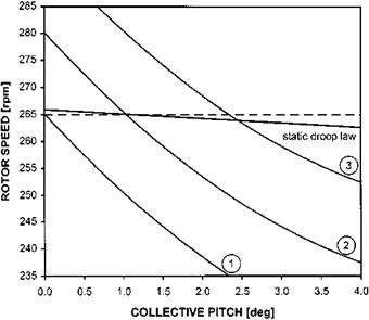
Figure 6.15 shows three possible positions of the autorotative NR versus collective pitch trend relative to the static droop law. In each case a target autorotative NR of 265 RPM has been assumed.

Curve 1. The value of rotor speed generated by an autorotative descent is always below the value demanded by the engine governor. In a power-off descent the pilot will have to lower the collective lever fully to set a NR of 265 RPM. In a FIG at the same collective position the rotor speed demanded by the governor is higher at 267 RPM. Consequently there will be a power contribution in FIG, as the rotor will be driven up to this value by the engine. Alternatively the pilot could raise the collective to around 1° CP and set the target NR of 265 RPM thereby increasing the power

image157

Fig. 6.15 Power contributions at autorotative NR.

contribution. In either case there will be a noticeable difference between the rate of descent power-off and in a FIG.

Curve 2. At a higher AUM or density altitude the NR that can be generated by the ROD is higher and in this situation the governed rotor speed and power-off NR are identical at the CP required to set 265 RPM in autorotation. Thus there will be no power contribution in a FIG and the rate of descent will be the same as in the autorotative case. Since the rotor speed in each case is identical if the pilots sets 265 RPM in a FIG then although the torque will be zero there will be no NF/NR split.

Curve 3. At still higher values of AUM or density altitude the situation becomes clearer. In setting 265 RPM, even with the engines operating at flight idle, the rotor speed can be fully sustained by ROD alone and therefore no power contribution is required. The pilot will need approximately 2.3° CP to set 265 RPM and if the engines were at flight idle he would notice that as well as zero torque being indicated, the free turbine would be governed at approximately 263.5 RPM so a clear NF/NR split would be discernible.

It is perhaps worth reiterating that despite the variations of autorotative NR with AUM and density altitude if during a FIG there is zero torque indicated and a clear Nf/Nr split then there can be no power contribution and the FIG is fully representative of a true autorotation.

6.4 FLIGHT CONTROL SYSTEMS

Early helicopters had fairly simple control systems, consisting of cables and rods connecting the pilot’s controls to the pitch change mechanism at the rotor head. With these early manual systems, the pilot had to apply the necessary force to overcome the aerodynamic loads on the rotor blades, with only some mechanical advantage to aid him. For this reason blade design had to be optimized to maintain nearly constant blade pitching moments over a wide range of collective pitch angles and rotor RPM. These blades were produced in matched sets and were usually of tapered profile and symmetrical blade section. These types of blades presented problems in quantity production and an attempt was made to use metal blades of constant chord which were easier to mass produce, but the control forces were generally unacceptably high. These problems and the growth in AUM led to the widespread adoption of powered controls for helicopters.

Flight idle glide

6.3.7.1 Flight idle setting and rotor rigging

The speed of the engine/gas generator at flight idle (the minimum speed to which it will fall with the collective lever fully lowered) is a compromise between two require­ments. It must be high enough to permit good initial acceleration without risk of surge and low enough to avoid a large power contribution (and therefore rotor overspeeding) when minimum collective pitch is selected. Most governors feature an adjustable minimum flow by-pass to prevent the governor cutting off all the fuel to the engine/ gas generator in the event of a transient overspeed. The by-pass adjuster is used to vary the shape (and hence gain) of the governor’s droop law especially at the low end of the law. This enables the minimum NG in FIG to be increased to achieve stall-free engine acceleration at the expense of increasing the likelihood of a power contribution.

So far in our study of governor characteristics only the upper part of the droop law has been considered. Attention must now be turned to the lower part of the droop law that represents FIG conditions. Although stability within the control system is still important a further factor must also be taken into account: the ease with which the pilot can set a desired rotor speed at low torque. Some droop laws feature a ‘knee’, that provides a lower gain at low torque in an attempt to meet this requirement.

6.3.7.2 Power contribution in flight idle glide

In many rotorcraft it is not practical to retard the throttles when practising auto­rotations or ‘forced landings’. Therefore, for realistic training flight idle glides should

image155

Fig. 6.13 Static droop/autorotation characteristics – FIG power contribution.

be representative of a true autorotation from the perspective of NR, rotor speed control and ROD. To achieve this the power contribution from the engine(s) must be zero. The characteristics of the rotor system, the engine and the engine control system may prevent this condition from being achieved. For the purposes of this discussion a FIG is a descent with engine condition levers ECL(s) forward and an autorotation is a descent with the ECL(s) retarded or with the engine(s) shut down.

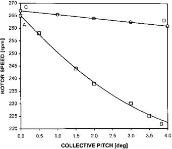
During a stabilized FIG, or powered descent, the engine and a component of the ROD will maintain the rotor speed. On the other hand in an autorotation at a given AUM, airspeed and density altitude there will be a fixed relationship between the collective position and NR. At a constant airspeed in autorotation the rotor speed achieved at a given collective position will the maximum that can be generated by ROD alone, see line AB in Fig. 6.13. At the same conditions in a FIG there will also be a fixed relationship between collective position and NR. This will be the same as the static droop plot for the same flight condition (line CD). In a FIG if the rotor speed demanded by the governing system is greater than the NR that can be generated by the ROD, the engine will, as shown in Fig. 6.13, drive the rotor to the required speed. Consequently there will always be a power contribution in FIG even with the collective lever fully lowered.

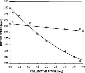
The magnitude of any power contribution in FIG is not fixed as the autorotative relationship will vary with AUM, density altitude, airspeed and rotor rigging. The by­pass adjuster and other elements within the engine control system may be used to alter the static droop law. If the relative position of the autorotative NR line and the static droop law are as shown in Fig. 6.14, the response of the rotor to changes of collective pitch in a FIG will be different. At point E the ROD is capable of driving the rotor to the required NR and, therefore, there will be no power contribution from the engine. Note that at point E torque will be zero and NR will be at the value defined

image156

Fig. 6.14 Static droop/autorotation characteristics – no power contribution in FIG.

by the low power end of the static droop law. For the configuration in Fig. 6.14 as the collective pitch is lowered below 1°, rotor speed will follow the line EA whilst NF will follow the line EC. Thus in this flight regime NR and ROD will be the same regardless of the position of the ECL(s) and there will be a discernible NF/NR split. Therefore a FIG descent will have the same flight characteristics as a true autorotation.

Variation of static droop with airspeed

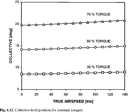
Having seen how the collective lever position varies with airspeed in level flight and with airspeed at constant torque it is now possible to surmise the effect of collective anticipation on the static droop recorded during climbs and descents at a range of fixed airspeeds. First the variation of collective position with airspeed, for constant torque, can be expanded for a range of torque values, see Fig. 6.12.

Now consider the basic function of collective anticipation; as the collective lever is raised the NF datum is increased in order to compensate for static droop. Suppose that for the example helicopter the standard rotor speed is 330 RPM and that with the lever fully lowered (0%) 0° of collective pitch is applied. Now assume that with the lever fully raised (100%) a collective pitch of 30° is set at the rotor head and that the basic static droop law causes a reduction of 20 RPM between 0% torque and 100% torque. Likewise assume that the engine control system designer intended to eliminate static droop by arranging that the NF datum be set to a rotor speed of 330 RPM with the collective lever fully lowered. As the lever is raised the NF datum is increased linearly to a maximum value equivalent to a rotor speed of 350 RPM. With these simple assumptions in mind it is now possible to determine the actual effects of the collective anticipator in flight. In the hover, 30% torque requires a collective pitch of 7.5° (a lever position of 27.2%). This will signal a NF datum equivalent to 335.7 RPM. The basic static droop law will result in a reduction of 6 RPM at 30% torque and so the rotor speed with collective anticipation will be 329.7 RPM. Similar calculations for 50% and 70% torque can be made; these are summarized in Table 6.1.

If the process is repeated for 140 KTAS different results arise due to the slightly

Table 6.1 Variation of rotor speed with torque – hover.

Torque (%)

Collective pitch (°)

Collective

position

(%)

Nf datum (RPM)

Basic static

droop

(RPM)

Resulting rotor speed (RPM)

30

8.5

28.3

335.7

6

329.7

50

14.1

47.1

339.4

10

329.4

70

19.8

66.0

343.2

14

329.2

Table 6.2 Variation of rotor speed with torque –

– 140 KTAS.

Collective

Basic static

Resulting

Collective

position

Nf datum

droop

rotor speed

Torque (%)

pitch (°)

(%)

(RPM)

(RPM)

(RPM)

30

9.0

29.9

336.0

6

330.0

50

14.9

49.8

340.0

10

330.0

70

20.9

69.7

343.9

14

329.9

different collective lever positions required for the same three torque values, see Table 6.2. If, therefore, a static droop assessment is conducted on this aircraft in the hover and at high forward speed the results will not be exactly the same due to the influence of the collective anticipator.

Flight at constant torque

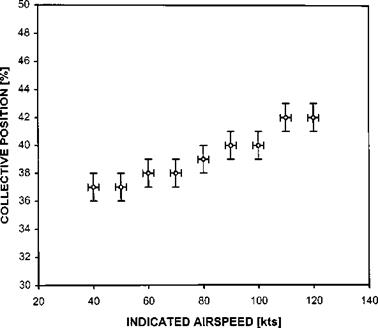
Flight at constant torque and in particular the collective position required to balance the forces and moments generated will give a clue to the rotor speed variation at differing airspeeds. If the helicopter is to fly at constant power, or torque, as airspeed is varied from the hover then it must adopt a rate of climb when the power for level flight at a given airspeed is less than hover power and a rate of descent when it is greater. The collective pitch required, for constant power, will depend on the thrust required to balance the weight, the vertical and horizontal drag and the degree to which compressibility and blade stall have affected the aerodynamic performance of the rotor. In general as the airspeed increases the drag penalty increases thus increased thrust is required to maintain the force balance. Note that although above minimum power speed the rate of climb required for constant power will be less; the increase in horizontal drag with airspeed more than makes up for the reduction in vertical drag and a net increase in thrust is usually required. Provided the rotor aerodynamic performance is not degraded with airspeed it can be assumed that the variation in collective lever position will match the thrust requirement. Flight test data, Fig. 6.11, can be seen to support these theoretical results.

image153

image154

Variations in the static droop law

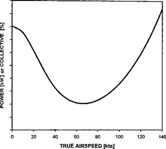
Whilst of obvious benefit to aircraft operation the installation of collective anticipation introduces a complication in the documentation of static droop as the datum RRPM is now dependent on collective position. However, the power required by the main rotor, although similarly dependent on collective pitch, is a function of airspeed, vertical speed and yaw pedal deflection/sideslip. Therefore it is possible for the stable RRPM to change with airspeed or ROC even though the collective position is unchanged. This phenomenon is best explained by example. Consider the variation of power required with airspeed for a typical conventional helicopter (Fig. 6.10). The ‘power bucket’ can be clearly seen as can the fact that at high forward speed the hover

image152

power can be exceeded. The variation of power can be translated into the collective position required for level flight. So even in level flight it is clear that the rotor speed will vary due to changes in the NR datum as the collective lever is raised and lowered.