Category Helicopter Test and Evaluation

Transient droop and overswing

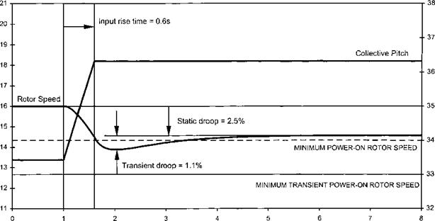
Transient droop or overswing is the variation in RRPM that occurs during changes in power initiated by a movement of the collective lever. Usually during an increasing torque demand there will be a rotor underspeed and during a power reduction the rotor will overspeed. Changes in NR occur because, in general, engine acceleration or deceleration cannot match the rates of change of collective pitch. Therefore during, say, power increases there will be a finite delay between the power demand (changed collective position) and the required power being produced (the gas generator reaching a new speed). During this delay the RRPM will fall to a figure which is below the steady state static droop for the new power. This extra reduction in RRPM is defined as the transient droop, see Fig. 6.9.

The delay is aggravated by the fact that a rotor speed error must develop before the gas generator will begin to accelerate. Eventually, just as with static droop, the transient droop may be large enough to put the RRPM outside its aerodynamic or mechanical limits. Without further modification of the control system, the only way of overcoming this is to limit the rate of collective pitch movement. This means in practice that the manoeuvrability of the helicopter is limited, and indeed some early machines were affected in this way. Other factors which affect the size of the overswing or droop are:

• governor gain;

• inertia of the main rotor;

• helicopter AUM;

• density altitude;

• acceleration and deceleration characteristics of the engine.

Подпись: 254 Helicopter Test and Evaluation
Подпись: Collective Pitch (deg)

w

T5

m


T3

Q>

Ф

a

</)


о


Time(s)


Fig. 6.9 Transient droop.


image151

Consequently rapid acceleration is a basic design requirement of modern helicopter engines. Two factors help to make rapid acceleration possible: low rotational inertia and high idle speeds (typically flight idle = 70% of maximum NG), which helps the engine tolerate a large degree of overfuelling. Alternatively, as discussed, a droop anticipator or compensator can be fitted which has the added benefit of reducing transient droop since it will start the gas generator accelerating without having to wait for a RRPM error. A further refinement is the generation of a signal proportional to the rate of change of collective. This signal is then used to open or close the gas generator throttle, depending on whether the collective is increasing or decreasing, so that the gas generator RPM starts to alter as soon as the collective is moved. Some fuel control systems are also configured with yaw pedal anticipator inputs.

Fixed turbine control systems

Clearly to meet the RRPM requirements a fixed turbine engine should operate on a constant speeding schedule. This confers the benefit of very fast acceleration times, since there are no inertia problems and massive overfuelling can be tolerated since the low power operating point is typically far from the surge boundary. The basic requirements for the engine control system have already been discussed and, in general, these requirements can be met more simply in a fixed turbine engine. As before the pilot changes the blade pitch by means of the collective lever but in this case, however, a small closed loop system acts to keep RRPM and engine speed constant. The Astazou 3N2 system (as fitted in the Gazelle helicopter) is a good example of such a system. In the governed range constant pressure is maintained across a variable metering valve, so that the fuel flow to the engine depends only on the position of this metering valve. The valve position is adjusted by a servo system controlled by a pilot valve that senses rotor speed. On some systems precise control and adjustment of RRPM may be vested in a speed select lever.

6.3.4.1 Mode of operation

If it is assumed that the engine is running in equilibrium when a collective pitch increase is demanded then it is clear that NR must fall initially. The pilot valve will therefore open and cause the metering valve to increase the fuel supply to the engine. The engine will then accelerate until the datum RRPM is restored. As it does so the pilot valve will gradually approach its null position at which point the metering valve is locked at its new more open setting.

Opening the control loop on the ground is again achieved by using a ‘lowest wins’ system similar in concept to that found on some free turbine engines (see Section 6.3.3.1). At ground idle the rotor speed will be very low (or zero) so the pilot valve and metering valve will be fully open. Under these conditions control of the engine is vested solely in a manually operated fuel valve (throttle). As this valve is opened to accelerate the engine to flight idle, the RRPM will increase until, with the throttle fully open, the pilot valve is nulled and the metering valve is governing the fuel flow. It is interesting to note that with such a system:

• There is no acceleration control fitted since it is not required in the flight range due to the constant speeding nature of the engine. Consequently the manual fuel valve or throttle must be handled very gently during acceleration from ground idle to flight idle.

• There is no static droop since the pilot valve always returns to the same null position. At equilibrium the rotor speed always balances the same spring force irrespective of the metering valve position.

• There will be some transient droop since a RRPM error is required before the pilot valve can move to adjust the metering valve. On some systems the transient droop may be so small that it is not discernible by the pilot. If so it is possible that torque spikes will result as the power output from the engine responds rapidly to the change in rotor speed.

• Since there is no static droop, each engine in a twin engine configuration can be delivering widely different powers and still be running at a common speed. Hence power matching is not usually feasible without the aid of some artificial stability system.

Droop reduction or cancellation

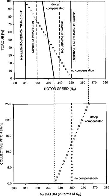
Suppose that for a particular rotor/engine/governor combination it is impossible to satisfy the requirement for adequate stability and respect power-on rotor RPM limits. In this situation a droop reducer must be fitted, the action of which is best described with reference to Fig. 6.8.

The upper chart shows the extent of the problem, before droop reduction is

_C

O’*


Ш

I—

<

ctr


о

_)

Lu


Z)

Li_


ROTOR SPEED (%)


image149

ROTOR SPEED (%)

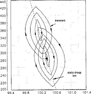
Fig. 6.7 Effect of high governor gain (10% collective pulse of 1 second duration).


image148

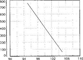
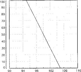
employed (see the ‘no compensation line indicated by open circles). If the amount of static droop shown (40 RPM) is required to ensure the governor has adequate stability it can be seen that at both high and low power demands (fuel flow rates) the rotor speed will pass outside the power-on limits. Since the pilot uses the collective lever to make power adjustments it is possible to change the rotor speed datum as the lever is moved. The lower graph shows a typical relationship. The combined effect of the basic

Static droop 40 rpm

image150

Fig. 6.8 Droop compensation.


static droop law (dependent on spring constant and governor mass) and the rotor speed datum schedule (dependent on the amount of spring pre-load) is shown in the upper chart (see the solid ‘droop compensated’ line). Now the rotor RPM stays within the steady power-on limits at all times. Although it might appear that governor gain has been increased and therefore its stability reduced in fact the governor stability is dependent on the basic droop law and is unaffected.

The effect of using droop reduction, or cancellation, on the rotor response can be described relatively easily. Consider the case when the pilot makes a pulse demand or a sizeable gust strikes the rotor. The behaviour of the rotor in this situation is in broad terms a function of the basic droop law and will be little different from the case when no droop reduction was applied. The full effect of droop reduction is seen more clearly when large and rapid power demands are made. When the pilot makes a large collective pitch demand he will cause the datum NF to increase as he raises the lever. Thus the fuel flow to the engine is increased as the power demand is being made rather than as a consequence of the governor sensing a reduction in rotor speed. Therefore droop cancellation will reduce the size of any transients as well as the difference between the stable rotor speed at maximum and minimum torque or collective pitch. The manner in which the transient behaviour of a rotor system is assessed and documented is described later. (Section 6.3.5 and 7.4.6.)

Static droop and governor gain

As mentioned earlier the use of a simple hydro-mechanical proportional governor to control rotor speed leads to reductions in RRPM as the fuel flow increases and vice- versa. This trend manifests itself as static droop, that is as the torque is increased from one equilibrium point to another the rotor will stabilize at lower and lower speeds. The amount of static droop can be expressed as:

Подпись:RRPM at minimum power — RRPM at maximum power _ 1 n(W

тТ"гТт^тГТ • • X 100%

RRPM at minimum power

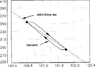
The change in fuel flow rate with RRPM (the static droop law) can be portrayed in a variety of ways and two typical plots are shown in Fig. 6.6. Although static droops as high as 10% have been used it should be remembered that for optimum rotor performance no change in RRPM, or isochronous governing, is desired. The problems associated with trying to achieve such governing by reducing the static droop are discussed below.

Governor gain is related directly to the amount of static droop. The gain is the change in fuel flow rate per unit change in RRPM. Thus a system with low governor gain will generate a high static droop and vice-versa. Consider now the effect of high governor gain, which is analogous to fitting a weak spring in a proportional governor. Although under static conditions the difference in RRPM between low and high torque settings will be low, the large changes in FFR that occur for small changes in RRPM can lead to an oscillatory and possibly unstable response. Figure 6.7 shows departures from the static droop law. Note that the oscillatory behaviour commonly associated with high gain is quite evident. (Lower chart in Figure 6.7.)

Selecting the best value for governor gain is a compromise between desired levels of stability and the need to remain within rotor limits during rapid power changes. However, the expected maximum rate of application of collective and available engine response must also be considered. Suppose the pilot moves the collective at a moderate

image146

ROTOR SPEED (%)

image147

POWER TURBINE SPEED (%)

Fig. 6.6 Static droop.

rate and the engine is capable of rapid acceleration then it is possible for the control system to produce a response with no transient. If on the other hand the pilot makes a very rapid demand a transient will result if the demand exceeds the acceleration capabilities of the fuel control system.

Free turbine governor characteristics

6.3.3.1 Simple governor operation

Most hydro-mechanical rotor governing systems are of the proportional type first developed for steam engines. When the load on the engine is increased (by the application of collective pitch) the rotor speed and consequently the power turbine speed falls. This reduction is used to signal an increased fuel flow to the gas generator. The resultant increase in power produced by the gas generator tends to restore the power turbine RPM and equilibrium is re-established when the torque produced by the power turbine equals the torque required by the rotor system.

In its crudest form the proportional governor contains bob-weights that are thrown out away from the axis of rotation thus generating a force that is proportional to the speed of rotation. This force is then used to close a fuel-metering valve against the action of a spring. Typically the free power turbine drives the bob-weights and their position regulates the amount of fuel fed to the gas generator. Consider a demand for more rotor thrust via an application of collective pitch. Initially the RRPM and hence the power turbine speed (NF) will fall, reducing the force opposing the spring thereby allowing it to force the valve open and allow a greater fuel flow. This increased fuel flow accelerates the gas generator enabling it to deliver more power and arrest the decay in rotor speed. Eventually when the force from the bob-weights once again matches the spring force, NR and NF achieve a new equilibrium condition. At this new equilibrium state a greater fuel flow (FFR) is required to meet the higher power and therefore the fuel valve must be open further than was the case at the lower collective pitch setting. Therefore FFR is inversely proportional to NF and the higher fuel flow rate is achieved at a reduced NF and consequently reduced NR. Clearly the greater the power demand, the further the fuel valve must be opened and the greater the reduction in the rotor RPM. This characteristic, termed static droop, leads to a steady reduction in rotor speed with collective pitch or fuel flow.

If this type of closed loop rotor governing system was functioning when the aircraft was on the ground with the rotors stopped, the system would detect a massive RRPM underspeed and demand maximum fuel flow or gas generator speed. The control loop must be broken, therefore, when the rotors are stopped. This may be achieved either electrically (as on the Rolls-Royce Gnome engine) or hydro-mechanically (as on the Rolls-Royce Gem engine). Some systems feature a single lever moving in a gate. Over the lower portion of the gate from ground idle (GI) to flight idle (FI) the lever controls the gas generator only. At FI a microswitch is made which feeds RRPM signals to the control system so closing the loop. From then on, from FI to maximum, the lever changes its function from one of controlling the gas generator to one of selecting the RRPM datum – hence its name a speed select lever (SSL). This system works well for a single engine installation. In the case of multi-engined helicopters the acceleration of the engine from GI to FI is often achieved via individual engine condition levers (ECLs), a separate SSL being provided for adjustment of the rotor speed datum.

In some hydro-mechanical systems the fuel flow to the engine passes through two variable area orifices in series; one controlled by the free turbine governor, the other by the gas generator governor and/or throttle. Overall system control is determined, therefore, on a lowest wins basis, that is the fuel flow to the gas generator will be determined by which of the orifices has the smaller opening. Alternatively a signal from the proportional governor driven by the free power turbine can be used to change
the gas generator datum speed with the gas generator governor controlling the fuel flow to the engine. In a typical two-orifice system at ground idle (GI) with the rotor stopped, there is no bob-weight force on the free turbine governor and under the influence of the governor spring its orifice is wide open, allowing unrestricted fuel flow. However, the gas generator throttle is in its minimum position and the gas generator governor has the minimum spring loading (corresponding to NG for GI) applied to it. As the ECL is moved, the gas generator throttle opens and at the same time a higher RPM setting is applied to the gas generator governor. The increased fuel flow through the throttle can now accelerate the engine up to the new higher gas generator governor setting. The free turbine governor orifice is still wide open and thus has no controlling effect. At some point in the acceleration process from GI, the rotor brake is released and a RRPM signal is applied to the free turbine governor. By the time the ECL is fully advanced, to a FI gate for example, this RRPM signal will have reached the governed range and a balance achieved with the spring force. The gas generator governor now has the maximum NG setting applied and since in general the engine speed demanded by the rotor governor will be less than that setting, the NG governor acts merely as a maximum gas generator speed limiter. In this way the control function is handed over from the gas generator via the ECL to the rotor via the free turbine governor.

Engine control system requirements

The characteristics of a gas turbine engine, particularly its characteristics during acceleration, are such that some form of engine control is essential if protection against surge is to be provided, and if the rotor RPM is to be maintained sensibly constant without creating an unacceptable workload for the pilot. In multi-engine installations it is also essential that the engine characteristics be matched. The engine control system is an integral part of the design of the whole helicopter and should, therefore, be related to its overall aerodynamic characteristics and its role. The major require­ments for an engine/control system for a gas turbine engine installation are: [13]

• If any part of the governor system is electronic, it must be free from electric – magnetic interference by both internal and external sources.

It may not be possible to meet all these requirements simultaneously. The emphasis placed on the importance of each requirement will depend on the operational roles of the helicopter. The above requirements may be summarized as follows:

• Steady state function. The system should provide closed loop rotor governing by altering the fuel flow to the engine to maintain the rotor speed constant or within allowable NR limits.

• Transient functions. The system should, when required, provide protection and set limits on free turbine speed, gas generator speed, temperature or rate of change of temperature and torque. Also the system should control the acceleration of the engine during start-up and transient operation.

• Control loop opening. The system should provide for the control loop to be opened under certain conditions.

Part of the control system requirement is commonly achieved using limiters:

• Nf limiter. The free turbine speed limiter (or overspeed trip) must be of the highest order of integrity. Following a break in the transmission system under load very high free turbine accelerations are achieved. To prevent a catastrophic turbine disk failure, which could occur within one second of the transmission failure, the fuel supply to the gas generator must be cut off within a very short time (of the order of 0.05 of a second). There is a danger associated with such a limiter, in that it could lead to fuel starvation of the gas generator during a routine transient NR overswing.

• Ng limiter. The gas generator maximum speed must be limited to prevent the compressor RPM exceeding the value which would produce a high NGIfQ stall or cause excessive compressor blade loading. In some installations a two-position stop is provided, to permit training at lower limiting power levels and thus conserve engine life (Puma, Super Puma).

• Temperature limiter. A temperature limiter is required if the combustion chamber and turbine systems are not to be damaged by excessively high combustion chamber temperatures. An example is the Protection and Control Unit (PCU) fitted to the Rolls-Royce Gem engine.

• Torque limiter. Originally it was thought necessary to include a torque limiter to ensure that the transmission torque limits were not exceeded. However, such a limiter caused the loss of several helicopters and these limiters are no longer used. Although by mishandling it is possible to overtorque the transmission it is now considered more cost effective to sacrifice it rather than lose the aircraft. Note, however, that the design philosophy behind the transmission system varies between manufacturers. In the West, it is general policy to provide the minimum transmis­sion power to do the task with acceptable margins, thus saving weight and cost, and leave the pilot to do the power limiting. On the other hand, the Russians have typically over-engineered the transmission such that it can cope with the maximum engine power available; thus the power limiter is the collective top stop. Collective pitch limitations are sometimes used as a compromise solution.

Fixed turbine enginelrotor characteristics

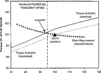
Figure 6.5 shows the torque versus RRPM characteristics for a fixed turbine engine/ rotor combination. As with the free turbine engine the rotor requirement is essentially a constant power line. The engine torque, however, unlike the free turbine engine, does not match the torque requirement of the rotor in that it is of the opposite slope. As discussed above this is because a reduced rotor speed implies a reduced engine speed and consequently there is less gas power for the turbine to convert. A limiting condition, known as the overpitch point, occurs when the reducing engine torque output (at maximum power) just equals the increasing torque requirement of the rotor. To the left of this point the system is unstable; as NR reduces further the rotor requires

Fig


image145

Rotor Speed (%)

Fig. 6.5 Fixed shaft engine characteristics.


image144

more torque but the engine produces less and less. Hence RRPM rapidly decays with a consequent loss of lift.

Overpitch can easily be induced by demanding too much power – collective pitch – at too low a RRPM. The only way to recover from overpitch is to reduce collective and increase the airflow through the rotor, thereby increasing NR and bringing it back to the right of the cross-over point. This technique inevitably involves a large loss of height.

On the modern fixed turbine helicopter, RRPM control is achieved automatically by the engine control system. However, control systems are not perfect – if they were, an exactly constant NR could be maintained independent of any flight manoeuvres, and one could fit an engine that just met the torque requirement at this NR (dotted line in Fig. 6.5). In practice, allowances must be made for transient droop – there must therefore be a stable range of operating RRPMs to the right of overpitch – and so an engine must be fitted which has a torque output similar to that denoted by the solid line. When comparing this practical engine with the theoretical one it is clear, first of all, that the practical powerplant needs to be a more powerful device. At the same time all the potential power cannot be used, otherwise the transmission system would be overtorqued, and so the engine must be limited or downrated in some way. One other consideration is that this practical engine will always be operating at partial powers; that is at much lower temperatures and pressure ratios than originally designed. Hence the thermal efficiency will be reduced and the SFC higher. Briefly then, to achieve a satisfactory and practical RRPM range, the fixed turbine helicopter engine must be downrated to preserve torque limitations. For example, the Alouette 3 helicopter is fitted with a 649 kW (770 SHP) Artouste IIIB engine downrated to 425 kW (570 SHP). One advantage of the downrating is that a power margin exists that gives the aircraft similar performance right up to the altitude at which the engine becomes the limiting factor – normally above 15 000 ft (4500 m) – which is why rotorcraft like the Lama have such good high altitude performance.

Gas turbine engine and rotor characteristics

6.3.1.1 Rotor requirements

= * C I’5 s

Подпись: W pAV 2 Подпись: P Подпись: Q

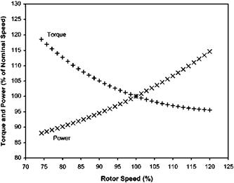
Sensibly constant RRPM is required both for mechanical reasons and for aerodynamic efficiency. If the RRPM is too high, Mach number problems are likely to be encountered on the advancing blade, whereas if the RRPM is too low, the stalled flow region on the retreating blade may become uncontrollable. If we restrict our consideration to the hover case then because we have removed the problems of asymmetry across the disk, the effect of variations in rotor speed on the power and torque required can be estimated quite easily using (see Figure 6.1):

image141

Fig. 6.1 Rotor requirements.

It can be seen from Fig. 6.1 that for a given thrust requirement a decrease in RRPM will have to be offset by an increase in the torque produced by the engine. Consequently matching the torque delivered by the powerplant to that required by the rotor will be simplified if the trend is similar. It should be noted that although a constant rotor speed is desirable, some variation in RRPM is likely particularly when the collective pitch lever is moved quickly. For optimum performance this transient should be as small as possible. However autorotative RRPM at minimum pitch should be as high as is possible to provide satisfactory engine-off landing characteristics.

6.3.1.2 Free turbine engine/rotor characteristics

The free turbine engine can be considered as two separate items: the gas generator and the power turbine. This is because in this type of engine the nozzle guide vanes at the front of the power turbine are always run in a choked condition (that is the flow Mach number equals unity at the throat of the nozzle guide vanes (NGVs)). Con­sequently the behaviour of the power turbine will not affect the performance of the gas generator. Thus the area of the choked NGVs will fix the position of the gas generator working line and the power turbine is supplied with a flow of high-energy gas that it can absorb at any combination of speed and torque. To understand how the overall engine characteristics are achieved it is necessary to consider the separate characteristics of the gas generator and of the power turbine.

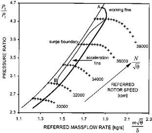
Figure 6.2 shows a typical compressor characteristic curve for a gas generator together with the operating or working line (which as has been seen above is positioned by the area of the power turbine’s NGVs). The stall margin is represented by the separation between the surge boundary and the working line. Points A and B indicate the areas where problems can be anticipated. Point A, the high NG/-J9 cross-over point, can usually by avoided by controlling maximum NG; but this point can give rise to problems under high altitude, low temperature conditions (low V9 values). On acceleration the stall margin at point B will be reduced as the acceleration line will

image142

Fig. 6.2 Compressor characteristic.

always be above the steady working line. A situation like that at B usually causes the difficulties associated with rapid engine acceleration requirements. Inlet guide vanes (IGVs) and/or bleed valves are used to increase the stall margin, but there are still likely to be limits set on the maximum rate of acceleration. Rapid increases in the combustion chamber pressure due to overfuelling must be controlled otherwise downstream choking may reduce the compressor air massflow rate and hence cause surge.

In some systems a compressor delivery pressure switch is incorporated that limits the fuel flow if the rate of increase of pressure is too high. The response rate of the gas generator is a most important factor when considering recovery from autorotation and although the gas generator of a free turbine engine is inferior in this respect to a fixed-shaft engine, modern gas generators fitted with anti-stall devices usually perform satisfactorily. Attempts to improve the power-to-weight ratio and the SFC will typically reduce the stall margin further, by moving the operating line closer to the surge line; acceleration thus becomes more critical. Any distortion of the compressor, casing or intake, caused either during manufacture or in flight (erosion or corrosion, FOD ingestion, ice build-up) will also narrow the stall margin.

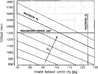
The torque versus speed (NF) curves for a typical power turbine are shown Fig. 6.3. The power turbine can operate anywhere in the area bounded by the maximum torque (a transmission limit), the maximum gas generator speed, and the maximum power turbine speed limits. The power produced at a given gas generator speed (NG) can be absorbed by the power turbine in any combination of torque and speed (NF) – hence the constant Ng lines are in fact lines of constant power. The pilot has two variables under his control: fuel flow via his throttle, which varies the gas generator speed (NG), and collective pitch that varies the torque demanded of the power turbine. Clearly if he has independent control of these two variables there is a distinct possibility that at some stage he will exceed the engine limits. For example, if he reduces throttle without

image143

Fig. 6.3 Free power turbine characteristics.

reducing the collective pitch the engine will surge, and it is imperative therefore that the two controls are interconnected so that this cannot happen. Two extremes are possible namely a constant speed power turbine/rotor schedule or a scheme that changes Nf so that at any gas generator speed the power turbine is operating at its most efficient. The acceleration obtained using the constant speeding schedule is usually better as power turbine and rotor inertia are not involved. However, the gas generator must still accelerate and as such is subject to the normal limitations of any jet engine. In early free turbine helicopters the rate at which one could apply collective pitch (effectively the aircraft manoeuvrability) was limited by the acceleration achievable by the gas generator. Modern engines are much improved in this respect.

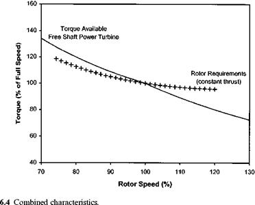
The characteristics of the rotor and of the free turbine engine have now been considered separately. Combining the characteristics of the two systems for a given gas generator speed (NG) and a given flight condition gives us torque versus rotor RPM curves similar to those shown in Fig. 6.4. It can be seen from this figure that the free turbine characteristic matches the rotor requirement. If the RRPM falls then the free turbine will automatically compensate with an increase in torque for a given flight condition, such as the hover. The aircraft may well sink and therefore require a further power increase – this is not considered in the graph.

ENGINE CONTROL AND ROTOR GOVERNING SYSTEMS

Cohen et al. [6.9] and Dixon [6.10] cover the basic principles and main design features of aircraft propulsion units. Here the characteristics of propulsion units suitable for use as helicopter powerplants are considered in relation to the particular requirements of this type of aircraft. Power units for shaft driven rotors of conventional configuration are discussed. Engines are usually mounted in or on the fuselage driving the rotor system via some form of gearbox. Blade mounted propulsion systems (tip drive) are not discussed although their existence should be noted. Tip drive systems have been produced in the past (Djinn, Rotodyne) but have not been considered practical for many years.

Power units for helicopters may be grouped into three main categories:

(1) Reciprocating piston engine system. The piston engine is now in a highly developed state and is very attractive, especially to manufacturers of small helicopters, mainly because of its cheapness. However, one of the major penalties with the piston engine is the need for a clutch in the transmission chain, to enable the engine to be started without having to turn the transmission. The need for the clutch incurs a weight penalty. There is also a growing trend away from AVGAS as a fuel due to its cost and volatility.

(2) Fixed shaft turbine engine system. The fixed shaft turbine engine is used in a helicopter in exactly the same manner as a piston engine. Thus, it is connected to the rotor via a clutch. It may also suffer from significant performance penalties. These are discussed briefly below.

(3) Free shaft turbine engine system. In a free shaft turbine engine system, a separate power turbine is included. This turbine is completely divorced from the turbine that drives the compressor. Thus, as there is no mechanical link between the power output turbine and the rest of the engine, there is no requirement for a clutch in the transmission system. The free power turbine may be held by a brake if there is a requirement to maintain the rotor blades fixed during initial start-up.

All gas turbine engines, whether of fixed or free shaft design, have several advantages over reciprocating piston engines. These advantages include: [12]

the same work as larger piston engined machines, or alternatively, for the same sized helicopter to allow a better performance.

• Fuel consumption. The specific fuel consumption of turbine engines approaches that of piston engines, and when run at full power may be even better. Since the power requirements of a turbine powered helicopter will be less, due to the lower engine weight, the total fuel used will be approximately the same. However, since gas turbine fuel is cheaper than piston engine fuel, the gas turbine engined helicopter will be cheaper to run than an equivalent piston engined machine.

• Reduced vibration. Since the gas turbine engine is a continuous flow machine the output from it will be uniform and hence vibration levels will be lower. This compares with the piston engined machine where the drive shaft is loaded in sequence by each cylinder of the engine.

Fixed-shaft engines are constant speed powerplants since they are directly coupled to a rotor that must operate at a substantially constant RPM. Power changes (or changes in torque) are therefore obtained only by changes in combustion temperature, the mass flow rate remaining approximately constant. Such an engine is capable of rapid changes in power, which is desirable in a helicopter especially during take-off and landing. However, as the operating speed of the turbine has to be set at a level that can be sustained continuously, there is inherent in the fixed shaft engine a power limitation which prevents the achievement of high power even for short periods. The fixed shaft engine is simpler than the free shaft engine, but the weight saving obtained as a result of this simplicity can be negated by the requirement for a clutch.

The major advantages of the free shaft engine, over one with a fixed shaft, are the elimination of the requirement for a clutch and the freedom to select a wide range of output power. The ability in the free shaft engine to vary both the combustion temperature and the air mass flow allows a wide power range to be achieved whilst the free turbine runs at a sensibly constant speed and therefore the free turbine engine is well suited to multi-engined helicopter applications. There is, however, one main disadvantage of the free turbine engine. Changes in power involve changes in the gas generator speed, including, therefore, variations in compressor speed. The inertia of the gas generator and avoidance of compressor surge will thus prevent power changes from being made as rapidly as would be possible with a fixed shaft engine.

Angle of attack and sideslip

Unlike conventional aeroplanes with wings rigidly attached to the fuselage the main rotor of a helicopter has pitch and roll degrees of freedom as well as the yaw freedom required by its rotation. As the rotor system generates most of the forces required for flight the fuselage attitude is, to a first approximation, simply governed by the balance of local aerodynamic forces and moments. Since stability axes are most often established relative to the fuselage it is evident that the velocity vector of a helicopter is rarely aligned with its longitudinal axis. The measurement of both angle of attack (a) and sideslip (P) is important for stability, control, performance and structural work. Some helicopter automatic flight control systems also use a direct measurement of sideslip as an aid to turn co-ordination.

The simplest form of instrumentation uses lightweight wooden vanes to measure the airflow direction relative to the boom attaching the vanes to the aircraft. Provided the vane is operating outside the wake from the rotor and any interference field associated with the fuselage or any external stores, the vane will align itself with the freestream airflow. The defection of the vane relative to the boom can be picked off electrically and presented to the crew as well as processed by any on-board data storage system. Depending on the orientation of the vane either angle of attack or sideslip can be sensed. Other systems determine a and P from the pitot-static system. A popular system fitted to test helicopters is the swivelling pitot-static probe which uses fins, like those fitted to a dart, to align the probe with the freestream flow. If correctly articulated and instrumented the angle of attack and sideslip can be inferred from the angular defection of the probe from the boom. An additional advantage of this device, provided there is no rotor wake interference, is that the true total pressure will be measured by the pitot. An alternative approach uses two fixed static pressure sources. If a static source is located on either side of the fuselage then in the presence of a sideslip the ‘into-wind’ source will over-read whilst the other may under-read. The subsequent difference in static pressure can be calibrated to give a measurement of sideslip.

6.2.2.2 Low airspeed

Low airspeed information is required for two reasons: firstly for test purposes to either ensure that the helicopter is in a true zero-wind hover or to provide accurate low airspeed so that its effect on handling and performance can be investigated; secondly for operational reasons to provide wind speed and direction information for improved weapon delivery. Thus there arises a subtle distinction between a ‘hovermeter’ and a true low airspeed sensor. A hovermeter is simply a device that accurately indicates the zero airspeed condition whilst giving the pilot a general indication of airspeed away from this condition so that he can bring the aircraft into the hover. A low airspeed sensor on the other hand delivers accurate airspeed information throughout the whole low speed envelope of the helicopter.

Simple hovermeter systems use a cranked boom or vane attachment that is aligned vertically to sense the direction of the downwash from the main rotor. Appropriate calibration is used to determine the vane angles, relative to the vertical, which are associated with a true zero-wind hover. Alternatively if the vanes are located sufficiently far below the rotor it may be satisfactory to assume that a true hover is indicated by each vane being aligned in a purely vertical direction.

Practical low airspeed systems generally use the rotational energy of the main rotor to boost the total pressure measured by a pitot probe. The Pacer system fitted to the AH-64A Apache consists of two pitot probes attached on top of the main rotor. When the helicopter is situated in a true zero-wind hover both probes sense the same dynamic pressure. However when the helicopter is moving or is hovering out-of-wind there will be a sinusoidal time-variation in total pressure and a phase difference between the readings from each probe. This time variation and phasing can be used along with the rotor speed and the mean pitot reading to determine the speed and direction of the airflow relative to the helicopter. If correctly calibrated a system like Pacer can also be used to measure sideslip in forward flight for test purposes and by the AFCS to enhance turn co-ordination. Another system called HADS (Helicopter Air Data System) which is fitted to the AH1 Cobra and the AH-64D also uses the dynamic pressure associated with the rotor wake but in a different manner. The HADS probe is a gimballed pitot-static probe that is located below the main rotor. It works on the principle that the main rotor wake strength and direction at any point below the rotor disk will vary with differing airspeeds and wind directions. Thus if a matrix of data points are coded into the system it is then possible for a given measurement of HADS probe angle and pitot pressure to be used as an indication of airflow relative to the aircraft. As with Pacer suitably calibrated HADS have been used to gather air data for test purposes. (See Section 3.5.6 for details of other systems.)

6.2.2.3 Temperature

A thermometer works by the transfer of heat energy from the medium under test to the temperature sensing element (bulb or thermo-couple). The local air temperature measured by an airborne probe will be higher than the ambient static temperature since the air will be necessarily slowed around the sensor. If the flow is completely halted and the temperature sensor is ideally screened then it can be assumed that the stagnation or pitot temperature will be measured by the thermometer and the compressible Bernoulli equation can be applied:

T = T [1 + 1-1 M Л

Angle of attack and sideslip

This equation can be re-written to replace Mach number with true airspeed:

Assuming air is a perfect gas (y = 1.4 and R = 277 J/kg K):

T = t + I______________ —________

p A + ‘ 1.4 X 287

Currently helicopters rarely exceed 200 kts and typical cruise speeds are closer to 100 kts (approximately 50 m/s). Thus the temperature measured by a perfect pitot- type probe would be no more than 5 K above the true ambient value and would usually be closer to 1 K greater than TA. Also noting that practical temperature probes do not fully decelerate the flow so that the recorded temperature is less than Tp it is clear why for all practical purposes the temperatures measured by in-service probes are assumed to be equal to the ambient value.