Category MECHANICS. OF FLIGHT

Flight at hypersonic speeds

In concluding this subject we must not leave an impression that once we have conquered the problems of supersonic flight, we have finished. Far from it – no sooner do we learn to get through one region of speeds than another, with new problems to solve, opens up before us.

Rather strangely, too, there does not seem to be much argument about where the change takes place in this case – above a Mach Number of 5 we talk of hypersonic speeds instead of supersonic speeds. It doesn’t pay to try to see the sense of this rather extraordinary use of the English language, or perhaps we should say of Tatin and Greek, which makes hypersonic superior as regards speed to supersonic; nor shall we get very far if we try to discover just why the Mach Number of 5 is so significant; actually it is a number of dif­ferent factors that decides the issue, and that is far beyond the scope of this book.

To us hypersonic flight is simply supersonic flight – only more so. Here we are deep into kinetic heating effects with all the associated problems; at a Mach Number of 5 at about 61 km the temperature given by the formula is over 1000°C and by Mach 15 it has risen to over 10 000°C. The actual tem­peratures are found to be rather lower, but not so much lower as to give any real comfort!

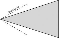
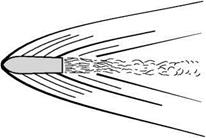
Mach Tines are inclined at very acute angles; Fig. 12.27 shows the shock waves and Mach Tines over a double-wedge section at a Mach Number of 10, and Fig. 12.28 is sketched from a photograph of a bullet moving at the same Mach Number. These suggest an arrow type of aircraft as being most suitable (Fig. 12.29).

One feature of hypersonic flow is a thickening of the boundary layer and an increased importance of the nature of the flow within the boundary layer.

Aerofoil shape seems to matter even less than in supersonic flight; lift and drag coefficients tend towards a constant value as the Mach Number increases.

Подпись: Mach number =10
Flight at hypersonic speeds

An interesting aspect of this part of the subject is the wide variety of exper­imental methods used to investigate it – arc-heated jets, gun tunnels, shock tubes, shock tunnels, hot shot tunnels, models moved by rockets or guns, and ballistic ranges; names that are all to some extent descriptive of the methods

Flight at hypersonic speeds

Fig 12.27 Hypersonic shock and expansion waves

Flight at hypersonic speeds

Fig 12.28 From a photograph of a bullet moving at Mach 10

Fig 12.29 Arrow-head: shape of the future?

employed, each of which would need a chapter to itself. Mach Numbers of 15 can be achieved in still air on ballistic ranges, and even more if the projectile is fired against the airflow in a wind tunnel.

But even hypersonic flow is not the end; at Mach Numbers of 8 or 9 some­thing entirely new begins to happen – molecules, first of oxygen, then at even higher speeds of nitrogen, dissociate, or split into atoms and ions, thus changing the very nature of the air and its physical properties (another phenomenon that is experienced by space-ships on re-entry into the atmos­phere, and which affects radio communication with them). At this stage there are possibilities of the control of the flow by electro-magnetic devices.

And so it goes on. Nothing, so far, suggests an end. Figure 12.30 shows how speed records have gone up – and up – and up.

Concorde

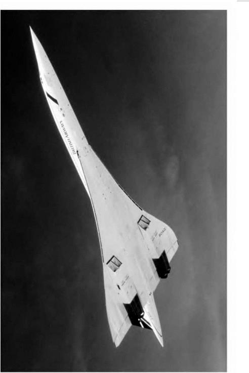
It seems fitting to conclude a discussion on the problems of flight, from sub­sonic to supersonic, with some comments on the design of the late lamented Concorde, because controversy on its cost, on its sonic boom and on its com­mercial viability have tended to obscure the cleverness of its design. Readers who have followed the arguments put forward in this book will surely be fas­cinated by some of its outstanding features. It would possibly be going too far to describe one of the main features of such a costly and sophisticated piece of equipment as simplicity yet, as we shall see, there is some truth in such a description.

The now familiar ogee (or double curve) plan shape of the wing gives both a large chord (27.7 m), with its advantages, and a large span (25.6 m), with its advantages.

The large chord means that although the wing is thin, very thin, from the aerodynamic (t/c) point of view (only 3 per cent at the root and 2.15 per cent outside the engine nacelles), and so has low wave drag; yet at the same time it is deep enough (83 cm) to give the required strength and structural stiffness, usually a difficulty with slender swept-back wings. The main advantage of the large span is the reduction of vortex, or induced, drag at all speeds.

The slimness of wings and body (the Boeing 747 Jumbo Jet is longer, higher and much fatter than the Concorde), and the limitation of speed to just over Mach 2, have kept down the temperature rise and made it possible to use alu­minium alloys, with which we have long been familiar, for most parts of the structure, instead of having to experiment with the more costly, and heavier, stainless steel or titanium alloys. The temperature rise in the structure is also reduced by using the fuel as a heat sink. The maximum landing weight is 1068 kN, and the maximum landing wing loading 4.786 kN/m2, less than that of many comparable aircraft.

The ogee plan shape has another advantage in that the stalling angle is so large that it is unlikely to be reached in any ordinary condition of flight; this is because the shape leads to the formation of leading edge vortices (without any vortex generators!), and so improves the flow in the boundary layer and gives smooth changes of lift and pitching moment with angle of attack.

On the wing there are no flaps, no slots, no tabs, no spoilers, no saw teeth, no fences, nor any other devices usually required for such a large speed range as from 65.4 m/s (at 18° angle of attack) to a true speed of 649 m/s. The only moving surfaces on the wing are the six elevons (combined ailerons and eleva­tors) which control both rolling and pitching – and very effectively too. The rudder has two sections, but is otherwise simple and conventional.

The large ‘leading edge’ vortices are useful when landing as lift continues to increase to large values with increasing angle of attack, the ‘lift boost’ and the ‘form thrust’ already mentioned in connection with highly-swept wings, and the large area of the delta wing gives a considerable cushioning effect when near the ground (two reasons for dispensing with flaps).

Perhaps one of the most interesting features, taking us back to one of the earliest ideas for adjusting trim is the movement of fuel between tanks, auto­matically between the main tanks for adjusting the centre of gravity during cruising flight and, under the pilot’s control, from forward tanks to a rear tank under the fin during acceleration to supersonic flight when the aerodynamic centre moves back, and vice versa when returning to subsonic flight.

Pilots report that it is only by looking at the machmeter that they know when Concorde is going supersonic.

Stability and control problems

In the previous chapter we considered some of the problems of stability and control at transonic speeds. Some of these still apply in the supersonic region, and control surfaces should be of the all-moving slab type, and fully power-operated. But whereas in the transonic range this applied mostly to the tail, in the supersonic range it can be applied also in all-moving wing tips to replace conventional ailerons, and even to an all-moving fin and rudder. Since the main plane may be nearly as small as the tail plane, it, too, may be movable to give pitch; in fact in some missiles it is not easy to decide which is the main plane and which the tail plane.

But there are also new problems at supersonic speeds because the inertia forces are so great that it is practically impossible to provide the inherent natural stability of the kind that is associated with such devices as dihedral and fin area. In order to be effective against the inertia forces the surfaces would have to be so large that the cost in weight and drag would be prohibitive – and this applies particularly at great heights where there is so little air density.

Another difficulty, which is especially applicable to military aircraft, is that pilot and crew have so much to do in looking after the equipment that they must be relieved as far as possible of flying the aeroplane.

Of course we have long been familiar with the automatic pilot, but the modern conception is very different from this – nothing more nor less, in fact, than synthetic stability and automatic control. Is the pilot then necessary at all? Strictly speaking, probably not, the aircraft can be controlled from the ground like a guided missile. But pilots can still do some things that instru­ments cannot, they can monitor the automatic systems, tell them what to do, investigate any failure and, if necessary, take over control.

Kinetic heating

We all know that friction increases temperature, an example of deterioration of energy from the highest to the lowest form (from mechanical energy to thermal energy), a natural process – and skin friction in the flow of fluids is no exception. We all know, too, that an increase of pressure, as in a pump, raises temperature – and the stagnation pressure on the nose of a body or wing is no exception. So when an aeroplane moves through the air it gets hot; some parts more than others, some owing to the temperature increase created by skin fric­tion, some owing to that created by pressure.

When, then, do we first come up against this? The answer is – when we first fly! But it isn’t serious? No – like many other things, it isn’t serious at low speeds. It has been said that aeroplanes made of wax melt at 300 to 400 knots, those made of aluminium at 1600 to 1800, those of stainless steel at 2300 to 2400 knots. Aeroplanes are not made of wax (wind tunnel models sometimes have been), but some are made of aluminium alloy, and some of stainless steel, and of other metals (such as titanium) and their alloys, and just because of this very problem. Nor can we afford to go anywhere near the melting point; metals are weakened long before that – and what about the passengers, and crew, and freight?

Bullets and shells certainly travel at speeds where heating is significant, but within limits it doesn’t matter whether bullets and shells get hot or not. Also their flight is not usually of very long duration, and it takes time for the surface to heat up. But meteors and satellites re-enter the atmosphere without any means of braking – and we know what happens to them, they get frizzled up. It is true that most manned space-craft have survived re-entry and more will be said about that in the next chapter. Let us at least consider what we can do to reduce heating effects.

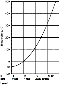
A very simple formula (V/100)2, where V is the speed in knots, gives a very fair approximation to the temperature rise in degrees Celsius. So what is merely a rise of 1°C at 100 knots, or 4°C at 200 knots, becomes 36°C at 600, 100°C at 1000, and 400°C at 2000 knots. That is how we discovered that the aeroplane made of wax would melt! Figure 12.26 shows rather more accu­rately local surface temperatures that may be reached under certain conditions at Mach numbers up to 4; these have been calculated from the formula t/T = (1 + M2/5) where t is the stagnation temperature, i. e. the temperature of air moving at a Mach Number of M being brought to rest, and T is the local tem­perature of the air; the figures relate to 8500 m where the local temperature is
—40°C. The temperatures shown in the graph apply to a laminar boundary layer; the temperatures are rather higher for a turbulent boundary layer. Moreover, at Mach Numbers above 2 these surface temperatures may be reached in a matter of seconds, and certainly within a minute or two, unless there is some method of insulation.

Many devices have been tried, and no doubt many more will be tried, in an effort to counter this heating problem. These devices may be classified under the following headings –

(a) To insulate the structure from the heat.

(b) To use materials which can stand the high temperatures without serious loss of strength.

(c) To encourage radiation from the surfaces and so reduce the temperatures.

(d) To circulate a cooling fluid below the surface.

(e) Refrigeration by any of the normal methods.

Подпись: 0 1 2 з 4 M 595 1190 1785 2380 knots Speed

As regards materials for the aircraft structure light alloys are suitable for Mach Numbers up to 2, or even higher for short periods. Between М2 and M4 titanium alloy may be the answer, but above 3 or 3.5 stainless steel is probably better as being more readily available.

Fig 12.26 How the surface temperature rises with the Mach Number The graph relates to a height of 28 000 ft (8500 m) where the local temperature of the surrounding air is 40°C.

It must be remembered that the crew, the equipment and the fuel must be protected as well as the structure itself, so there is no point in using materials which will stand the high temperatures, unless there is also refrigeration to keep the interior of the aircraft cool.

Perhaps the most ingenious idea is to apply the heat to a suitable working fluid (hydrogen has been suggested), and to eject the expanding fluid through a suitable nozzle, and so propel the aircraft! Ingenious and fascinating – drag produces heat, heat produces thrust to help overcome the drag. In principle it is not impossible.

An interesting aspect of surface heating is the effect of shape. It is the speed of flow adjacent to the boundary layer which is the deciding factor in the tem­perature rise – and to some extent, of course, the nature and thickness of the boundary layer itself – and the speed of flow depends on the shape of the body. But there is more in it than that. A rise in temperature is created owing to skin friction, and owing to the stagnation pressure, but it is also created by shock waves, and whereas the main effect of skin friction in the boundary layer is to raise the temperature of the surface, the main effect of the shock waves is to raise the temperature of the air – and that doesn’t matter very much. So from the point of view of keeping down surface temperatures it is better to have wave drag than boundary layer drag. This conclusion isn’t very helpful with regard to aircraft in which we try to reduce every kind of drag to a minimum, but it is a most important consideration in designing bodies for re-entry to the atmosphere from space, bodies in which we want drag, but we don’t want heating of the surfaces.

Another influence of the heating problem on shape is in the avoidance of sharp edges, which might seem desirable from the flow point of view, but which would be particularly susceptible to local temperature rise and conse­quent weakening of the material.

Kinetic heating is already a limiting factor in the speed of certain types of aircraft, and it provides a very formidable problem in regard to the re-entry into the atmosphere of spacecraft and even of long-range missiles such as will be considered in the next chapter.

Supersonic body shapes

The considerations which decide body shapes for supersonic speeds are similar to those which apply to wing sections. Bodies should be slender, but there are limits in practice owing to the need for room inside the body, for stowage, etc. All in all, the optimum fineness ratio is about 6 to 8 per cent.

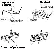
Supersonic body shapes Подпись: Expansion Gradual '' Shock Centre of pressure

Also for reasons of stowage and body capacity there are advantages in curves rather than straight lines, and in a rounded nose and tail (Fig. 12.25d). From the drag and speed point of view the nose should be sharp pointed, and often is; but there are disadvantages – the pilot’s view is bad (hence the droop-

Fig 12.24 Supersonic pressure distributions

(a) Pattern of shocks and expansions.

(b) Pressure distribution and centre of pressure.

snoot as on the Concorde), the sharp point is useless for stowage, and the transmission of radar pulses is unsatisfactory. The tail portion can be cut off, like the rear of a bullet, without much loss of efficiency; and this is necessary in any case when the jet or rocket efflux is at the rear of the body (Fig. 12.25b).

A body or fuselage of some kind is clearly necessary if the aircraft is to carry pilot, passengers, mail, or goods, and if the wings are to be thin – but are wings really necessary at supersonic speeds? Bodies can easily be designed to give lift (whatever their shape they will give lift at a small angle of attack), but cannot the thrust be used to provide the lift? In earlier chapters we talked of flying wing; why not a flying body?

Well, of course, a rocket can be nothing more nor less than a flying body – and more will be said about rockets in the next chapter – but even rockets need guidance and, within the atmosphere at least, guidance and control are best achieved by fixed and movable surfaces. There is also, so far as aeroplanes are concerned, the not unimportant point of getting back to earth.

But the reason for mentioning this problem is something quite different. One advantage in having a wing at supersonic speeds is that the presence of the wing improves the lift on the body – there is interference between wing and body, but it is useful interference; and it is mutually useful, because the body produces an upwash which improves the lift of the wing.

There are great possibilities in the exploitation of beneficial interference at supersonic speeds, and it is something which we may hear a lot more about in the future. Another example of it has already been mentioned in connection with putting a centre body at the inlet of a ramjet or jet engine. A suggestion has even been made of beneficial biplane effects, by eliminating external shock bow waves, and using the shock between the wings to good effect as in an engine intake – perhaps making the biplane the engine. Who knows?

A form of area rule is still effective in reducing shock drag at supersonic speeds, but its application is rather more complicated. Since the shock waves and Mach Tines are now oblique, instead of being at right angles to the flow, the ‘area’ which must change smoothly is not that at right angles to the line of

Подпись: ParabolicПодпись: Rounded L.E. Подпись: ParabolicSupersonic body shapes

Подпись: (b) Supersonic body shapes

Rounded

Fig 12.25 Supersonic body shapes

flight, but in planes parallel to the Mach Lines. And unfortunately the incli­nation of the Mach Lines depends on the Mach Number at which the aircraft is flying, so the shape of the aircraft can only be correct for a particular Mach Number.

Supersonic wing shapes – aerofoil sections

What then of the shape of the aerofoil section?

The proviso here is that it must be thin – or to be more correct, that it must have a low thickness/chord ratio – but apart from this it doesn’t seem to matter very much. Straight lines are as good as, or better than curved surfaces; and there is no objection to corners, even sharp corners – within reason.

A flat plate would make an excellent supersonic wing section, but would not have the necessary stiffness or strength; and the easiest way to make it a practical proposition is to thicken it somewhere in the middle, and thickness in the middle leads naturally to the double-wedge, or rhombus shape, which we have already discussed (Fig. 12.9), and which is as good as any other super­sonic aerofoil section.

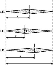
It makes little difference whether the thickest point is half-way back, or more or less; there is little change of drag for xlc ratios between 40 per cent and 60 per cent (Fig. 12.21), and the lift and centre of pressure positions are
not affected at all. But we have always got to consider flight at subsonic speeds and, from this point of view, maximum thickness should be at 40 per cent of the chord rather than farther back; from this point of view, too, it may pay to round the corners slightly.

A variation of the double-wedge is the hexagonal shape (Fig. 12.22). This gives greater depth along the chord and so greater strength, and also makes the leading edge rather less sharp, which has advantages both as regards strength and, as will be considered later, aerodynamic heating.

A bi-convex wing is also quite good (Fig. 12.23), and this is better than the others at subsonic speeds. A bi-convex wing has about the same drag as a double-wedge with maximum thickness rather outside the best range, i. e. at about 25 or 75 per cent of the chord.

Enough has been said about supersonic aerofoil sections to make it clear why the sections in Appendix 1 are all of subsonic type; there would not be much point in giving the contour of a flat plate, or even of a double-wedge – and moreover there is little difference between the lift and drag coefficients of all reasonable shapes, and still less difference in the positions of centre of pressure.

Supersonic wing shapes - aerofoil sections

Theory predicts a maximum value of LID of 12.5 for a wing with a thick – ness/chord ratio of 4 per cent at a Mach Number above about 1.3. (Note that

Fig 12.21 x/c ratio

Подпись: L.E.‘J* її = 10%

Fig 12.22 Hexagonal wing section

Подпись:L. E.

Fig 12.23 Bi-convex wing section

Supersonic wing shapes - aerofoil sections

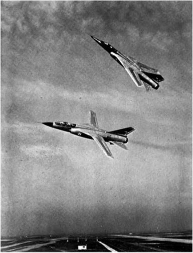
Fig 12C Variable sweep

(By courtesy of Avions Marcel Dassault, France)

The Mirage G, with wings folded and 70° sweepback, wings extended and 20° sweepback; maximum speed in level flight Mach 2.5, landing speed 110 knots; no ailerons, lateral control (wings back) by differential action of slab tail plane supplemented when wings are spread by spoilers on wings.

Fig 12D Concorde (opposite)

(By courtesy of the British Aircraft Corporation)

Supersonic wing shapes - aerofoil sections

in this statement there is no reference to the shape of the wing, or where is the greatest thickness.) This value is inferior to LID ratios for subsonic wing shapes (only about half), but it is reasonably economical when everything is taken into consideration. The lift coefficient is the same for all the shapes, and although it is smaller than those of subsonic aerofoils this does not matter at high speeds; where it does matter is that it means high stalling and landing speeds, which in turn mean long runways, and devices such as tail parachutes to help reduce the speed after landing. A leading-edge flap, or a permanent droop at the leading edge (sometimes called a droop-snoot), will appreciably lower the landing and stalling speed of a supersonic aerofoil section. As with plan shape the only way of making an aerofoil suitable for subsonic, transonic, and supersonic flight is to make it variable in shape; but in this case we know that it can be done because, in fact, it has long been done – so the only ques­tion is the best way of doing it.

Figure 12.24 shows the pressure distribution, and position of the centre of pressure, for three shapes at a small angle of attack. Comment would be super­fluous.

Supersonic wing shapes – plan form

In flight at subsonic speeds the shape of the aerofoil section is in some respects more important than the plan form of the wing, but at supersonic speeds it is the plan form which is the more important (Fig. 12B, overleaf). On the other hand, the more one studies the seemingly endless variety of both aerofoil section and plan form that are not only possible but seem to have proved suc­cessful in supersonic flight, the more one is forced to the conclusion that neither shape matters very much; supersonic flow is more accommodating than subsonic flow, less fussy in what it encounters, and although, compared with subsonic flow, the lift coefficient is less, the drag coefficient greater, and the LID ratio in consequence lower, the actual values of CL, CD, and LID, and the position of the centre of pressure seem to be little affected by the shapes of either the cross-section or the plan form of the wing.

Tet us consider first the plan form. It will be remembered that in the tran­sonic region there was advantage in a considerable degree of sweepback of the leading edge because it delayed the shock stall, the increase of drag, buffeting, and so on – in other words, it raised the critical Mach Number. It is often stated that there is no advantage in sweepback after the critical Mach Number has been passed, and that straight wings are better for supersonic flight. This might be true if the only effect of sweepback was to delay the critical Mach Number – but actually it does more than this.

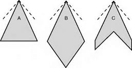
Consider, for instance, the plan shapes А, В, C, and D (Fig. 12.16, overleaf); with the possible exception of B, all these have been used on high-speed air­craft. At the apex of each are shown the Mach Tines for a Mach Number of about 1.8, and it will be noticed that the leading edges for these shapes all lie
within the Mach Cone, and this in turn means that the airflow which strikes the wing has been affected by the wing before it reaches it; if, as is probable, there are also shock waves at the nose of the aeroplane, or at the apex of the wing, the whole of the leading edge of the wing will be behind these shock waves and so will encounter an airflow of speed lower than that of the aero­plane. This airflow may not be actually subsonic, but at least the resolved part of it at right angles to the leading edge, or across the chord, is likely to be. So although a swept-back wing is better than an unswept wing in the transonic region, it may retain some of its advantages even into the supersonic region – and this applies particularly to thick wings which are naturally more prone to the formation of shock waves.
Supersonic wing shapes - plan form Supersonic wing shapes - plan form

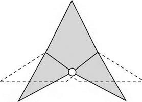
Of course, if we are to keep within the Mach Cone the sweepback must increase with the Mach Number, until eventually the delta shape may be more appropriately described as an arrow-head shape (Fig. 12.17).

Supersonic wing shapes - plan form

Fig 12.16 Supersonic wings – plan shapes

Fig 12.17 Arrow-head delta wing for high Mach Numbers

Fig 12B Supersonic configuration (opposite)

(By courtesy of British Aerospace Defence Ltd, Military Aircraft Division.) The Typhoon Eurofighter prototype with delta wing and canard foreplane for control.

FLIGHT AT SUPERSONIC SPEEDS

But whenever we discuss the advantages of sweepback we must never forget its disadvantages which are largely structural; the twisting and bending stresses on a heavily swept-back wing give many headaches to the designer and mean extra weight to provide the strength. But there is also the old bogey of tip stalling and lateral control near the stalling – and landing – speed. Shapes A and В are better structurally than C and D, they are better, too, from the point of view of tip stalling; they also have an interesting, though perhaps rather concealed, advantage in that owing to the long chord the wing can be thick (which means a good ratio of strength to weight), yet still slim as regards thickness/chord ratio (which is what matters as regards shock drag). Have C and D then no advantages? – it would be strange if they hadn’t, because they are in fact more common in practical aeroplanes than B, until recently than A also, but A is becoming increasingly popular in modern designs for supersonic transport. The advantage of C and D lies chiefly in lower drag (in spite of the point mentioned above), and so in better lift/drag ratio; they are also more suitable for the conventional fuselage and control system (if that is an advan­tage), and for engine installation.

One rather unexpected bonus resulting from the use of delta wings, or others with extreme taper and sweepback of more than 55° or so, comes from the stall itself; this is a leading edge stall which starts at the wing tip and pro­gresses gradually inboard, the separation bubble is then swept back with the leading edge and shed as a trailing vortex, tightly rolled up and with a very low pressure at its core. The low pressure acts on the forward facing parts of the upper surface of the wing giving a ‘form thrust’ (in effect a negative drag) and a lift boost; moreover the flow in the core is stable and causes little buf­feting, unlike the separation vortex on wings with sweepback of less than 50°. This is, in fact, an effective way of producing lift. Concorde used it at both subsonic and supersonic speeds. The use of fences, saw teeth and vortex gen­erators can, at best, only give partial mitigation of the resulting stalling phenomena such as the buffeting, wing drop and pitch up.

But whatever the pros and cons of sweepback there is no doubt that there is a lot to be said for the straight rectangular wing for really high supersonic speeds (Fig. 12.18). With the small aspect ratio, and tremendously high wing loading associated with such speeds, the wings are very small anyway, and from the strength point of view a rectangular wing, or a wing that is tapered for structural reasons rather than for aerodynamic reasons, will probably win the day.

Figure 12.19 shows how only small portions of a rectangular wing at super­sonic speeds (the shaded areas) can know of the existence of the tips, and these portions will tend to exhibit the normal characteristics of 3-dimensional subsonic flow, wing-tip vortices, etc., while the flow over the remainder of the wing will be straight 2-dimensional flow as if the wing was of infinite span and there were no wing tips. This leads to a rather obvious suggestion – cut off the shaded portions.

This, in fact, is sometimes evident in design, but the arguments one way and another, for sweep at leading or trailing edge (or both, or neither), for delta

Supersonic wing shapes - plan form

Fig 12.18 Wing shapes and drag

How the drag increases with Mach Number for straight, highly-swept and delta wing shapes.

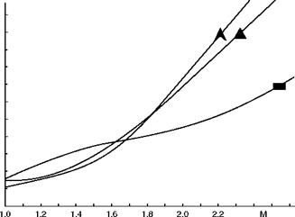
and arrow plan forms, for tail first or wing first, for tail to be larger or smaller than the wing, even to decide which is the wing and which the tail – that these arguments are endless is clearly evident from the numerous shapes and con­figurations which have been tried or suggested for missiles or supersonic aeroplanes.

The fundamental difficulty, for aircraft rather than missiles, is to provide wings that are suitable not only for supersonic flight, but also for subsonic and transonic flight. After all, supersonic aeroplanes have to take off and land; and they also have to pass through the transonic region. The real answer – so far as plan form is concerned – is surely in variable sweep (Fig. 12.20, overleaf); advocated many years ago by an eminent British inventor but, as so often

Direction of flight

Supersonic wing shapes - plan form

Fig 12.19 Rectangular wing at high Mach Numbers

Supersonic wing shapes - plan form

Fig 12.20 Variable sweep

happens, left to others to put into practice; the Americans had serious teething troubles with their first real effort in this direction, the General Dynamics swing-wing F-lll, of which so much was expected. Perhaps as a result of this disappointment, the Boeing idea of a swing-wing supersonic transport was also abandoned. Nor, in the meantime, were the French initially successful with their Mirage G (Fig. 12C, overleaf), but accumulated experience pays off and the variable sweep concept has been adopted for a number of aircraft including the Tornado.

The design process is finely balanced though; a great number of solutions to the problem of supersonic flight abound, such as the simple long-nosed delta configuration of the Anglo-French Concorde (Fig. 12D, overleaf).

Boundary layer and supersonic flow

It may be noticed that in all this we have said little or nothing about the boundary layer, and it was the boundary layer that caused all the trouble in subsonic flow when it came to corners, and it was the boundary layer that was so important in transonic flow when the incipient shock wave was formed, and for which we had to think of such devices as vortex generators.

The truth is that the boundary layer is relatively unimportant in supersonic flow; it is thin and the viscous forces within it are relatively small. This largely accounts for the ability of supersonic flow to turn sharp corners.

Curiously enough, at the even higher speeds which will be mentioned later in this chapter, the boundary layer thickens again, and once more becomes sig­nificant. So the supersonic region is especially privileged in this respect, and in many respects the theory of the flow is simpler than over any other range of speeds.

Subsonic and supersonic flow – a summary

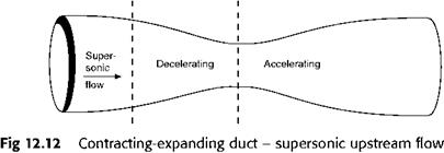
Now, I think, we are in a position to sum up the essential differences between subsonic and supersonic flow in contracting and expanding ducts, and in similar circumstances such as over aerofoils or other bodies.

In a Contracting Duct

In an Expanding Duct

Flow accelerates

Flow decelerates

Subsonic Flow

Air rarefies slightly

Air is compressed slightly

Pressure falls

Pressure rises

Flow decelerates

Flow accelerates

Supersonic Flow

Air is compressed

Air is rarefied

Pressure rises

Pressure falls

In short, everything in supersonic flow is exactly the opposite to subsonic flow with one important exception – in both cases increasing speed goes with decreasing pressure. So Bernoulli’s principle, which at low speeds is really the conservation of energy, has still some significance (though modifications are needed before it can be applied quantitatively in compressible flow).

Notice, too, that what happens in supersonic flow is what we said in an earlier chapter was what common sense might lead us to expect – a decrease of speed and compression at the throat of a venturi. It is some measure of our learning and understanding of the subject if by now this is no longer common sense!

Subsonic and supersonic flow - a summary

Expanding-contracting duct

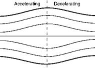
The fact that a venturi tube has an effect at supersonic speeds opposite to that at subsonic speeds leads one to wonder whether we could not get the venturi effect at supersonic speeds by having a duct shaped the opposite to that of a venturi tube, i. e. by first expanding and then contracting – and the answer, of course, is yes.

Figure 12.13 shows supersonic flow through an expanding-contracting duct.

Expanding-contracting duct

Подпись: Supersonic flow
Expanding-contracting duct

Fig 12.13 Supersonic flow through an expanding-contracting duct

Expanding-contracting duct

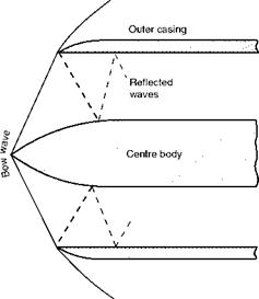
The purpose of ramjets and jet engines is to provide the thrust to propel the aero­plane or missile, and it can only do this if the velocity of outflow from the engine is greater than the velocity of the aeroplane or missile through the air. The air enters the ramjet or turbojet at the inlet where it arrives with the velocity of the aeroplane; if this is above the speed of sound we can by a clever arrangement of a centre body in the inlet (Fig. 12.14) cause shock waves to be formed here and so put up the pressure which, in the case of the turbojet, is further increased by the compressor itself. The air then speeds up in the expanding duct, and the burning of the fuel adds still further to its energy. When the gases leave the jet pipe a system of shocks and expansion wave will form in the emerging jet if the pressure is not matched to that of the atmosphere at exit, resulting in losses and consequent inefficiency.

Fig 12.14 Centre body at the inlet of a ramjet or turbine

Since the angle of the bow wave will depend on the Mach Number, the

centre body must be movable to be fully effective.

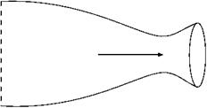
But we are not yet beaten. If we now add a divergent nozzle to the con­tracting duct (Fig. 12.15) we get at the throat an expansion wave which is reasonably gradual and, after it, a decrease of pressure more gradually to atmospheric, together with an increase of velocity – which is just what we wanted. It is in this form that the convergent-divergent nozzle is sometimes referred to as a de Laval nozzle after the famous turbine engineer of that name.