Category MECHANICS. OF FLIGHT

Control at low speeds

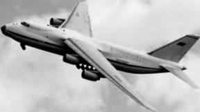
We now turn our attention to an important and interesting problem – namely, that of control at low speeds or, what amounts to the same thing, at large angles of attack. It is obviously of little use to enable a machine to fly slowly unless we can ensure that the pilot will still have adequate control over it (Fig.

9J).

Let us first state the problem by giving an example. Suppose, owing to engine failure, a pilot has to make a forced landing. If he is inexperienced – and indeed it has been known to happen to pilots of considerable experience

Control at low speeds

Fig 9) Control at low speed

The massive bulk of the Antonov AN-124 in a tight turn at low speed and low altitude. This photograph was taken from the ground!

– he will often tend to stall his aeroplane in an attempt to reach a distant field or to climb over some obstacle. Now the use of slots or flaps may postpone the stall, may help him to obtain lift at slow speeds, but they will not give him what he most needs – namely, efficient control.

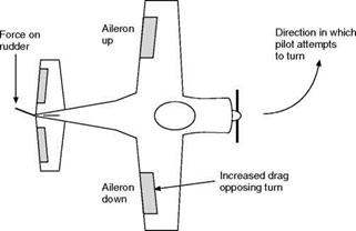
In the first place, owing to the decreased speed of the airflow over all the control surfaces, the forces acting on them will be less and they will feel ‘sloppy’. But this is not all. Suppose while he is thus flying near the stalling angle he decides that he must turn to the left, he will move the control column over to the left (which will cause the right aileron to go down and the left one to go up), at the same time applying left rudder. The rudder will make a feeble effort to turn the aeroplane to the left; but what will be the effect of the move­ment of the ailerons?

The effect of the right aileron going down should be to increase the lift on the right wing, but in practice it may decrease it, since it may increase the angle of attack beyond that angle which gives the greatest lift. But what is quite certain is that the drag will be considerably increased on the right wing, so tending to pull the aeroplane round to the right. This yawing effect, caused by the ailerons, is present at nearly all angles of attack, but it becomes particu­larly marked near the stalling angle; it is called aileron drag.

Meanwhile, what of the left wing? The lift may either have decreased or increased according to the exact angle of attack, but in any case the change in lift will be small. The drag, on the other hand, will almost certainly have decreased as the aileron moved upwards. To sum it all up, the result of the

pilot’s attempt to turn to the left is that there may or may not be a slight tend­ency to roll into the left bank required for an ordinary left-hand turn, while at the same time the drag on the wings will produce a strong tendency to turn to the right which may completely overcome the rudder’s efforts in the opposite direction (9.20). The conditions are, in fact, very favourable for a spin (both literally and metaphorically); the pilot could hardly have done better had he deliberately attempted to get the aeroplane into a spin.

So much for the problem. What solution can be found? We must endeavour to ensure that when the stalling angle is reached, or even exceeded, the move­ment of the controls by the pilot will cause the same effect on the aeroplane as in normal flight. The following improvements would all help to attain this end –

1. Increased turning effect from the rudder.

2. Down-going aileron should not increase the drag.

3. Up-going aileron should increase the drag.

4. Down-going aileron should increase the lift at all angles.

5. Up-going aileron should cause a loss of lift at all angles.

A large number of practical devices have been tried out in the attempt to satisfy these conditions; most of them have been partially successful, but none of them has solved the problem completely.

Tet us consider a few of these and see to what extent they meet our requirements.

(a) The use of very large rudders with sufficient power to overcome the yawing effect of the ailerons in the wrong direction.

The disadvantage is that the size of the rudder required to obtain the desired result is excessive for normal flight. Also this seems to be a method

Control at low speeds

of tackling the problem from the wrong standpoint – instead of curing the disease, it allows the disease to remain while endeavouring to make the patient strong enough to withstand it.

(b) A wash-out, or decrease of the angle of incidence, towards the wing tips.

This will mean that when the centre portions of the wings are at their stalling angle, the outer portions are well below the angle, and therefore the aileron will function in the normal way. The defect of this arrangement is that the wash-out must be considerable to have any appreciable effect on the control, and the result will be a corresponding loss of lift from the outer portions of the wing in normal flight. The same effect can be obtained by rigging up the ailerons so that the trailing edge of the ailerons is above the trailing edge of the wing.

(c) ‘Frise’, or other specially shaped ailerons (Fig. 9.21). This is a patented device, the idea being so to shape the aileron that when it is moved down­wards the complete top surface of the main plane and the aileron will have a smooth, uninterrupted contour causing very little drag, but when it is moved upwards the aileron, which is of the balanced variety, will project below the bottom surface of the main plane and cause excessive drag. This method has the great advantage of being simple, and it undoubtedly serves to decrease the bad yawing effect of the ailerons, and therefore it is often used. Unfortunately, its effects are not drastic enough.

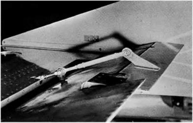
(d) Differential ailerons (Fig. 9.22). Here, again, is a delightfully simple device suffering only from the same defect that, although it provides a step in the right direction, it does not go far enough to satisfy our needs. Instead of the two ailerons moving equally up and down, a simple mechanical arrangement of the controls causes the aileron which moves upwards to move through a larger angle than the aileron which moves downwards, the idea being to increase the drag and decrease the lift on the wing with the up-going aileron, while at the same time the down-going aileron, owing to its smaller movement, will not cause excessive drag.

Control at low speeds

Control at low speeds

Подпись: Small downward movement
Control at low speeds

Large д upward movement

(e) Slot-cum-aileron control (Fig. 9.23). The slots, which need only be at the outer portions of the wings in front of the ailerons, may be of the auto­matic type, or the slot may be interconnected to the aileron in such a way that when the aileron is lowered the slot is opened, while when the aileron is raised, or in its neutral position, the slot is closed. By this means the down-going aileron will certainly serve to increase the lift for several degrees beyond the stalling angle, nor will the drag on this wing become very large since the open slot will lessen the formation of eddies. We shall therefore obtain a greater tendency to roll in the right direction and less tendency to yaw in the wrong direction. This is exactly what is required, and the system proved to be very effective in practice.

(f) Spoiler control (Fig. 9.24). Spoilers are long narrow plates normally fitted to the upper surface of the wing though they may occasionally be fitted below as well. In the ordinary way they lie flush with the surface, or even inside it, and have no effect on the performance of the aerofoil, but they can be connected to the aileron controls in such a way that when an aileron is moved up beyond a certain angle the spoiler is raised at a large angle to the airflow, or comes up through a slit, causing turbulence, decrease in lift and increase in drag. This means that the wing on which the aileron goes down gets more lift, and very little extra drag, while on the other wing the lift is ‘spoilt’ and the drag greatly increased. Thus we have a large rolling effect in the right direction combined with a yawing effect, also in the right direction – just what the doctor ordered.

Control at low speeds
This is what we aimed at, and there is the further advantage that the mechan­ical operation of the spoiler is easy, since the forces acting upon it are small. This method of control feels strange to the pilot who is unaccustomed to it because the loss of lift caused by the spoiler will result in a decided drop of that wing, which may be alarming when near the ground. But any such strangeness can soon be overcome and the pilot begins to realise the advan­tages of maintaining good lateral control, up to and beyond the normal stalling angle. The improvement in manoeuvrability is particularly noticeable

when the aeroplane approaches its ceiling. But, whatever its merits, the spoiler took a long time to become popular as a means of control, though it was, and is, used extensively as an air brake.

It is rather curious that we have been describing the use of spoilers as an aid to lateral control at low speeds; and this indeed was their original purpose, but in many types of modern aircraft it is at high speed that the aileron control may result in undesirable characteristics caused by compressibility as discussed in Chapter 11. Modern airliners use a complicated arrangement of spoilers combined with more than one set of ailerons. The control system normally automatically selects the correct combination according to flight speed.

It may be noticed that the elevator control has not been mentioned in dealing with this problem; the elevators usually remain fairly efficient, even at low speeds, since the angle of attack of the tail plane is less than that of the main planes, and therefore there is not the same tendency to stall as with the ailerons. However, on high-speed aircraft, the tail plane has to be able to com­pensate for the rearward movement of the centre of lift of the wing and it is quite common nowadays for the whole tail plane to be movable in addition to having a hinged elevator. On propeller-driven aircraft, the extra speed of the slipstream normally adds to the effectiveness of both rudder and elevators.

Before leaving the subject of control it should be mentioned that large amounts of sweepback, and even more delta-shaped wings, cause control problems of their own, but since wings of these shapes are nearly always on high-speed aircraft, their consideration will be left to a later chapter.

Mass balance

Control surfaces are often balanced in quite a different sense. A mass is fitted in front of the hinge. This is partly to provide a mechanical balancing of the mass of the control surface behind the hinge but may also be partly to help prevent an effect known as ‘flutter’ which is liable to occur at high speeds (Fig. 9.19). This flutter is a vibration which is caused by the combined effects of the changes in pressure distribution over the surface as the angle of attack is altered, and the elastic forces set up by the distortion of the structure itself. All structures are distorted when loads are applied. If the structure is elastic, as all good structures must be, it will tend to spring back as soon as the load is removed, or changes its point of application. In short, a distorted structure is like a spring that has been wound up and is ready to spring back. An aero­plane wing or fuselage can be distorted in two ways, by bending and by twisting, and each distortion can result in an independent vibration. Tike all vibrations, this flutter is liable to become dangerous if the two effects add up. The flutter may affect the control surfaces such as an aileron, or the main planes, or both. The whole problem is very complicated, but we do know of two features which help to prevent it – a stiff structure and mass balance of the control surfaces. When the old types of aerodynamic balance were used, e. g. the inset hinge or horn balance, the mass could be concealed inside the forward portion of the control surface and thus two birds were killed with one stone; but when the tap type of balance is used alone the mass must be placed on a special arm sticking out in front of the control surface. In general, however, the problems of flutter are best tackled by increasing the rigidity of the structure and control-system components.

Targe aircraft and military types now invariably have powered controls and these are much less sensitive to problems of flutter as the actuating system is very rigid.

Perhaps it should be emphasised that the mass is not simply a weight for the purpose of balancing the control surface statically, e. g. to keep the aileron floating when the control mechanism is not connected; it may have this effect, but it also serves to alter the moments of inertia of the surface, and thus alter the period of vibration and the liability to flutter. It may help to make this clear

Mass balance

Mass balance

Fig 91 Tab control mechanism (By courtesy of Piaggio, Genoa, Italy)

if we realise that mass balance is just as effective on a rudder, where the weight is not involved, as on an elevator or aileron.

On old military biplane aircraft, the exact distribution of mass on the control surfaces was so important that strict orders had to be introduced concerning the application of paint and dope to these surfaces. It is for this reason that the red, white and blue stripes which used to be painted on the rudders of Royal Air Force machines were removed (they were later restored, but only on the fixed fin), and why the circles on the wings were not allowed to overlap the ailerons. Rumour has it that when this order was first prom­ulgated, some units in their eagerness to comply with the order, but ignorant as to its purpose, painted over the circles and stripes with further coats of dope!

Tabs of this kind are called spring tabs

The final step (Figs 9.17 and 9.18, overleaf) required a little mechanical inge­nuity, but otherwise it was a natural development. The pilot was given the means of adjusting the bias while in the air, and thus he was enabled to correct any flying faults, or out-of-balance effects, as and when they occurred.

On small aircraft with manual controls these tabs may be fitted to all of the primary control surfaces. The pilot can adjust their settings from within the cockpit and can thereby arrange the trim so that the aircraft will fly ‘hands- off’ in almost any flight conditions. On aircraft with power-operated controls, such tabs are unnecessary and the trim wheels are simply used to reset the neutral or hands-off position of either the control column or the actuator system. From the pilot’s point of view this feels almost exactly like setting a trim tab.

Tabs of this kind are called spring tabs

Tabs of this kind are called spring tabs

Rigid link adjustable on ground

Tabs of this kind are called spring tabs

Tab setting adjustable by pilot in the air


Подпись: Fig 9.17Evolution of control tabs

Trim tab-control cables connected to hand

Tabs of this kind are called spring tabs


Balanced controls

Nowadays most larger aircraft have powered controls, but on smaller aircraft and older types, manual controls are still used. It is perhaps surprising to find that executive jets and even some small regional jet airliners retain manual controls. It should be remembered, however, that aircraft often remain in service for many decades, and quite recent models may only be updated vari­ants of very old designs. The following description applies to manual controls, which are the type that student pilots will initially have to deal with.

Although, in general, the forces which the pilot has to exert in order to move the controls are small, the continuous movement required in bumpy weather becomes tiring during long flights, especially when the control sur­faces are large and the speeds fairly high. For this reason controls are often balanced, or, more correctly, partially balanced (Fig. 9H).

Several methods have been employed for balancing control surfaces. Figure 9.13 shows what is perhaps the most simple kind of aerodynamic balance. The
hinge is set back so that the air striking the surface in front of the hinge causes a force which tends to make the control move over still farther; this partially balances the effect of the air which strikes the rear portion. This is effective but it must not be overdone; over-balancing is dangerous since it may remove all feel of the control from the pilot. It must be remembered that when the control surface is set a small angle, the centre of pressure on the surface is well forward of the centre of the area, and if at any angle the centre of pressure is in front of the hinge it will tend to take the control out of the pilot’s hands (or feet). Usually not more than one-fifth of the surface may be in front of the hinge.

Balanced controls

Fig 9.13 Aerodynamic balance

Balanced controls

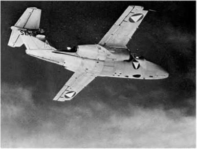
Fig 9H Balanced controls and tabs (By courtesy of SAAB, Sweden)

Twin-jet training aircraft showing the statically and aerodynamically balanced ailerons with geared servo-tabs; starboard tab adjustable for trimming. Elevators and rudder are also balanced, and there is a trim tab on the rudder, and a servo-tab (adjustable for trimming) on each elevator.

Balanced controls
Balanced controls
Balanced controls Подпись: Servo rudder

Подпись:

Balanced controls

Force on

‘RIGHT’ servo rudder

RUDDER

Fig 9.16 Servo system of balance

Figures 9.14 and 9.15 show two practical applications of this type of balance; in each some part of the surface is in front of the hinge, and each has its advantages.

Figure 9.16 shows the servo type of balance which differs in principle since the pilot in this case only moves the small extra surface (in the opposite direc­tion to normal), and, owing to the leverage, the force on the small surface helps to move the main control in the required direction. It is, in effect, a system of gearing.

Perhaps the chief interest in the servo system of balance is that it was the forerunner of the balancing tabs and trimming tabs. The development of these control tabs was very rapid and formed an interesting little bit of aviation history.

The servo system suffered from many defects, but it did show how powerful is the effect of a small surface used to deflect the air in the opposite direction to that in which it is desired to move the control surface.

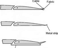
The next step was to apply this idea to an aileron when a machine was inclined to fly with one wing lower than the other. A strip of flexible metal was attached to the trailing edge of the control surface and produced the necessary corrective bias.
So far, the deflection of the air was only in one direction and so we obtained a bias on the controls rather than a balancing system. The next step gave us both balance and bias; the strip of metal became a tab, i. e. an actual flap hinged to the control surface. This tab was connected by a link to a fixed surface (the tail plane, fin or main plane), the length of this link being adjustable on the ground. When the main control surface moved in one direc­tion, the tab moved in the other and thus experienced a force which tended to help the main surface to move – hence the balance. By adjusting the link, the tab could be set to give an initial force in one direction or the other – hence the bias.

Sometimes a spring is inserted between the tab and the main control system. The spring may be used to modify the system in two possible ways –

1. So that the amount of tab movement decreases with speed, thus pre­venting the action being too violent at high speeds.

2. So that the tab does not operate at all until the main control surface has been moved through a certain angle, or until a certain control force is exerted.

Control of an aeroplane

Where an aeroplane is stable or unstable, it is necessary for the pilot to be able to control it, so that he can manoeuvre it into any desired position.

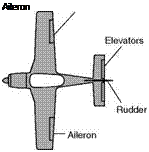
Longitudinal control is provided by the elevators, i. e. flaps hinged behind the tail plane, or movement of the whole tail plane.

Roll control is provided by the ailerons, i. e. flaps hinged at the rear of the aerofoils near each wing tip.

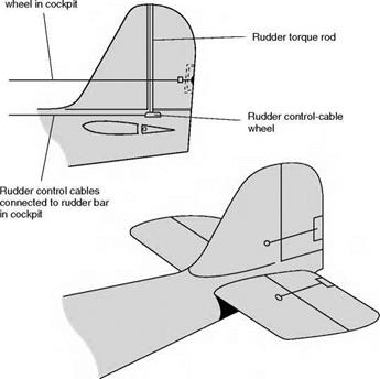
Directional control is provided by the rudder, i. e. a vertical flap hinged to the stern post.

The system of control is the same in each case, i. e. if the control surface is moved it will, in effect, alter the angle of attack and the camber of the com­plete surface, and therefore change the force upon it (see Fig. 9.12, overleaf). On many aircraft the roll can also be controlled by the use of spoilers. These are described in more detail later.
The elevators and ailerons are controlled by movements of a control column on which is mounted a handwheel which is usually abbreviated to something rather like a car steering wheel with most of the rim sawn off to leave a pair of small handgrips or ‘spectacles’.
Pushing the control column forward lowers the elevators, thus increasing the lift on the tailplane and making the nose of the aircraft drop. Turning the handwheel anti-clockwise lowers the right hand aileron and raises the left, thus rolling the aircraft left-wing down.

In old aircraft and aircraft such as fighter aircraft, where cockpit room is restricted, there is no handwheel and instead the control column moves to left and right as well as backwards and forwards – the left-hand movement is equivalent to turning the handwheel anti-clockwise (left hand down). A small version of this type of ‘joystick’ control is now used on many aircraft. It resem­bles the kind of control stick used for model aircraft and computer games. It is placed to one side of the pilot, and consequently referred to as a side-stick.

Подпись: Aileron Control of an aeroplane

Fig 9.12 Control surfaces

The use of such a small control device is possible because the flight controls are fully power operated, and require no physical force from the pilot.

The rudder is controlled by foot pedals. Pushing the left pedal forward deflects the rudder to the left and therefore turns the nose of the aircraft to the left. This can cause some problems amongst learner pilots as the movement is opposite to that of bicycle handlebars.

In each instance it will be noticed that the control surfaces are placed as far as possible away from the centre of gravity so as to provide sufficient leverage to alter the position of the aeroplane.

On modern aircraft there may also be a secondary set of inboard ailerons which are used in high speed flight where the outboard surfaces could produce excessively large rolling moments, or unacceptable structural loading or wing twist.

Lateral and directional stability

Now we are, at last, in a position to connect these two forms of stability – the sideslip essential to lateral stability will cause an air pressure on the side sur­faces which have been provided for directional stability. The effect of this pressure will be to turn the nose into the relative wind, i. e. in this case, towards the direction of sideslip. The aeroplane, therefore, will turn off its original course and in the direction of the lower wing. It is rather curious to note that the greater the directional stability the greater will be the tendency to turn off course in a sideslip. This turn will cause the raised wing, now on the outside of the turn, to travel faster than the inner or lower wing, and therefore to obtain more lift and so bank the aeroplane still further. By this time the nose of the aeroplane has probably dropped and the fat is properly in the fire with all three stabilities involved! The best way of seeing all this happen in real life is to watch a model aeroplane flying on a gusty day; the light loading and slow speed of the model make it possible to watch each step in the proceedings, whereas in the full-sized aeroplane it all happens more quickly, and also the pilot usually interferes by using his controls. If, for instance, the left wing drops and he applies rudder so as to turn the machine to the right, he will probably prevent it from departing appreciably from its course.

We can now explain the technique of turning an aeroplane. Suppose, when we want to turn to the left, instead of applying any rudder we simply bank the aeroplane to the left, as we have already seen it will slip inwards and turn to the left. That is all there is in it. So effective is this method that it is unneces­sary to use the rudder at all for turning purposes. So far as the yaw is concerned – and a turn must involve a yaw – the rudder (with the help of the fin) is still responsible, just as (with the help of the fin) it always was. The dif­ference is simply that the rudder and fin are brought into effect by the inward sideslip, instead of by application of rudder which tends to cause an outward skid. The pilot may do nothing about it, but the stability of the aeroplane puts a force on the rudder for him. It should also be emphasised that although it may be most practical, and most sensible, to commence a turn in certain air­craft without application of rudder, such a turn cannot be absolutely perfect; there must be an inward sideslip. The pilot may not notice it, the sideslip indi­cator may not detect it; but it is there just the same.

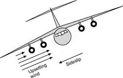
Just as a slight roll results in a sideslip and then a yawing motion so if an aircraft moves in a yawed position, as in Fig. 9.11, that is if it moves crabwise (which is really the same thing as slipping or skidding) lateral stability will come into play and cause the aircraft to roll away from the leading wing. Thus a roll causes a yaw, and a yaw causes a roll, and the study of the two cannot be separated.

If the stability characteristics of an aeroplane are such that it is very stable directionally and not very stable laterally, e. g. if it has large fin and rudder and little or no dihedral angle, or other ‘dihedral effect’, it will have a marked tend­ency to turn into a sideslip, and to bank at steeper and steeper angles, that it may get into an uncontrollable spiral – this is sometimes called spiral insta­bility, but note that it is caused by too much stability (directional).

If, on the other hand, the aeroplane is very stable laterally and not very stable directionally, it will sideslip without any marked tendency to turn into the sideslip. Such an aircraft is easily controllable by the rudder, and if the rudder only is used for a turn the aircraft will bank and make quite a nice turn.

The reader will find it interesting to think out the other characteristics which these two extremes would cause in an aeroplane, but the main point to be emphasised is that too much stability (of any type) is almost as bad as too little stability.

Directional stability

We shall first try to consider directional stability by itself, if only as a means of convincing ourselves that the two are so interlinked one with the other that

Directional stability

Fig 9.10 Effect of low-slung fuselage and engine pods on lateral stability

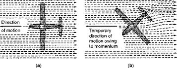
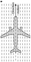
they cannot be disposed of separately. In order to establish directional stability we must ensure that, if the aeroplane is temporarily deflected from its course, it will, of its own accord, tend to return to that course again. This is almost entirely a question of the ‘side surface’ or ‘fin area’ which has already been mentioned when dealing with lateral stability, but here it is not a question of the relative height of this side surface, but whether it is in front of or behind the centre of gravity (Fig. 9F). When an aeroplane is flying in the normal way the airflow will approach it directly from the front, i. e. parallel to its longitu­dinal axis. Now imagine it to be deflected from its course as in Fig. 9.11 overleaf; owing to its momentum it will for a short time tend to continue moving in its old direction, therefore the longitudinal axis will be inclined to the airflow, and a pressure will be created on all the side surfaces on one side of the aeroplane.

If the turning effect of the pressures behind the centre of gravity is greater than the turning effect in front of the centre of gravity, the aeroplane will tend to its original course.

If, on the other hand, the turning effect in front is greater than that behind, the aeroplane will turn still farther off its course. Notice that it is the turning effect or the moment that matters, and not the actual pressure; therefore it is not merely a question of how much side surface, but also of the distance from the centre of gravity of each side surface. For instance, a small fin at the end of a long fuselage may be just as effective in producing directional stability as a large fin at the end of a short fuselage. Also, there may sometimes be more side surface in the front than in the rear, but the rear surfaces will be at a greater distance. All the side surfaces of an aeroplane, including that presented by wings with dihedral, affect the directional stability, but to the fin is allotted

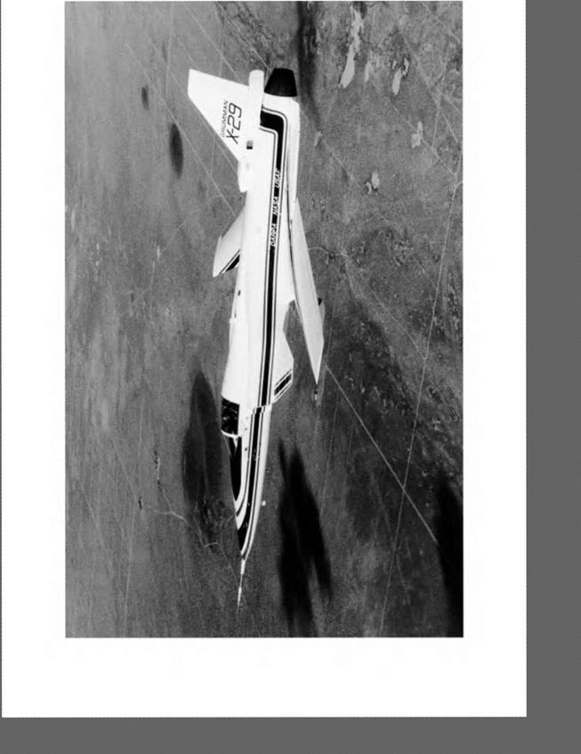
Fig 9D Sweep forward (opposite)

The Grumman X-29 research aircraft with forward-swept wings. Forward – swept wings have the same advantages in high-speed flight as swept-back wings, but give a better spanwise distribution of lift, leading to lower induced drag.

Directional stability

Directional stability

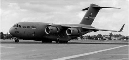
Fig 9E High fin

A massive high fin and pronounced anhedral are evident on the McDonnell Douglas C-17.

the particular task of finally adjusting matters and its area is settled accord­ingly.

There is a very close resemblance between the directional stability of an aeroplane and the action of a weathercock which always turns into the wind; in fact, one often sees a model aeroplane used as a weathercock. The simile, however, should not be carried too far, and the student must remember that there are two essential differences between an aeroplane and a weathercock – first, that an aeroplane is not only free to yaw, but also to move bodily side­ways; and secondly, that the ‘wind’, in the case of an aeroplane, is not the wind we speak of when on the ground, but the wind caused by the original motion of the aeroplane through the air. This point is emphasised because of the idea which sometimes exists that an aeroplane desires to turn head to wind. If such were the case, directional stability would be a very mixed blessing.

Correcting force on fin

Directional stability

Fig 9.11 Directional stability

(a) Before disturbance; (b) after disturbance

Directional stability

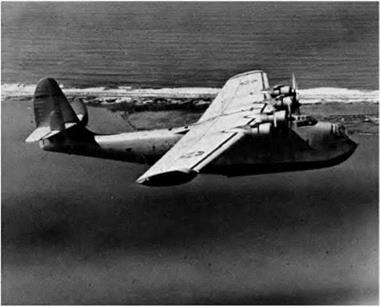
Fig 9F A classic flying boat

(By courtesy of the General Dynamics Corporation, USA)

The large side area of the hull was balanced, from the lateral stability point of view, by the dihedral on the main planes and the high fin at the rear.

Directional stability

Fig 9G Fin and directional stability

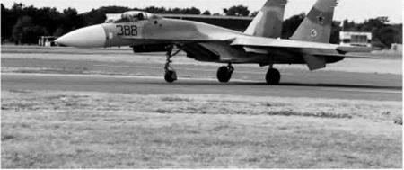
A Sukhoi Su-27 blasting down the runway with nosewheel lifting clear of the ground. Note the two large fins with dorsal extension below the tailplane. This aircraft displays exceptional manoeuvrability and control at low speed.

Fin area and lateral stability

One factor which may have considerable influence on lateral stability is the position of the various side surfaces, such as the fuselage, fin and rudder, and wheels. All these will present areas at right angles to any sideslip, so there will be pressure upon them which, if they are high above the centre of gravity, will tend to restore the aeroplane to an even keel; this applies to many modern types which have a high tail plane on top of a high fin (Figs 9.9 and 9E, later) and such types may have anhedral on the main planes to counterbalance this effect and prevent too great a degree of lateral stability; but if the side surfaces are low the pressure on them will tend to roll the aircraft over still more (Figs 9.10 and 9F, later) and so cause lateral instability, although this must be bal­anced against the effect of high wing compared with the CG position.

The reader will have noticed that, whatever the method of obtaining lateral stability, correction only takes place after a sideslip towards the low wing.

It is the sideslip that effects the directional stability.

High wing and low centre of gravity

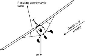
If the wings are placed in a high position and the centre of gravity is corre­spondingly low, the lateral stability can be enhanced. When an aircraft sideslips, the lift on the lower wing becomes greater than that on the higher one. Furthermore, a small sideways drag force is introduced. In consequence, the resultant force on the wing will be in the general direction indicated in Fig. 9.7. You will see that this force does not now pass through the centre of gravity so there will be a small moment which will tend to roll the aircraft back to a level condition. This will occur even on a low-wing aircraft, but is more effective with a high wing because the moment arm is greater. For this reason a high-wing aircraft requires less dihedral than a low-wing type.

High wing and low centre of gravity

Wind due to sideslip

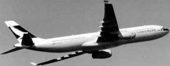
Fig 9C Sweepback

An Airbus A330 showing the sweepback of the wings.

High wing and low centre of gravityПодпись:Подпись: Direction of airflowПодпись:High wing and low centre of gravity

High wing and low centre of gravity

Higher aspect ratio and more lift on this wing

\\\\\\ o, ^ *® %\\\\\

1A і M\\\\ \\\\\^ (-,\\\\ \\\\

\\\\

\

‘ ^

4

.a

*

\\\\\u- ‘ t

\\\\4|

Direction of airflow due to sideslip

High wing and low centre of gravity

Fig 9.9 Effect of high fin on lateral stability

Sweepback and lateral stability

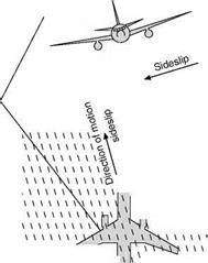
A considerable angle of sweepback (Fig. 9C) will in itself promote lateral stab­ility, for, supposing the left wing to drop, as in the two previous cases, there will be a sideslip to the left and the left-hand wing will present, in effect, a higher aspect ratio than the right wing to the correcting airflow (Fig. 9.8). It will there­fore receive more lift and, as before, recovery will take place after sideslip.

A forward sweep is sometimes used but this is not for reasons of stability (Fig. 9D, overleaf).

Dihedral angle

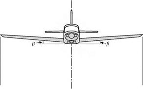
The most common method of obtaining lateral stability is by the use of a dihe­dral angle on the main planes (Figs 9.4 and 9A). Dihedral angle is taken as being the angle between each plane and the horizontal, not the total angle between the two planes, which is really the geometrical meaning of dihedral angle. If the planes are inclined upwards towards the wing tips, the dihedral is positive; if downwards, it is negative and called anhedral (Fig. 9B, overleaf); the latter arrangement is used in practice for reasons of dynamic stability.

The effect of the dihedral angle in securing lateral stability is sometimes dis­missed by saying that if one wing tip drops the horizontal equivalent on that wing is increased and therefore the lift is increased, whereas the horizontal equivalent and the lift of the wing which rises is decreased, therefore obviously the forces will tend to right the aeroplane.

Unfortunately, it is not all quite so obvious as that.

Once the aircraft has stopped rolling, and provided it is still travelling straight ahead, the aerodynamic forces will be influenced only by the airstream passing over the aircraft. This will be identical for both wings and so no restoring moment will result.

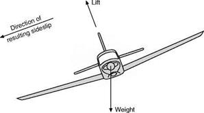
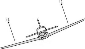
What, then, is the real explanation as to why a dihedral angle is an aid to lateral stability? When the wings are both equally inclined the resultant lift on the wings is vertically upwards and will exactly balance the weight. If, however, one wing becomes lower than the other (Fig. 9.5), then the resultant lift on the wings will be slightly inclined in the direction of the lower wing, while the weight will remain vertical. Therefore the two forces will not

Dihedral angle

130 = Dihedral angle


Fig 9.4 Lateral dihedral angle


Fig 9A Dihedral

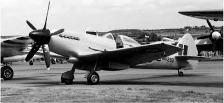
Pronounced dihedral is evident on this Spitfire: a very late post-war model.


Dihedral angleDihedral angle

balance each other and there will be a small resultant force acting in a side­ways and downwards direction. This force is temporarily unbalanced and therefore the aeroplane will move in the direction of this force – i. e. it will sideslip (Fig 9.6) – and this will cause a flow of air in the opposite direction to the slip. This has the effect of increasing the angle of attack of the lower plane and increasing that of the upper plane. The lower plane will therefore produce more lift and a restoring moment will result. Also the wing tip of the lower plane will become, as it were, the leading edge so far as the slip is concerned; and just as the centre of pressure across the chord is nearer the leading edge, so the centre of the pressure distribution along the span will now be on the lower plane; for both these reasons the lower plane will receive more lift, and after a slight slip sideways the aeroplane will roll back into its proper position. As a matter of fact, owing to the protection of the fuselage, it is probable that the flow of air created by the sideslip will not reach a large portion of the raised wing at all; this depends very much on the position of the wing relative to the fuselage.

Подпись: L
Both the leading edge effect on the lower wing, and the shielding of the upper wing by the fuselage, occur on nearly all types of aircraft, and may well mean that an aeroplane has a sufficient degree of lateral stability without any dihedral angle, or too much if some of the following effects also apply. Even if there is no actual dihedral angle on the wings, these other methods of achieving lateral stability may be described as having a ‘dihedral effect’.

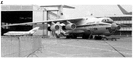
Fig 9B Anhedral

Like this Ilyushin IL-76, many aircraft with high-mounted swept wings are given a significant amount of anhedral. This is primarily used to counteract the Dutch roll tendency, a form of dynamic instability involving coupled roll and yaw motions.

Dihedral angle

Fig 9.6 The production of a sideslip