Category Model Aircraft Aerodynamics

WINGLETS AND TIP SAILS FOR MODELS

As far as model aircraft are concerned, very few tests have been performed with winglets or tip sails. They are unlikely to produce benefits unless they are properly adjusted and very few modellers have access to wind tunnels for testing purposes. If there is no restriction on the wingspan of the model, it is safer to increase aspect ratio than to use winglets unless these have been correctly designed. There are, even so, occasions when the wingspan is restricted by contest rules, or where an increase of aspect ratio (with a reduction in mean wing chord) might take the wing down to a low Reynolds number and so lose efficiency. In such cases winglets, especially of the Whitcomb type, offer some prospect of worthwhile gains.

TTie two metre sailplane class is a case in point. In 1980 tests of a model in this category were reported by Chuck Anderson (in Model Aviation, May 1980, pp. 52-5). On a wing with 25.4 cm chord, of rectangular planform, aspect ratio 7.87, winglets as shown in Figure 6.11 were fitted. These seemed to improve the performance while remaining within the two metre restriction. They also had some less desirable effects on lateral stability and control. It must also be pointed out that such additions to the tips are rather vulnerable to damage, especially in ground loops or landings which end with the model upside down.

For small free-flight models and even for F1A (A2) sailplanes, as mentioned above (6.4), wing taper is not generally desirable but the addition of winglets or sails to a rectangular wing may prove worthwhile. The Reynolds number of the mainplane would be unaffected and the tip vortex, providing the winglets were well designed, would be reduced. Anderson’s two metre sailplane, very wisely, was made with the angle of the winglets adjustable so that by repeated test flying, the best setting could be discovered.

Noel Falconer has used a refined winglet design on tailless sailplanes and electric powered models. Apart from saving drag, which is rather more severe on a swept-back wing, the winglets also serve as fins, providing very necessary lateral stability on the tailless aircraft.
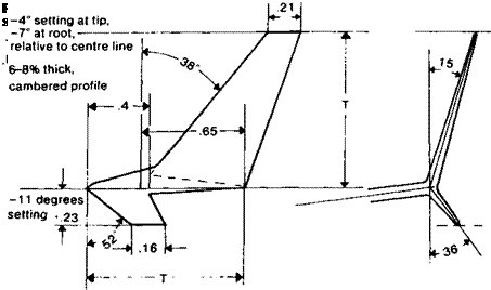
For comparison: NASA/Whitcomb winglet dimensions given as fractions of the mainplane tip chord.

Fig. 6.12

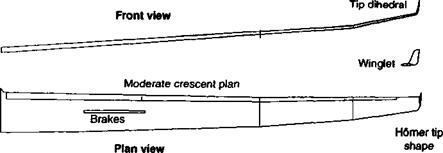
The wing of a modern full sized sailplane, using all the information gathered in recent decades about the best planform, wing tip shape and winglets (based on the Ventus 2).

DISADVANTAGES OF WINGLETS

It has been shown in Chapter 5 that the most effective method of reducing vortex drag is by increasing the aspect ratio, i. e. increasing the wing span for a given total area. It follows that whatever the gain from using winglets, a similar improvement could be achieved by an increase in aspect ratio. This could be done by fitting a simple wing extension. Such a span extension would, of course, increase the bending loads on the mainplane and would add weight, so the best solution is again decided by economics rather than aerodynamics. Nonetheless, whereas winglets require considerable research and, usually, wind tunnel testing to ensure they are of the most favourable shape and set at the best angle, to lengthen the wing is comparatively simple. Moreover, stretching a wing in this way is guaranteed to reduce vortex drag at all airspeeds. A longer wing is more prone to flutter problems and slower in roll than a short wing, but adding winglets to a short wing also increases the danger of flutter and the additional mass at the tip creates more rolling inertia.

6.18 TIP SAILS

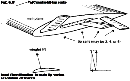
At about the same time as the Whitcomb winglets were being developed, J. J. Spillman was working on tip sails of the kind shown in Figure 6.9. These were inspired by the wing tip feathers of some large soaring birds, which are spread, finger-like, to form a series of separate wing extensions with slots between. Essentially, these are intended to work in the same way as the Whitcomb winglets, but there may be three, four or five tips ails, arranged radially and ‘en echelon’ round the tip. Each sail is adjusted to extract lift from the flow in its neighbourhood and, as with the winglet, some of this force is directed forwards, the rest

Fig. 6.10 N. A.S. A. wing sails

Подпись: г
adds bending load to the wing. The results are comparable and the same economic considerations apply. As before, an increase in aspect ratio has the same effect.

6.19 NASA TIP SAILS

Even more reminiscent of the bird wing, the NASA tip modification suggested in Figure

6.10 is intended to spread the tip vortex and reduce its strength, and this, too, reduces the vortex drag. Additional loads, as usual, must be borne by the mainplane structure and the slender tip ‘feathers’ are prone to flutter.

THE COMMERCIAL EQUATION

If an existing aeroplane is fitted with winglets, the increased bending loads compel some strengthening of the mainplane, adding weight, and there is a reduction in load carrying capacity. This may be compensated by the increased efficiency so that some fuel is saved. Clearly, whether the aircraft should or should not have winglets is finally determined not by aerodynamic considerations alone but by commercial factors such as the cost of the materials and the investment in design and the wind tunnel testing time, and the price of fuel. That the winglets do work as their inventors claim is not doubted, but this does not imply they should necessarily be fitted to every commercial aeroplane.

flight direction

WINGLETS

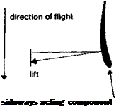
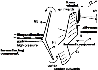
Wing tip plates of the kind just described should be distinguished from winglets and tip sails, which are different in principle. A tip plate or body is intended to restrict or prevent the tip vortex. Winglets and tip sails are designed to use the vortex by extracting some of its energy. This not only weakens the vortex but, if the energy can be turned into a force in the right direction, there is a further small gain. Winglets of the type sketched in Figure 6.8 were first developed by R. T. Whitcomb. As shown in Figure 5.1, the airflow round a wingtip is inclined outwards on the underside, upwards just beyond the tip, and inwards above. The precise angle of the flow to the direction of flight changes as the strength of the vortex varies at different angles of attack and flight speed. If an aircraft such as a commercial jet transport operates most of its time at one steady speed, it is possible to design a set of winglets which project into the vortex flow at such angles that they can, like small wings, extract some ‘lift’ force. If the winglets are set correctly this force will have a forward-acting component which can appear in the general force diagram for the whole aeroplane, as an addition to the thrust. The bulk of the winglet’s lift will, however, be directed laterally and this will not only tend to bend the winglets themselves but will increase the bending loads on the wing main structure. Since the winglets generate lift, each winglet will have a vortex at its end but this will be less intense than the main wing vortex without winglets. Some saving in drag results.

Winglets, as shown in the diagram (Figure 6.8) are cambered and twisted to meet the flow at each point at the most effective angle of attack. They are quite complicated to design and construct and are most efficient over a rather narrow range of flight speeds.

Подпись:Подпись:Подпись: P

Fig. 6.8 The Whitcomb winglet

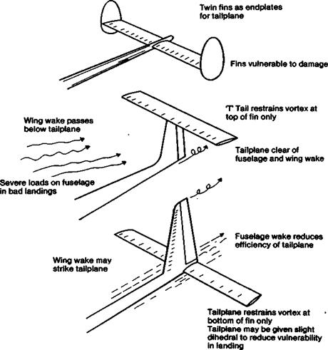
TAILPLANES AND FINS AS ENDPLATES (see Fig. 6.7, p.74)

Tip endplates can be useful to increase the effective aspect ratio of a tailplane or Tin, with possibly good effects on stability and control response. A tailplane or canard forewing fitted with end fins will have a steeper lift curve slope and become more powerful. The end fins can serve as fins for the whole model so their drag will be hardly any greater than that of a simple central fin of equal, or slightly less, area. However, the twin fins will have four tips and their aspect ratio will be very low reducing their effectiveness, and this, with their structural vulnerability, makes their use of doubtful value. They may cause more trouble than they are worth in practice. However, the tailplane itself may act as an end plate to a fin. if it is mounted on top of the fin, in ‘T configuration, or if the fin is mounted entirely above it. This restrains the vortex at one end of the fin and increases its effective aspect ratio. The T tail arrangement also carries the tailplane out of any possible airflow disturbance caused by the wing-root-to-fuselage junction. Both fin and tailplane may then be slightly reduced in area, which helps to compensate for the increase in structural weight caused by the necessity to stiffen the fin to carry extra loads. A high mounted tailplane is also less likely to blanket the fin during the towline launches or spinning. It is more vulnerable in ground loops and heavy landings but less easily damaged in normal landings because higher off the ground than a low tailplane.

Fins mounted ahead of or behind the tailplane are often preferred for their structural simplicity.

TIP PLATES AND TIP BODIES

When a wing is mounted so that it completely bridges the walls of a wind tunnel, no wing tip vortices form. The bound vortex extends from wall to wall and is cut off cleanly. The wing then behaves as if it had infinite aspect ratio and vortex-induced drag is nil. Attempts have been made many times in the past to get the benefits of an infinite aspect ratio by fitting end plates or large, streamlined tip bodies which, on some full-sized aircraft, have been used as fuel tanks. The plates or bodies are intended to act like the tunnel walls and prevent the formation of tip vortices. They do succeed in this to some extent, but to be completely successful they have to be very large. (They also steepen the slope of the lift curve.) This is not achieved without penalty. The tip plates themselves cause form and skin friction drag, and this parasitic drag in total may easily be larger than the saving. This depends very much on the Cl at which the model flies. Since at high speeds vortex drag is small in any case, while form and parasite drag are large, tip plates and bodies have a very bad effect and their use cannot be justified at all for aircraft that commonly fly faster than their speed for best L/D. (See Fig. 4.10). At lower speeds, a model with a low aspect ratio wing may be improved by fitting end plates. The best size is about twice the wing root chord in length, according to tests carried out by A. Raspet of Mississippi State College. Such plates would be a considerable nuisance on any practical model aircraft. If the wing is already of high aspect ratio, large end plates of this type will have little effect. Since the a. r. is already high, the gain in drag from the end plate is proportionately smaller, and parasite drag no less. Tip vulnerability is greater. Plates, or tip bodies, smaller than the recommended size do not inhibit the tip vortices enough to make much difference, and still add their quota of parasite drag. They should be avoided. The few full-sized aircraft and sailplanes which do have tip bodies usually do so for non-aerodynamic reasons: for example, a sailplane wing and aileron end may be protected by a small tip body such as

that of the Blanik two-seater, or the powered aircraft may lack internal space for large – capacity fuel tanks, and the wing tips may be the best place for mounting external ones.

DOWNTURNED WING TIPS

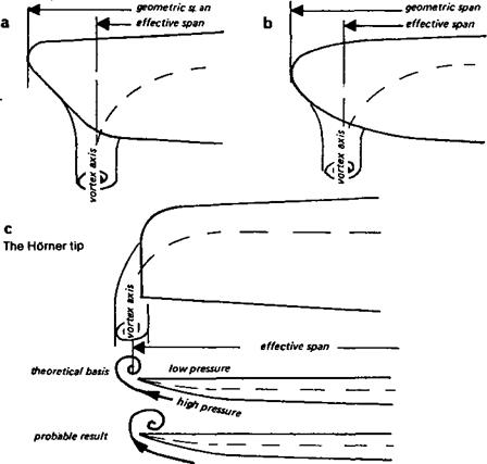
Tips that turn downwards, as shown in Fig. 6.6d, have frequently been used on sailplanes. These should not be confused with the upswept Homer tip described above. Their purpose is mainly to protect the wing tip and ailerons from damaging contact with the ground.

Aerodynamically, the downtumed tip may have some good effect, tending to confine the high pressure air and restrict its movement round to the upper side, the opposite of the Homer tip. In an exaggerated form, if the camber of the wing is carried round all the way, the result resembles the lower part of a Whitcomb winglet (Fig. 6.8). As before, there may be some benefits for aileron control and tip stalling, although little is known of this.

In the highly competitive sailplane market, fashion sometimes seems to be quite influential. There is a tendency for manufacturers and designers to introduce changes if there is even a small amount of experimental evidence to support them. The changes draw attention to their products. They stress the latest research findings, hoping thereby to make more sales to leading pilots. (These outstanding pilots usually win the competitions anyway, even when flying aircraft of slightly inferior performance.) Research goes on. Further changes, again with some scientific support, may follow after a few years. In terms of practical experience in flight, it is very difficult to show that any particular type of wing tip has a large advantage. This is the case with full sized aircraft. It is even more so with models.

TIPS FOR SLOW FLIGHT

Sailplanes and other models trimmed for flight at high angles of attack should gain something from a tip design which reduces the strength of the tip vortex or, if this can be done, compels it to form further out in the spanwise sense. Aerodynamically, the effective span of a wing is not determined merely by the geometric span. If the vortex forms somewhere inboard of the tip, which it nearly always, if not always, does, the wing loses efficiency in proportion to the inboard migration of the vortex. This is often represented by a ‘span efficiency’ figure and very few real wings are better than 95% efficient in this sense. Attempts to improve the wings of sailplanes and gliding models have tended to concentrate on devices to prevent the vortex forming inboard, thus seeking to increase the span efficiency as much as possible. It has not, however, been established that these methods succeed. Early full sized aircraft and many models have wing tip shapes which encourage premature formation of the wing tip vortex. If, for example, the tip is raked forward (Fig. 6.6a) or generously curved at the trailing edge (Fig. 6.6b), the vortex may be expected to form close to the point where the trailing edge curvature begins.

6.7 IMPROVING THE WING TIPS

Evidence from wind tunnel tests and flight tests on full sized sailplanes and some powered aircraft has been gathered over recent years to show that the airflow near the tip of a wing can be improved by adopting a generally upturned form.

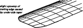
The first support for this came from the German aerodynamicist S. Horner, whose book Aerodynamic Drug was published in 1951. A development of the Horner tip was widely adopted for full sized sailplanes, as illustrated in Fig. 6.6c. The tip is essentially square but the leading edge is curved back to meet the trailing edge approximately at right angles. On the underside the wing tapers in thickness upwards to a crisp edge, rather than a rounded form. The purpose of this is to allow the high pressure air below the wing to sweep easily to the tip where its energy may serve to carry the vortex to the extreme limit of the span. In practice the full effect does not seem to occur but the extension of the trailing edge to the extremity probably does carry the vortex slightly further out than with a rounded tip.

The Hdmer tip is easy to make, quite elegant in appearance, and practical in service.

More recently, sailplanes with distinctly up curved and back swept tips have appeared, as illustrated in Fig. 6.12. These are combined with the type of wing plan shown in Fig. 6.3e. The outermost panel of the wing, usually made detachable, has a slightly increased dihedral angle which blends to a Hdmer tip, and at the trailing edge of this tip a small winglet is added (see section 6.19). Because the winglets have the effect of changing the general lift distribution, the main wing is slightly less tapered than usual. For the Schempp Hirth Ventus 2 sailplane a reduction in the minimum rate of sink of 6% has been claimed. (This amounts to a matter of 3 cm per second or 7 inches per minute.) What is probably of more importance to the model flier is that the slight additional dihedral and the smoother flow over the tips, improves the handling of the aircraft at low speeds and gives better aileron control. Tip stalling is less likely.

Not all aerodynamicists are fully convinced of the benefits and it is always difficult to distinguish gains in performance made by improved wing section design, turbulators and the introduction of new structural materials, allowing wings to be thinner and stiffer, from the wing tip effects.

TIPS ON FAST FLYING MODELS

It has already been emphasised that the vortex drag is most important for aircraft flying at high lift coefficients, i. e. at high angles of attack, slowly. It follows that little vortex drag is to be saved on high speed aircraft by modification to the wing tips. Parasite and profile

Fig. 6.7 Tail unit end plates

drag are much more important for such models and the wing tip should be designed for savings here. The plain squared off tip probably does lose something and should be rounded off in both front and plan views. There is not much else to be done.

What is more important is that the wing tips should be as simple as possible. Fancy appendages undoubtedly add parasitic drag and should be avoided. So should excrescences such as tip wheels, skids, etc.

TANDEMS AND CANARDS

If the total lift load required to support the weight of the aircraft is shared between two – main lifting surfaces disposed fore and aft, as in a true tandem layout, then as with the biplane there will be four instead of two tips and four tip vortices. As mentioned before (2.5) an aircraft which has a load-carrying tail, or forewing in the case of a canard, is in a strict sense a tandem and there will be some excess vortex drag. Only if the stabiliser is

down-turned tip as on Caproni Calif.


Fig. 6.6 Wing tip shapes


rigged to carry zero load in normal flight does the difference in pressure above and below the surface disappear. With it goes the tip vortices and the associated drag. Neither the tandem nor the canard permits this arrangement, which is achieved by appropriate positioning of the centre of gravity. (See further explanation in Chapter 12.)