Our heavyweight helicopter equal in the world does not have
In Rostov started production of the most load-lifting rotary-wing car The Russian holding «Helicopt[...]

Everything about aircrafts and helicopters. News and events in aviation worldwide. Civil, transportation, military helicopters and airplanes.

Everything about aircrafts and helicopters. News and events in aviation worldwide. Civil, transportation, military helicopters and airplanes.

Everything about aircrafts and helicopters. News and events in aviation worldwide. Civil, transportation, military helicopters and airplanes.

Everything about aircrafts and helicopters. News and events in aviation worldwide. Civil, transportation, military helicopters and airplanes.


With all tapered wings on models, the tip chord should err on the generous side to avoid tip stalling caused by scale effects and laminar separation. The aerofoil section at the tip should normally be thinner than at the root, for the same reason.
Whatever the planform of the model, serious losses occur if there are gaps through the wing at any point These often do appear in flight, particularly on large sailplanes, where the wings flex and work slightly apart at rigging joints. Through such gaps the air flows from the high to the low pressure side of the wing, creating turbulence and reducing lift Control gaps have similar effects. All such leakages should be carefully sealed.
6.6 WING TIPS
Compared with aspect ratio and the general planform and twist of the wing, wing tips are of small importance in terms of drag saving although, if a wing has a very bad tip, the resulting disturbance of airflow may cause tip stalling. In the case of a radio controlled aircraft, aileron control may be affected. In general, however, the difference in performance between a model with a good tip shape and a poorish one will be barely detectable in flight There may be something to be gained by trial and experiment, but probably not very much. Practical aircraft wings must end in tips of some kind, and wherever there is a difference of air pressure above and below a wing (or tailplane, fin, forewing etc.) a vortex will form at or near the tip. There will be a drag penalty. The greater the relative difference of pressure (i. e. the higher the Cl) the more severe the penalty will be. One of the reasons why biplanes and triplanes, and other types of multiplane, are relatively inefficient in terms of drag relative to lift is that instead of the two tip vortices of a monoplane wing, there are four, six or more.
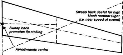
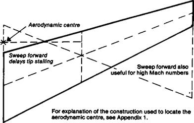
Swept wings, back or forward, are used on full-sized military and commercial aeroplanes because they are beneficial for flight approaching the speed of sound. Low speed aircraft,
|
Fig. 6.5 Swept wings
|
|
|
particularly two seat sailplanes, often use swept wings to assist with balance and cockpit і layout. The rear pilot of a sailplane like the Blanik or Ka 13 needs a view to the sides and і upwards. If the wing is straight, balance requires the rear seat to be close to the main spar of the wing and the view is then seriously restricted. Sweeping the wing forward improves the outlook (Figure 6.5). Tailless aircraft commonly have swept back wings for reasons of stability. (See Chapter 12).
Small amounts of sweep have very little effect on vortex drag. Sweep forward actually aids control at low speeds, delaying wing tip stall, but back sweep has the reverse effect і and control at low speeds may require the use of special devices such as slots, boundary layer fences, etc.
Modellers using pronounced sweep-back as, perhaps, on a scale model of a jet aircraft, ; may find similar devices essential. Sweep-back also has a slight positive dihedral effect and may be justified on aerobatic models which, in the absence of normal dihedral, may find this effect useful for steadier flight both inverted and right side up.
Sweep forward works in the opposite sense, slightly de-stabilising the model in the lateral direction.
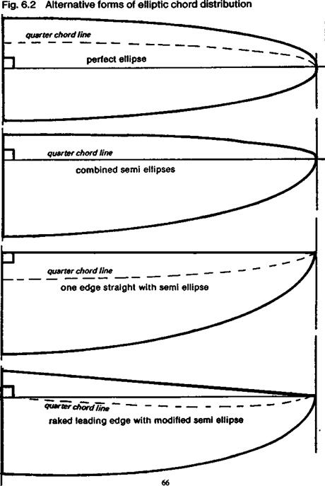
Perfectly elliptical wings are not easy either to lay out on the drawing board, or to build’ accurately. Many good compromise shapes are available and these can be made lighter, because of their simplicity, so the small aerodynamic losses may safely be ignored. Several popular examples are shown in Figure 6.3. Of these, (a) was commonly found on full-sized sailplanes during the 1920s and 1930s, and still appears on many models. If used, it might be slightly modified by employing a squared tip, as shown. The curved
|
|
|
|
|
|
|


trailing edge is not altogether easy to build. Ribs over this section of the wing cannot be made by the ‘sandwich’ method of construction. Each rib has to be plotted and cut individually. The form in Fig. 6.3b is very good from a structural point of view, giving ample root depth for spars, and can be safe If the tip chord is not reduced too far. The stall will occur first somewhere about half way out along the wing (Fig. 6. lc). This will usually cause a mild wing drop and for aerobatic models this may help to enter spins and flick rolls. The uncontrollable tip stall of the too-strongly tapered wing, however, is never desirable. Tip stalling can be avoided altogether by carefhl choice of aerofoil section, as will be discussed in Chapter 7.
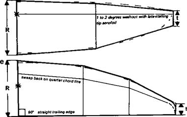
The planform (c) in Fig. 6.3 is good in all respects except that the root tends to be somewhat thin. It is easy to build and the departure from the ellipse is quite small. A convenient place for a dihedral joint is provided by the start of the tapered panel. Calculations by F. X. Wortmann suggest that if such a wing is built with three degrees of washout (i. e. reduction of incidence towards the tip), its performance is improved oveT a wide range of speeds. The washout should be progressive along the entire semi-span, rather than confined to the tapered panels only, as modellers usually do it
The planform in Fig. 6.3d is that currently preferred by most designers of full-sized sailplanes. The approximation to the ellipse is very close and the wing root is deeper than for the previous type. To build such a wing requires a little more work, but if ribs are cut by the sandwich method only one extra template is needed, for the semispan position, and it is possible to space the ribs more widely with lighter spars and covering over the outer panels, if desired, to save mass. Again, a convenient dihedral joint is provided, and on larger models the wing may be designed to part at the mid-span position for transport
It is argued by some aerodynamicists that a wing will produce a trailing vortex at every point where the trailing edge departs from a straight line. This is probably true where there is a marked change of dihedral, as on many model aircraft, or if there is a sharp break of taper. Following this argument some designers have adopted the planform shown in Figure 6.3e. The trailing edge of the wing is straight and is drawn at 90 degrees to the aircraft centre line. All the taper, still approximating the elliptical chord distribution, is on the leading edge. The result is a slightly swept back wing with respect to the quarter chord line so the aerodynamic centre of the whole wing is aft of the root quarter chord, which must be taken into account when positioning the centre of gravity.
Whether such a planform produces any detectable gain in vortex drag is hard to discover in practice.
|
Fig. 6.4 Planform to be avoided
|
6.5 BAD PLANFORMS
Some models have appeared with the planform shown in Figure 6.4. This is no doubt intended to reduce the interference drag where the wing root meets the fuselage, but the effect is wholly bad. Vortices are created which reduce the effective span and aspect ratio of the wing. The result is somewhat similar to opening a gap between wing and fuselage at the root, in effect making the monoplane wing into two separate surfaces. On some scale models of very early aeroplanes and gliders, this may be inescapable but it has drastic influence on performance.
‘Wash in’, the twisting of a wing to a higher angle of incidence at the tip, promotes tip stalling, increases the strength of the tip vortex and should be avoided. If, in order to trim a model for turning flight or to balance out torque reactions from the propeller, it is necessary to rig one wing at a different angle from the other, this should normally be done by warping one tip to a smaller angle, ‘wash out’, rather than ‘washing in’ the opposite tip.
‘Wash in’ has the same effects as drooping an aileron. Differential ailerons (see Chapter 13) are geared so as to mitigate the ill effects of this by raising (‘washing out’) the aileron on one side much more than drooping the other. Adverse aileron drag, causing an undesired yaw, is caused by the difference in vortex drag between the downgoing and the upgoing sides.
6.4 THE ELLIPTICAL WING
Mathematical analysis and experiment show that the only type of wing that will produce, at all speeds, constant down wash and a load distribution exactly matching the area is one with elliptical planform distribution (Figure 6.Id). This is not quite the same thing as saying the wing should be a perfect ellipse. It may be so, but any other form which gives a chord at each point the same as the pure ellipse will have the same effect In Figure 6.2 some of the possible variations are illustrated. The effective angle of attack everywhere is the same and the Cl max. is reached simultaneously along the entire span. This follows from the equal distribution of load, area for area, of the wing. In practice, such a simultaneous stall is rarely achieved, since the wing is usually slightly yawed or ‘one wing low’ prior to the stall, and the elliptical planform will then appear to cause tip stalling of a mild kind. Tip stalling is also encouraged by the lower Re of the outer wing. To prevent this an increase of outer chord above that of the pure ellipse is needed. The perfect load distribution is also upset to some extent by the presence of the fuselage which disturbs the flow and, with some wing positions, may reduce the load-carrying capacity of the centre section of the wing to nothing. For these reasons the ellipse is best regarded as an ideal to be approached as closely as possible, rather than the best practical wing planform. For small models the bad effects of low Re at the tip may dictate a rectangular plan, as mentioned above.
The converse of a rectangular wing is one such as that shown in Figure 6.1b, strongly tapered with tips almost pointed. This is not only very inefficient but dangerous. The strength of downwash over the various parts of such a wing is such that the local angle of attack increases towards the tips, where the area is smaller. There is an aerodynamic ‘wash-in’, the tips are over-loaded and stall first, indeed, with a wing like that sketched, they would be almost permanently stalled. The narrow outer panels are called upon to provide far more lift than their section cj max. permits, while the roots contribute little. The model would fly better if its ends were cut off altogether, squaring the tips.
6.3 WASHOUT
The strongly tapered wing does possess one advantage. Because it has a very broad and thick root, it may be very lightly built without loss of strength. For this reason some early full-sized sailplanes such as the Rhonadler of 1932 adopted this type of wing. The tip stalling problems were avoided by giving the whole wing a marked twist or wash-out to reduce die geometric angle of attack over the outer panels by approximately the amount needed to equalise the downwash across the span. This tended to distribute die load more in proportion to the area and so reduced the vortex drag. The result was an efficient wing, but at only one airspeed. At the designed speed, the whole wing was working at roughly constant aerodynamic angle of attack, but at any other speed the distribution changed. In particular, as the speed increased, the wing tips reached their local zero angle of attack quite soon as the average angle of attack of the whole wing decreased. At any higher speed than this, the outer wing panels actually operated at negative angles of attack to the local airflow, and began to ‘lift’ downwards. Although this lift force was directed down, the resolved drag component was still directed aft. Thus, not only did the tips of these highly twisted wings throw extra down loads onto the rest of the wing, but they added vortex drag. More importantly, as the speed increased, the profile drag at the tips, operating at negative angles of attack, rose rapidly. From the cockpit the wing tips could be seen to bend downwards at some quite moderate airspeed, and the penetration suffered accordingly. The same effect may be observed on many model sailplanes with too much washout Too much wing twist, introduced to cure a bad choice of planform, results in a ‘one speed’ wing. This may be exactly what is desired for an FI A (‘A2’) sailplane, but not for any type that needs to fly at varying speeds. Even for an ‘A2’, wing twist renders the model more sensitive to slight trimming errors. A small departure from the ideal airspeed causes a disproportionate rise of drag.
For reasons to do with high profile drag and premature stalling at low Reynolds numbers, calculations show that almost all the aerodynamic advantages of the tapered wing are lost on small free flight models. For this reason rectangular wings are preferred for all these. By careful use of washout, the tip vortices may be reduced in power even on such a wing, at the single trim for minimum rate of sink.
Washout often proves very useful in preventing dangerous tip stalling on all models, particularly for scale types where the wing of the prototype is strongly tapered. Washout also aids aileron control at low speeds (see Chapter 7).
6.1 PLANFORM OF WINGS
Aspect ratio is by far the most important factor in reducing vortex drag, but some model aircraft designers throw away part of the advantage gained from high a. r. by carelessness in detail. As suggested in Figure 5.2., the aerodynamic or effective span of any wing is always slightly less than the physical length of the surface, because the tip vortex leaves the wing slightly in-board of the tip. A bad choice of tip shape, or a bad planform, or a wing with too much or too little twist (variation of rigging angle from place to place), reduces the effective wing span: the wing will behave as if it were smaller in both area and aspect ratio. The factor ‘k’ in the induced drag equation will enlarge.
6.2 THE RECTANGULAR WING
The easiest type of wing to build is one with rectangular plan. All the ribs are identical and there are no awkward joints in leading or trailing edge members. Such a planform is not the best aerodynamically, the basic reason being that some parts of such a wing are underemployed, not carrying their fair share of the model’s weight.
The circulation of air and vortex strength over one part of a wing influences the direction of flow over the adjacent parts and changes the local angle of attack. With a rectangular wing the tip vortex is strong and hence the downwash near the tip large. The closer a segment lies to the tip, the more it is influenced by the vortex. The section angle of attack near the tip, and hence the section ci, is reduced and almost zero. Thus, although the wing chord is constant, the load carried by each choidwise section falls off sharply towards the tips. The wing, even with no geometric twist, works at reducing aerodynamic angles of attack over the whole outer span, with the result that the load distribution resembles that sketched in Figure 6.1a.
Assuming the wing is of constant aerofoil section throughout, the maximum possible section ci, at each point is the same. Since, however, the tips are at a lower angle of attack, , they are still well below the stalling angle when the roots reach it The rectangular wing thus has an inherently safe stalling character, the wing in the centre stalls while the tips are still lifting. There is no tendency for a tip to drop first. If the model is radio controlled, the ailerons remain effective over the outer sections even when the centre is on the verge of’ stalling. Such wings need no geometric washout, but this is at a cost in terms of effective wing loading. If some of the area were taken from the tips and distributed over the central portions of the wing, the wing as a whole would stall later, at a higher total Cl, since the total Cl is made up of the average of all the section ci’s across the span.
Fig. 6.1 Planforms and load distributions
 |
b
|
|
![]()
When a model wing is drawn out with a certain total area, it is too easily assumed that each part of it will carry a share of load which is in proportion to the area at each point This is encouraged by the simple expression (see Chapter 2) for wing loading, W/S, which implies that weight divided by total area gives a true standard of comparison between models of various types. If, however, because of bad planform, some parts of a wing are relatively idle, the rest has to take on an extra burden. This implies that while one portion of the wing is lifting very little, working at a low Cl, the other parts are at higher Cl to compensate. As the equation for induced drag shows, (CDi= (Cl2/3.142 x A) x k) increasing Cl (or cj, the section lift coefficient at a point along the span in this case) causes vortex drag to rise proportionally to the square of Cl, so the drag of the whole wing is higher. At the same time, die idle part of the wing still contributes some skin drag and profile drag. Such a bad distribution of lift is reflected in the planform correction factor, k. Noticeable losses of performance can result
From the engineering point of view, high a. r. wings are thinner and narrower at the roots, where stresses are high. There is less space in the wing for spars, fittings, servo mounts,* etc., while the long span, relative to wing area, increases the bending moments. Wing tips are more vulnerable, because more likely to hit the ground in a low turn, yet they need to be lightly built to reduce inertia in roll and yaw. During building, the long, narrow wing requires greater care, since not only are warps more likely to develop, because of the greater length, but their effect in flight is greater because of the steep lift curve slope and added sensitivity to smaller angular changes.
In spite of such problems, for all models which are expected to soar in weak upcurrents or to climb on low power, the high aspect ratio wing is essential. The inevitable penalty in terms of extra structural weight and higher wing loading is repaid, for the radio controlled sailplane, since high wing loading aids the glide at speed for penetration. For ‘duration’ models too great a weight penalty is not acceptable because of the large influence of weight on the rate of climb. Even so, if the high a. r. wing can be built down to the minimum weight required for a contest model, the performance improvement on the glide will be large providing that the Reynolds number is not too low for the aerofoil section.
Aerobatic models must not be over-sensitive in pitch, and must be quick in the roll. A high aspect ratio is most undesirable for such models, although as will be mentioned again in Chapter 13, long, narrow ailerons are superior to short, broad ones of the same area. For pylon racers and speed models, aspect ratio is relatively unimportant from the drag point of view, and as with the aerobatic type, sensitivity in pitch, especially at the turns, is undesirable since it may lead to high speed stalling and an inefficient, wavering flight caused by small over-corrections by the operator.
All considerations of tailplane design and rigging must allow for the downwash effect of the wing on the airflow at the tail. The lower the a. r. of the wing, and the shorter the fuselage, the more downwash effect there will be. As a result, the tailplane’s true angle of attack is often significantly less than the geometry of the design suggests. At the trailing edge of the wing, if the planform is roughly elliptical (see Chapter 6), the downwash angle is approximately given by the formula:
„ 18.25 x Cr
Downwash = e = —A—
where A is the aspect ratio and Cl the wing lift coefficient (i. e. not including tail areas in the calculation).
At the tail for an orthodox model layout, the tip vortices will have almost completed their ‘roll up’, so the downwash angle there will be almost doubled. For most design purposes, it is found from the approximate equation:
„ . „ 35 x Ci.
Downwash = e (t)——– A—
With a canard, the forewing is in the influence of the vortices of the mainplane, since, as has been said, the upwash effect is felt ahead of the lifting surface as well as behind. The effect is roughly half as great, i. e. the upwash at a foreplane would be about half the downwash if a tailplane were at the same distance aft of die wing aerodynamic centre as the foreplane is ahead of it
It may be seen from these rough equations that a model trimmed for a high angle of attack, such as a free-flight gliding model, may easily experience a downwash angle of 3 or 4 degrees at the tail. In setting up rigging angle on the drawing board, account must be taken of this. A tailplane set at zero degrees geometrically would, in the downwash, be operating at a distinctly negative angle of attack. In a dive, of course, Cl is much reduced and the downwash approaches zero, so a tailplane set at zero geometrically would be closer to its aerodynamic zero. Many models built with ‘lifting’ tailplanes in fact when trimmed have their tails set, relative to the true local airflow, at a negative angle of attack. The camber then being the wrong way, they create more drag than they should.
A very low a. r. wing can fly safely at a wide range of angles, is easier to trim and less critical all round. The usable range of angles of attack is wider and gusts have less influence. A very low a. r. wing tends not to reach such high values of Cl, since such a wing is, in a sense, all tips and there are very strong cross flows. But the stall is postponed, possibly even to 45 degrees. This explains why low a. r. aircraft and deltas adopt nose-up attitudes on the approach to land.
5.6 TAIL UNITS AND ASPECT RATIO
The steeper slope of the lift curve of high aspect ratio wings is significant also for tail units. Fins in particular are often very insensitive and on radio controlled models the rudder attached to a low a. r. fin also may be ineffective. Because of the low aspect ratio a large change of angle of attack is needed to bring about a moderate change of Cl, so the stabilising or control force is weak unless the fin area is considerably enlarged to compensate. The habit of designing fins for their fashionable appearance rather than for efficiency is partly to blame. A fin is a small wing and should be treated as such. Sweepback adds nothing aerodynamically other than extra drag. The higher the aspect ratio, the more sensitive the surface will be to small disturbances or control movements. Perhaps the only modellers who have always had to recognise this are the magnet-steered – sailplane enthusiasts who obtain satisfactory control with very tall and light rudders. The low aspect ratio fin may have advantages on an aerobatic model for spin recovery. In a spin, the fin may be required to provide a correcting force in conditions of very marked cross flow. The high a. r. surface might be stalled at such an angle, with disastrous results, while the comparatively insensitive low a. r. fin will be capable of stopping the rotation. The dorsal fin extension sometimes added to full-sized aircraft has a similar effect, adding some area, reducing the fin a. r., without requiring major structural alterations.
Tailplanes and foreplanes on canards too are more sensitive if they have high a. r. It is vital that the stabiliser should not stall before the main surface on an orthodox layout. The tail aspect ratio must, for safety’s sake, be somewhat lower than the wing, but within that limit should still be as high as possible. If the tail is called on to carry a proportion of the total lift in normal flight (although this is not the most efficient way to design a model), it generates vortex drag which can be reduced somewhat if its a. r. is high. With high a. r., even a ‘non-lifting’ tail is more responsive to small departures from the desired trim angle than a low a. r. surface, and can be reduced in area. The drag of a small, symmetrical – sectioned tail-plane at zero lift angle of attack is very low. The high a. r. tail also has a smaller proportion of its area in danger of being blanketed by the fuselage wake or cross flow from the fin. With canards, stalling of the rear plane before the foreplane is disastrous and leads to uncontrollable nose-up pitch. The foreplane must stall first and may therefore have a high aspect ratio.
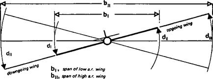
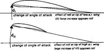
In addition high a. r. models are inherently slow in roll. This is partly because of the mass of the long wing, which opposes any force tending to inititate a roll, and, once the roll has begun, resists any force tending to stop iL More important, however, is the effect of aerodynamic damping. In a roll, the down-going wing experiences an increase in angle of attack, and the up-going wing a decrease. This applies only during the rolling movement (Figure 5.9). When the roll has settled to a steady rate, inertial resistance disappears, but the downgoing wing has a higher angle of attack and the up-going surface has a lower angle of attack. This generates lift forces opposed to the roll. To keep the roll going, a
|
|
|
Fig. 5.9 Aerodynamic damping of roll A large span wing tends to damp any rolling movement more than a short span, hence to achieve satisfactory rate of roll a high aspect ratio wing requires more effective controls |
powerful force against the aerodynamic damping must be provided, usually by ailerons. The long span of a high aspect ratio wing compels the outer panels of the wing to move through larger arcs for a given rate of roll. This creates larger damping forces. Accordingly the force to keep the roll going must be greater. Either larger ailerons are required, or they must be moved to larger angles, or other controls such as spoilers, etc., may be used to reinforce aileron effects. Many model sailplanes are controlled in roll entirely by the secondary effect of the rudder. As the aspect ratio rises this method becomes less satisfactory because the rudder is relatively ineffective in overcoming the rolling inertia and less efficient in countering wing aerodynamic damping. On the other hand, once a high a. r. wing has achieved a desired angle of bank it resists all forces tending to roll it out of the resulting turn, so such models may be steady in circling flight A further difficulty results from the increase of speed of the outer wing tip during a turn, with a corresponding slow speed on the inner wing. This causes the lift force on the tips to change in a manner tending to steepen the angle of bank. Control of man-powered aircraft with spans over 100 ft has proved very difficult partly because of this effect In full-sized sailplanes it is normally necessary to ‘hold off bank in turns, by applying aileron against the turn direction. Model sailplanes require the same type of control. To maintain a steady rate of turn in a thermal a little aileron trim against the turn may be needed.