Our heavyweight helicopter equal in the world does not have
In Rostov started production of the most load-lifting rotary-wing car The Russian holding «Helicopt[...]

Everything about aircrafts and helicopters. News and events in aviation worldwide. Civil, transportation, military helicopters and airplanes.

Everything about aircrafts and helicopters. News and events in aviation worldwide. Civil, transportation, military helicopters and airplanes.

Everything about aircrafts and helicopters. News and events in aviation worldwide. Civil, transportation, military helicopters and airplanes.

Everything about aircrafts and helicopters. News and events in aviation worldwide. Civil, transportation, military helicopters and airplanes.


There is an aerodynamic limit to the benefits of high aspect ratio, connected with scale effects as mentioned in Chapter 3, and further discussed in Chapter 7. It may be expected that if the increase of a. r. with a wing of given area results in too small a wing chord, the Reynolds number of the wing will be too low for efficient flight This can usually be prevented by careful attention to choice of aerofoil sections of such a wing. To anticipate Chapter 7, thin aerofoils are required for low Re wings, and at tips on tapered wings.
5.5 ASPECT RATIO AND TRIM SENSITIVITY
It follows directly from the effects of downwash on the angle of attack that high aspect ratio wings are inherently sensitive to changes of trim and to up and down gusts in flight The effect is compounded by what has just been said about the choice of aerofoils for operations at low Re. The thin type of profile needed for low Re turns out to be especially sensitive to slight changes of angle of attack because of the behaviour of the separation bubbles which form on the upper surfaces of such aerofoils. Quite apart from this if the variation of Cl with angle of attack is plotted on a graph for wings of various aspect ratios, as shown in Figure 5.8, it is found that the slope of the lift curve for the high aspect ratio wing is greater than that of the low a. r. surface. This follows from what has been said before; to achieve the same Cl with a low a. r. and large downwash, the geometric angle of attack must be higher. The aspect ratio has no effect on the angle at which the wing reaches Cl zero; this depends almost entirely on the wing camber. On the other hand, the maximum Cl of the high and moderate a. r. wings is the same since the occurrence of the stall depends on details of the boundary layer flow as described in Chapter 3. The high a. r. wing reaches this maximum Cl at a lower stalling angle, and as the diagram shows, the usable range of angles of attack is smaller.
A wing of infinite aspect ratio would have the greatest possible lift curve slope, as suggested by the broken line in Figure 5.8. The actual slope would depend on the aerofoil, but it can be shown that many aerofoils at high Re values, increase Ci by about. 11 for each degree increase of angle or attack, at angles below stalling. Thin aerofoils at low Re, however, have unusually steep lift curve slopes, more than 0.11 per degree, which makes the high aspect ratio models using them even more sensitive in pitch. A gust in flight may easily change the angle of attack of a slow flying model by several degrees, and if the lift curve slope is steep such a change may take the wing up to the stall or down close to zero lift
Apart from gust effects, radio controlled models with high aspect ratio, like full-sized sailplanes, are highly sensitive to elevator control. A small elevator movement can change the angle of attack of the main wing enough to cause a dramatic and sudden change of the lift forces: the lift momentarily exceeds the weight by a large margin. Violent acceleration
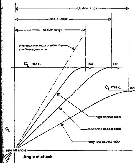
 The slope of the lift curve at different aspect ratios
results, and the inertia, or *g of the fuselage and all the concentrated items of mass in the model, oppose this. The wings deflect like archery bows and if insufficiently strong, may break. Such large deflections may also have unpredictable side effects, changing the stability and balance of the model, causing control rods in wings to bind or jam, wrinkling the covering or initiating wing flutter.
In trimming high a. r. models, small slivers of packing under the tailplane or wing have relatively large effects on the rigging angles of the narrow chord surfaces. On radio controlled models, for the same reason, sloppy control hinges, badly fitting push-rod ends, inaccurately centring servos, control rods that bend under load or expand in hot weather, all cause more trouble than they do on low a. r. models.
The aspect ratio of a wing or any other surface is found by dividing the span by the mean chord, or in cases where the mean chord is hard to determine, by dividing the square of the span by the total area, thus: A = b2/S, in the standard symbols. Among models, ‘ A-2’ sailplanes tend to the high aspect ratio side, aerobatic power models to the low. Full-sized
|
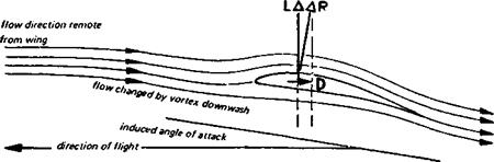
Fig. 5.6 Induced angle of attack
|
|
|
, delta winged aircraft like the Concorde have very low aspect ratio, at the other extreme ‘Open Class’ sailplanes currently average about 30 to 1, while some experimental types ; such as the British ‘Sigma’ and the Brunswick S. B. 10 exceed 36:1. With a span of 29 І metres the S. B. 10 has an average wing chord of just under 80 cm (93 ft 2 ins, 26 W ins). ; Such long, narrow and thin wings present great problems to the engineer and to the pilot, = or operator of a model. In spite of the difficulties, high aspect ratio wings are essential for |agood performances at the low speed end of the Cl scale to reduce the vortex-induced і drag.
![]()
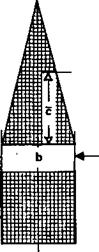
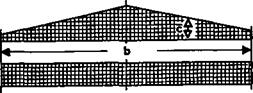 Fig. 5.7 Aspect ratio
![]()
 I,
I,
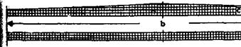
I b= span
I £» mean chord о
A«* span-i-mean chord; – s – , or span x span area; – H-
£• C w
$(
J);
Ш the wing* Ф<нт m ofeque/ ere* but of їмШу tittering aspect ratio*
|
A-36
f 5.4 VORTEX-INDUCED DRAG COEFFICIENT |
): How powerful the effects of A. R. may be can be judged from the standard formula for ^ estimation of induced drag of wing. Where CDi is the vortex-induced drag coefficient, and : A is the aspect ratio,
The factor к in this equation is a correcting figure to allow for wing planform. For a well – ; designed wing it is only a little over 1.0. It will be given more attention in the next chapter, і Otherwise, the formula shows that doubling the aspect ratio halves the vortex drag coefficient. The effect on the sinking speed of a contest glider or any gliding duration ‘ model is very large. As shown in Chapter 4, the sinking speed depends on the maximum I value of the ratio Cl’ VCd – Most of the Cd in slow flight is the vortex-induced drag
coefficient An example is worked in more detail in the appendix, where it is shown that increasing the aspect ratio of a model from 7.5 to 15 increases the power factor from about 16:1 to nearly 26:1. It is for this reason that full-sized sailplanes have such high aspect ratios. The reduction in sinking speed is vitally important for staying aloft in weak lift and also for climbing as rapidly as possible in stronger upcurrents. With a high aspect ratio sinking speeds can be very low even if the wing loading is high. High aspect ratio with high wing loading is one way of achieving a good soaring performance combined with good penetration. For absolute minimum sink, both high a. r. and low wing loading are needed, i. e., low span loading, W/b.
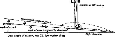
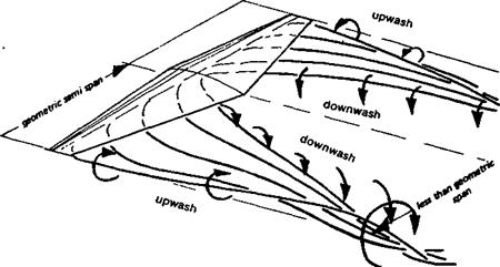
If the wing and its ‘rolled up’ vortex system is viewed from the rear, as indicated in Figure 5.4, the effect of the rotation of the vortices is to create downwash behind the wing and upwash on the outer sides. This downwash is not the same as the downwash, associated with the upwash and pressure distribution, of Fig. 2.2. That was part of the lift or bound vortex mechanism. The tip vortex downwash produces no useful lift, but it does change the general direction of flow over the wing as a whole. The streamlined flow pattern of Figure 2.2 must be considered as superimposed upon the vortex-induced downwash. The wing is at some geometric angle of attack to the undisturbed airflow remote from the wing, but near the wing the downwash effect of the trailing vortices distorts the whole flow
|
|
|
|
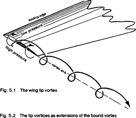
Fig. 5.3 The vortex sheet behind a real wing
|
system in proportion to the strength of the vortices (Fig. 5.5). The aerodynamic angle of attack is reduced by die vortex downwash.
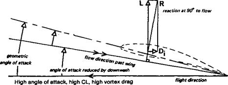
The lift force required for flight must be directed at right angles to the flight path, but the wing reaction force (neglecting profile and skin drag) is at right angles to the local airflow as changed by the downwash. The resolution of forces in Figure 5.6 shows the origin of vortex-induced drag as a component of the total reaction, directed aft The greater the geometric angle of attack, the higher the Cl at angles below stall. The higher the Cl for a given wing, the stronger the tip and other trailing vortices, and so the more downwash influence on the angle of attack and the more induced drag. The importance of vortex-induced drag for models flying at high Cl is established.
Since the cause of the downwash is the flow round the wing tips, and since this influences the rest of the wing, if there were no tips there would be no vortex drag. A wing of infinite span is impossible but a constant chord, wing-like surface, mounted across a duct in a ventilation system or in a wind tunnel, from wall to wall, generates no trailing vortices and hence no vortex drag. Practical aircraft wings must have tips, but a wing with a very large span in relation to its area, i. e., a wing of high aspect ratio, comes closer to the ideal ‘infinite’ span wing than a short, relatively broad lifting surface.
|
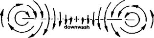
Fig. 5.4 The downwash behind a wing between the tip vortices
|
|
Fig. 5.5 Streamlined flow over a wing with tip vortices
|
5.1 THE TRAILING VORTICES
The association between induced drag and the trailing vortices behind a wing was mentioned in the closing paragraphs of Chapter 2. This will now be examined in more detail.
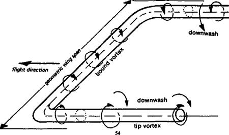
The cause of the vortices is the difference in pressure between the lower and upper surfaces of the wing when it is generating lift Near the ends of the wing the high pressure air below tends to flow outwards and round the tips towards the low pressure side. The main fore-to-aft flow stream is deflected slightly outwards on the under surface and slightly inwards above. There is also an upward component of flow outside the ends of the wing. A vortex forms behind the wing tip and trails off downstream as shown in Figure 5.1. In a simple theoretical representation, the tip vortices may be envisaged as continuations of the bound vortex of Figure 2.6. The bound vortex cannot end abruptly at the end of the wing, so it may be supposed to turn back through a right angle to form a U or horseshoe shaped vortex system as sketched in Figure 5.2.
The real picture is more complex. The cross flow at the tips influences the inner portions of the wing causing similar, though less pronounced, cross flows under and over the wing all along the span. This effect progressively weakens as distance from the tip increases, but the result is that behind the wing not a single pair, but a whole sheet of vortices forms as suggested in Fig. 5.3. Some distance behind the wing the vortex sheet rolls together into two simple vortices, the horizontal distance between them being somewhat less than the geometric wing span. The simple horseshoe vortex gives a comparable result well aft of the wing, but near the lifting surface itself a better image is of a large number of horseshoe vortices fitting one inside the other. The tip vortex at the extreme end of the wing remains the strongest, unless a very poor wing planform is chosen.
; Days with no wind at all are rare. Strictly, the effect of wind on flight is not a problem in :» aerodynamics but one of human perception, psychology and understanding. It nevertheless f seems necessary to make a brief statement since despite innumerable attempts to correct > falsehoods, the errors come up repeatedly in conversations at club level and in otherwise f reputable model magazines. Even some of those very experienced persons who set out to f teach beginners how to fly are seriously confused about this topic and perpetuate the №• misunderstandings. The true facts have been known for more than a century and have been j> amply demonstrated in practice.
: It is wise to take off and land into the wind because this reduces the speed over the ground
-i at the moment of leaving it or arriving on it. Landing or taking off downwind or across the wind produces a much longer ground run, with more chance of the aircraft swerving to one side, running out of room or striking a bump and tipping over. Once airborne this effect disappears and airspeed, not groundspeed, is what matters.
The air low down is slowed by contact and friction with the ground, producing the so – called wind gradient. Coming down through the wind gradient to land has the model passing from a fast moving airstream into one that is nearly stagnant. This can precipitate a premature stall and heavy arrival, so a little extra airspeed is advisable during die final approach, to allow for this. Climbing out after take off, the model passes from the slow moving air at ground level into the brisker flow a few metres above. This causes a surge in airspeed which may require some slight trimming action from the pilot. Above a certain level, and maintaining a more or less constant height, the wind gradient does not affect the model.
On a windy day, the air low down tends to be more turbulent so it is necessary to maintain slighdy higher airspeed when near the ground, to ensure that control is retained. This is true whether the model is flying into the wind direction, across it, or downwind when the gust strikes. At higher levels, the air is usually relatively smooth. An occasional gust can still occur but there is enough height to recover without danger.
The effect of wind on a glider attempting to make headway against it, is dealt with in Fig.
4.2 and associated text.
|
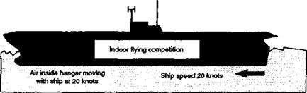
Fig. 4.12 This aircraft carrier is steaming at 20 knots. |
Inside the hangar the air is moving with the ship. An indoor flying competition is being held. The models are flying in a mass of air which is moving at 20 knots. The models behave just as they would in a steady wind of this speed. There are no strange inertia or momentum effects caused by turning this way or that. The model fliers are moving with the air so they feel no wind.
The more serious muddle concerns flight when the model is well above ground.
Despite innumerable authoritative published corrections and clarifications, there are many modellers who still believe that they should trim and control their aircraft differently when flying upwind or downwind and making turns. They do not understand that airspeed and groundspeed are two quite different things, but judge the speed of the model by its apparent motion relative to their own position. Certain types of model, and certain wing profiles, are. said to be sensitive to wind direction, models are said to surge upwards when faced into wind, and sag when flying downwind, and so on. It is even claimed sometimes that model engines run faster when the model is going against the wind and lose revolutions or overheat when they are facing the other way. This is all nonsense. The corrective actions which are sometimes recommended actually cause accidents rather than preventing them.
A wind is the movement of a huge body of air as a whole. When a model is in flight it is totally in the air and all forces and reactions on it, including inertia, kinetic energy and momentum, result from its passage through the air with no influence at all from the ground below other than gravity. The aircraft does not feel the wind passing over the ground — it is in the air and the flow over it is generated by its own airspeed. This has nothing whatever to do with the motion of the air mass itself as a whole over the ground.
Two analogies may be helpful: A balloon floats in the air and if there is any wind, moves with it. Passengers in the basket feel no wind blowing them along. If they put out a flag it hangs straight down even if flags on masts below are fluttering briskly. Tbe balloonists see the ground moving by at the speed of the wind. If one of them could launch a model aeroplane from the basket and control it from this position, it could be made to fly round and round the balloon in circles with no reference whatever to the ground. There would be none of the supposed surges and trim alterations because the pilot would be moving with the air in which the model would be flying. Flying upwind, downwind or turning in any direction, would be all the same.
Imagine flying a model aeroplane inside a large enclosed cabin, such as an empty furniture van moving on the road, or inside the enclosed hangar on an aircraft carrier at sea, or in the cabin of a huge airliner flying at 600 knots. The package of air inside the enclosed space is moving rapidly relative to the ground. The model may fly in any direction at all inside the moving air package, with no effects whatever coming from the motion of the air itself relative to the ground or sea.
The model pilot, however, is on the ground and feels the wind as a flow of air in a certain direction. From this fixed position it is easy to forget that the model is not influenced by the sensations felt on the ground. To control a model safely the pilot needs to think of the model as a thing in the air, and fly it accordingly. Pilots of full sized aircraft do this automatically for the most part and there is no reputable text book or flight instructor in full scale aviation, which confuses airspeed with groundspeed in the way modellers commonly do.
4t
In Figure 4.10 an attempt has been made to summarise in one. diagram the relative importance to different types of model of the various main types of drag. At high speeds and low lift coefficients, parasite and profile drag are dominant, vortex-induced drag is small. It follows for all models such as racers, gliders when penetrating and high powered! duration models in the climb, that design efforts should be concentrated on reducing profile and parasite drag. For slow flying models, such as soaring gliders and gliding
l
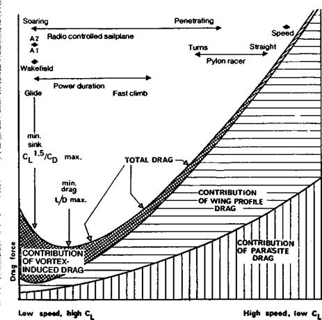
I Fig. 4.10 The drag budget
duration types, induced drag is dominant, profile drag comes a very poor second (unless by very bad choice of aerofoil, laminar separation occurs), and parasite drag is relatively unimportant. The diagram has general value, and is in many respects the key to the rest of this book. Obviously, if a racing model has been refined as far as possible with respect to profile and parasite drag, a very little further improvement will result if some attention is finally given to vortex drag reduction. Similarly, if a ‘duration’ model on the glide has vortex and profile drags cut to the minimum possible, a general ‘clean up’ of parasite drag items will bring further, but minor, improvement. The diagram gives indications as to where the main emphasis must lie. (The methods used in calculating such a drag budget for a particular model are outlined in Appendix 1.)
|
*•—– " / / u. / alt*. і • L – I |
|
/ **—– —- / / ‘olV I I L _ I |
 |
In all cases it should be noted that the wing alone is the main source of drag, either because of the vortex-induced drag at low speeds or because of aerofoil profile drag at high velocities. Parasitic drag — of tail or forewing, fuselage, interference between the various components, gaps and small protrusions — becomes important for all fast flying models but the wing is still dominant.
Fig. 4.11
A balloon moves with the air in which it flies. The people on board feel no breeze. A model aeroplane flying perfect circles in the air with the balloon basket as the centre, will maintain a steady airspeed and constant bank angle. From below, observers on the ground see the aircraft changing its apparent speed and become confused. To fly a model correctly the pilot should imagine only the airflow passing over the model.
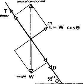
The spiral climb is effective in that it allows motors to be operated at maximum power. High rates of climb are achieved, but even better rates of climb would result if the model did not have to spiral. The speed of flight up the climb path would be greater if the excess lift force could be prevented from appearing. This can be done by reducing the angle of attack and camber of the wing, but this unfortunately spoils the gliding trim (Fig. 4.9). The best aerodynamic solution to the problem is variable trim and/or variable wing camber. By trimming the model under power to climb with a low Cl, and therefore no excess lift, energy wastage is reduced and there is no need to spiral. The wing camber should be reduced to that which gives least drag at the low lift coefficient, and the tailplane trim adjusted accordingly. When the motor run ends, both camber and trim should change mechanically to give the best possible glide. During the climb, torque and slipstream effects tending to make the model turn should be trimmed out as far as possible, to keep the flight straight
Since the climb is at low Cl and high velocity, as Figure 2.11 indicates, vortex – induced drag will be low, much lower than with the high Cl spiral climb. The parasite drag will be high, but if the correct camber is chosen, profile drag can be reduced as discussed in Chapter 7. A considerable improvement in climb results.
The rubber powered model also tends to loop under the surge of power from the motor just after release, and there is a good case for variable trim in this situation too. The
г
tailplane setting should change progressively from that for low Cl when the motor is at full power to high Cl as the power fades. (Practical mechanisms were published in the ; Aeromodeller Annual for 1972, page 78, and in A. M. Annual 1974-5, pp. 122- 127).
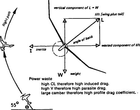
For the most efficient results in terms of rate of ascent, ways of using excess power without producing perpetual looping must be found. A model with fixed trim for minimum sink on the glide allows only one solution. Since equilibrium is impossible at full power, there must be acceleration. Looping flight is a form of acceleration, the inertia being directed outwards while the excess lift, generated by excess speed and power, is used to oppose the inertia. Instead of looping the loop, such a model must be made to turn in a spiral as it climbs. An inertia force will appear, directed outwards against the turn. The excess lift generated by the high speed will be opposed to the turning inertia by banking the wing and directing some lift force sideways. If the rate of turn is not rapid enough, excess lift will raise the model to a steeper climb angle, and rate of ascent will slow down. If the turn rate is too fast, too much lift will be directed laterally and again, the climb rate will suffer (fig. 4.8).
Although very effective, the spiral climb is wasteful of power, some of that thrust being used only to generate the sideways component of wing lift. This creates high vortex drag. Stability problems also arise.
Many models, including modem electric-powered aircraft, have much greater power available than is necessary merely for sustained flight or a slow climb. This applies to rubber driven models immediately after launching and to all successful engine driven duration models. With these, the best trim for the glide is incompatible with that for the fastest climb at maximum power.
Consider a model with a fixed trim flying straight and level under power. The tailplane holds the wing at a constant angle of attack and so at constant Cl – If the power is increased, slightly, the first result is a forward acceleration. The Cl remains the same so this increase in V causes an increase of the lift force, and this accelerates the model upwards. It begins to climb at some angle. When it settles down again to equilibrium, as was shown in Figure 1.4, the lift force is reduced because some of the weight is supported by a component of propeller thrust To get a reduced lift with fixed Cl velocity along the inclined flight path must be reduced. This is essential to balance the lift equation.
Suppose that after a flight in this condition, a little more power is added. The result will be, again after a short period of non-equilibrium, a climb at a steeper angle, but again, velocity must be reduced. The wing is still held firmly by the tailplane at its original angle of attack to the airflow, and as more and more power is applied, the wing lift force required is progressively reduced. For each power setting of the motor, there is one angle of climb, and only one, at which equilibrium can be established, and the steeper the angle, the slower the flight speed. Going to the extreme position, represented in Figure 1 Ad, it is possible to increase power until the angle of ‘climb’ is 90 degrees. The wing then must yield no lift. Since the tail is still holding the wing at its constant angle of attack, the only way the wing can give no lift is if its forward velocity is zero. For equilibrium in such an attitude, a fixed trim power model must hover with no rate of climb at all. Any forward speed would generate lift on the wing and the model would begin to loop the loop. To achieve the vertical attitude and hold it, the model requires more power than it did at some less-steep attitude. (It actually climbed quite well under reduced power, whereas now at a higher power it gains no height at all.)
Models which have only a small excess of power available for climbing, beyond that needed to sustain level flight, are necessarily trimmed to fly both under power and in the glide, at the maximum possible Cl’ VCd condition, and must be as light as possible if they are to climb at all. This also applies to many types of rubber powered model towards the end of their power run, since it is important that the climb should continue rather than the model, still under power, losing height After the power is exhausted, these models become soaring gliders, and the same design and trim requirements govern both flight modes. They may be trimmed for minimum sinking speed in the glide and this trim should be retained as far as possible for the later stages of the powered flight With a power assisted glider or an electric powered model the same rules apply.
|
Fig. 4.8 The spiral climb at high CL
|
|
Fig. 4.9 The straight climb at low CL total
|
No power waste
low CL therefore low induced drag. ,
Small camber therefore low profile drag coefficient. High velocity therefore high parasite drag.