Our heavyweight helicopter equal in the world does not have
In Rostov started production of the most load-lifting rotary-wing car The Russian holding «Helicopt[...]

Everything about aircrafts and helicopters. News and events in aviation worldwide. Civil, transportation, military helicopters and airplanes.

Everything about aircrafts and helicopters. News and events in aviation worldwide. Civil, transportation, military helicopters and airplanes.

Everything about aircrafts and helicopters. News and events in aviation worldwide. Civil, transportation, military helicopters and airplanes.

Everything about aircrafts and helicopters. News and events in aviation worldwide. Civil, transportation, military helicopters and airplanes.


Racing models need to turn efficiently at very high speeds. This is done by banking with ailerons and bringing the banked wing to a high angle of attack by applying up elevator. It is the wing lift, directed sideways, that turns the model. Too much up elevator can bring the wing to its stalling angle and precipitate a crash.
In a turn, since the wing is necessarily at a higher Cl than in level flight, wing vortex drag increases and the model loses speed. This loss is unavoidable. To attempt to turn with insufficient bank produces very high drag and even greater slowing down in a wide, skidding and yawing turn.
13.4 THE RUDDER-STEERED MODEL
Many model sailplanes, and some elementary powered models, are turned by the rudder alone with no ailerons. This, as mentioned in the previous chapter, requires the wings to be set at a dihedral angle. The yaw induced by the rudder increases the angle of attack of the wing on the side pointing into the resulting side-slip, and this wing rises. The resulting bank produces the turning force. Compared with the well executed aileron-plus-rudder turn, this control system is less efficient in that the initial yaw and slip creates some drag, but with a well trimmed model, once the turn is established little if any control deflection is needed to maintain it When the span is large, the rudder action may be somewhat slow, but providing no rapid turns are required, as may usually be the case with thermal soarers, the ‘rudder only’ control may be quite acceptable. The dihedral angle must be rather large for adequate control.
It is apparent from Figure 13.1 also that an aerobatic model with a symmetrical wing profile will hardly suffer from any adverse drag effects of aileron applications. The profile drag curve moves with the aileron, so, contrary to many statements in articles hitherto, there is no increase of profile drag caused by the downgoing aileron, and no decrease on the other side. There is, however, an increase in ci on one side and a decrease on the other. This does cause a variation of the vortex-induced drag, more lift on the rising wing creates an induced drag force tending to slow that wing down, while on the downgoing side, less lift creates less induced drag, tending to speed that wing up. A high speed model with a symmetrical profile will normally be operating at a low Cl in the first place, and induced
|
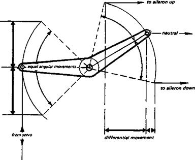
Fig. 13.3 Aileron drag
+ differential ailerons |
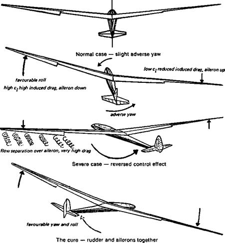
drag, as shown in Fig. 4.9, is small at high speeds and low angles of attack. It is possible to ignore the ‘adverse yaw’ effect of ailerons alone. If a slight adverse yaw is noticeable, when flying slowly, it can be corrected by use of the rudder, but for normal aerobatic flying, and on racing models, ailerons are the essential turning controls and rudder is employed mainly to counteract yaw due to slipstream effects. Exactly the same applies with full-sized, fast light aeroplanes.
At low speeds and especially on sailplanes with large span, induced drag is dominant and the adverse drag caused by ailerons is serious. As the aileron on one side moves down the local ci, already high because the model is flying slowly, rises still more, and the induced drag increases sharply on that side, tending to yaw the model against the desired direction of turn. On the other side, the ci drops, induced drag falls, which aids the adverse
yaw (Fig. 13.3). If the model is operating close to the edge of the wing profile’s low drag ‘bucket’, it is quite likely that this increase of induced drag on the upward moving wing (down-aileron side) will be supplemented by an increase of profile drag, caused by flow separation over the aileron. This will be particularly likely if the ailerons are badly designed with a clumsy hinge line, or gaps promoting flow breakaway. In extreme cases the adverse yaw caused by the ailerons may be so severe that it overcomes the rolling •effect due to the lift imbalance. The model in such a case will yaw violently away from the turn, the slow moving wing with aileron down may actually develop less lift than the fast moving one with aileron up (lift force depends on airspeed), and the turn will be the opposite of that desired by the pilot Some very early types of full-sized sailplane suffered from this effect at low speeds, while at high speeds the torsional flexibility of their wings also rendered ailerons ineffective. Only within a narrow speed range between did the ailerons work. Some model sailplanes suffer from similar troubles. On a sailplane at low speed, it is essential to use the rudder with ailerons to initiate a turn. There is an excellent case for coupling of ailerons and rudder, the adverse yaw of the ailerons being countered by simultaneous application of rudder. Modem radio control equipment makes such coupling very easy and it may be switched in or out as required, in flight
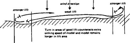
As a rule, some elevator action to control flying speed is necessary. In any turn, some of the wing lift force is directed horizontally, but the model’s weight must still be balanced by the vertical lift component (Fig. 7.8). This requires either an increase of speed or the wing must operate at a higher Cl, and hence a higher angle of attack, than in level flight Since a soaring sailplane is likely to be operating already close to the stalling angle, it is necessary to increase the flight speed in a turn to avoid a ‘wing drop’ caused by the inner wing in the turn stalling. This implies a steeper glide angle in the turn, and a higher sinking speed. The steeper the turn, the greater the loss of efficiency. In thermal soaring, since the model must turn to remain in the thermal, some penalty in performance has to be accepted. In hill soaring, the loss is small and in good or moderate conditions is hardly noticeable. However, in weak lift, the height lost on turns may be just enough to make soaring impossible. In such conditions it is common to find small patches of better ‘lift’ here and there along the slope, with weak or even nil lift between. If the turns are made in the better spots, not only is the increased sinking speed in the turn more likely to be overcome, but the model remains in the rising air longer than if it were allowed to fly straight through it The ‘beat’ worked on such a day, if possible, should thus begin and end in rising air, with straight flight between through weaker areas (Fig. 13.4). Note that all turns must be correctly banked. A flat, skidding turn creates excessive drag and increases sinking speed.
Once in the turn, a model with spiral stability will continue to turn with centralised controls until brought straight again by opposite aileron and rudder. This is a desirable
|
Fig. 13.4 Hill soaring in weak lift
|
|
|
state of affairs but may require various adjustments of dihedral angle, fin area, and gearing of rudder and ailerons, before being achieved. ‘Holding off excess bank with ailerons is usually necessary to some extent with large span aircraft
Some reduction of the adverse aileron yaw effect can be achieved by gearing the ailerons differentially. This is easily done by arranging bell cranks in the control circuit as shown in Figure 13.5 or by electronic means. The down-going movement will be less than the upward deflection, so the bulk of the rolling effect will come from the reduction of lift on the wing inside the turn. Differential ailerons cannot altogether overcome adverse yaw. The rudder is still essential for a clean turning action. Other devices, such as the Frise aileron (Fig. 13.9) or spoilers which open on one side as the aileron on that side goes up, are effective but cause increased drag and should be adopted only if all else fails.
The disadvantage of mechanical coupling of ailerons and rudder is that some special manoeuvres such as sideslips, in which the model is deliberately yawed away from the down-going wing to increase fuselage drag (so descending faster without increase of airspeed), cannot be performed. On rare occasions it may also be more difficult to enter and recover from spin, because the aileron deflection changes the stalling angle of the wing tips. In aerobatics, rolls are often accomplished by ailerons and rudder working independently.
The function of the elevator is to control the angle of attack of the wing. The wing itself may have flaps or variable camber, which can assist, oppose, or even supplant the elevator. In a well-designed model if the wing flaps are lowered, this increases the camber and simultaneously alters the geometric angle of incidence, measured from the flap trailing edge. The increase of camber causes an increase of the nose-down pitching force but, at the same time, the lift coefficient will rise, increasing downwash on the tail, tending to raise the nose. When the model settles down into a new equilibrium, it will be at a lower airspeed, but it may have only a slightly nose down or nose up attitude depending on the precise balance of flap angle, pitching moment and downwash. If, then, the elevator is
|
Fig. 13.2 The effect of hinged control surfaces
|
moved up, the airspeed will fall still further in the normal manner, but because of the greater camber with flaps down, the stall will come at a lower geometric angle of attack. Flap movement in the opposite sense has the reverse effects – q falls, the pitching moment is reduced but so is downwash. Speed rises without much change of attitude. Depression of the elevator will lead to a further increase in airspeed. Some models, particularly control line aerobatic types, have been built with elevators and flaps coupled. The advantage of this system is mainly the quick response of such a model to control movements, allowing ‘square cornered’ looping manoeuvres to be performed. The elevator must be powerful enough to overcome the adverse increased pitching moment as the flaps go down. Then the wing Cl rises very sharply and momentarily the total lift force exceeds the weight of the model, the speed not having had time to fall off. The excess lift accelerates the model in the desired direction and the elevator simultaneously rotates it into the new position. Radio controlled models find similar coupling useful.
As Figure 13.2 shows, the general effects of hinged flaps or ailerons fitted to a cambered wing are almost the same as those of a symmetrical profile similarly fitted. The only important difference is that the cambered zero flap setting has a negative zero lift or ‘absolute zero’ angle of attack. Otherwise, as before, increasing camber raises the lift curve to the left, decreasing camber moves it down to the right The drag curve shift is also as expected. The wind tunnel results given here are again at a Reynolds number too high for any models likely to employ such a cambered profile, but the general principles are not affected.
As shown in Figure 7.8 (Chapter 7) a model in a turn must bank in order that a sideways force can be produced by the wing lift, to balance the outward inertia force against the turn. Banking is accomplished normally by the action of the ailerons aided by the rudder of a model. The operation of ailerons can be understood from Fig. 7.6. As one aileron goes up, the other goes down, creating an imbalance of the lift forces on the wings, and the model rolls. The rolling movement is damped as described in Chapter 5, by the change in angle of attack on the up and down moving wings, so in a steady roll, the damping forces are exactly balanced and equalled by the imbalance caused by the ailerons. To achieve a fast rate of roll, powerful ailerons are required, together with small damping, which implies small wing span with ailerons occupying up to 80% of the trailing edge of the wing. As Figure 13.1 showed, increasing the chord of a control surface increases its effect only slightly, but extending it along the span allows it to change the camber over most of the wing, rather than only near the tips, and this is by far the best way of improving aileron control. Ailerons, however, should not be reduced in chord too far. They work in the area where the boundary layer is thick, and very narrow surfaces, or ‘strip’ ailerons suspended behind the trailing edge proper, may be blanketed and hence ineffective. It is probably best not to extend them all the way into the wing tip vortex, or completely to the wing root
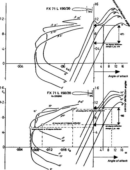
The all-moving tailplane, or ‘pendulum’ elevator, is sometimes thought to have aerodynamic advantages over the orthodox hinged elevator and fixed tailplane. Its effectiveness or sensitivity is greater for each degree of deflection. This may be established by comparing die change in ci of a symmetrical profile deflected ten degrees with that of an elevator deflected the same amount, i. e. in Figure 13.1, by comparing the lift curve of the basic profile with the curve for 10 degrees elevator. Changing the angle of attack of the symmetrical section ten degrees takes the curve up to ci about 1.1, compared with a ten degree elevator effect of about 0.5 or 0.6. However, this same ten degree angle of deflection increases the profile drag of the ‘pendulum’ elevator by more than twice, since it moves out of the ‘low drag bucket’. The hinged flap changes the camber and so shifts the drag curve favourably, for small angles of deflection. Since the pendulum elevator is more effective, it can achieve the same result by moving through a small angle. If, for example, the symmetrical profile is shifted to an angle of attack about 5 degrees, it will be as effective as a hinged flap at 10 degrees. Even this small movement takes the symmetrical profile out of the low drag range, which is quite narrow on the thin aerofoils normally used for tailplanes. However, this increase of (hag lasts only while the control is effecting a change of attitude. Once settled down in a new flight trim, as discussed in Chapter 12, the tailplane load will depend on the centre of gravity position and the static margin. Usually the load will be downwards, on a stable model. Then the hinged elevator – tailplane combination, with elevator down, is cambered the wrong way. This may take the tail out of the low drag range, whereas an all-moving, symmetrical tailplane may remain within the ‘bucket’. Better still, perhaps, an all moving tail with negative camber should produce less profile drag, on average. Such effects are small for normal aircraft since tail deflections required for trim are not large.
By careful siting of the pivot point, the symmetrical pendulum elevator may be made to throw no loads at all on the servo. Since symmetrical profiles have no pitching moment about their quarter chord point, the pivot may be sited there and the servo then has only the function of overcoming friction forces and holding the elevator in position. Full-sized sailplanes which have pendulum elevators usually have swept back tails combined with a very slight camber in order to give the pilot some aerodynamic feel in the control column. Alternatively, counter-balance tabs may be fitted. For models these are entirely superfluous and should not be imitated, except of course for exact scale types. ‘Overbalancing’ the all moving elevator, by pivoting it aft of the aerodynamic centre, is a
somewhat risky matter, though it is sometimes done. The elevator may even be used to help drive coupled flaps, reducing the combined control loads. This requires special attention to pivot bearings and push rod stiffness.
A further consideration with the all-moving tail is the difficulty of preventing gaps and aerodynamic traps where the tailplane joins the fuselage or fin. If the elevator is pivoted on the side of the fuselage or fin a gap at the root is almost inevitable. This source of parasite drag is very diflictul to seal. If a‘T’ tail is used, the all-moving tailplane may be built in one piece but then the problem of mounting it neatly on the top of the fin arises. Very few installations are as tidy, from the aerodynamic point of view, as fixed tailplane and simple hinged elevator may be. It should go without saying that the elevator hinge line on an orthodox layout should be well designed to conform with the aerofoil, and sealed against leakages from bottom surface to top or vice versa.
13.1
Like full-sized aircraft, radio controlled models rely mainly on hinged or pivoted control surfaces which alter, at the pilot’s command, the lift, drag and pitching forces to bring about a change of the aircraft’s attitude and hence its speed, rate of turn or pitch rotation, etc. The power output is controlled by the motor throttle. As the general principles of Chapter 1 and 2 show, an increase or decrease of thrust without any control surface movement will change the model’s attitude. For level flight, at different power settings, re- trimming is also required.
13.1 ELEVATORS
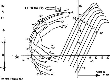
The simplest control surface is the elevator. Wind tunnel tests carried out at Stuttgart by D. Althaus on Wortmann tailplane profiles show the effect of various angular deflections of an elevator, on both the lift and drag curves, and for different sizes of hinged surface, 20% and 30% wide in terms of the chord of the whole tailplane (Fig. 13.1). The effect of a rudder on a vertical fin is of course identical. As indicated in Chapter 6, the deflection of such a surface over small angles does not change the slope of the lift curve, but moves it upwards and to the left (the elevator moving down). The c| max. increases, but the stalling angle measured geometrically decreases exactly as with a cambered aerofoil. At elevator deflections of more than 15 degrees, however, the curves show irregularities indicative of flow separation, and at the same time the drag curves show a sharp rise. As with the ordinary aerofoil section, increasing camber shifts the drag curve to higher ci positions. This is quite important since it indicates that an elevator which is trimmed to a small deflection to balance the model in flight will not necessarily generate more profile drag than when it is neutral. However, the tailplane as a whole will, in this position, probably be exerting a lifting force either upwards or downwards, and this will generate some induced drag. The wind tunnel tests also show the effect of increasing the chord of the control surface. The movement of an elevator from neutral to 10 degrees deflection with a 20% wide proportion raises Ci by approximately 0.46. Increasing the flap chord to 30% increases die effect only a very little more to about 0.47 (Fig. 13.1). The increase of control surface chord improves its effectiveness only very slightly, but the loads placed on the controlling servo motor in a model are considerably greater. The operator on the ground should be aware that any broad chord surfaces on his model are quite probably causing problems. Sometimes the control rods may bend or the model’s structure distort slightly under such loads, with the result that the actual effectiveness of the broad surface
|
|
|
is reduced. The same principles are even more valid for ailerons on both symmetrical and cambered wings: the effectiveness of the surface is increased only slighdy by broadening, but the loads on the servo are greatly magnified. If an increase of area is essential, it should if possible be achieved by increasing the spanwise extent of the hinged flap, rather than its chord. The camber of more wing surface will then be changed, with magnified effect at small cost in servo load.
The wind tunnel tests of Figure 13.1 are not, unfortunately, at low enough Re for most models. They illustrate correctly the general principles involved. They are fully valid for fast models which operate close to Re 700,000 with symmetrical or near symmetrical wing profiles. The Wortmann profiles in the 71-U-150 series (ordinates given in Appendix 3) are specifically designed for tailplanes and rudders, to give low drag when the control surface is deflected. They may be useful on aerobatic models with symmetrical wings and full-span ailerons. The aerofoils are carefully designed for use with a specific flap or elevator chord, 20,25 or 30% as indicated by the last two figures of the aerofoil designation. This should not be changed.
Somewhat analogous to the stability and balance problems of powered models are the conditions prevailing when a glider is on tow. The force of the towline creates a pitching moment which must be balanced by the tailplane, and the speed of flight on tow, especially in the early stages, is greater than normal, so the model is more sensitive. A rudder tab setting just sufficient to cause a gentle turn on the glide may cause a violent yaw on tow, which explains why ‘auto-rudders’ are needed for free flight sailplanes. If a model has stability problems on the glide, it will almost certainly behave worse under tow. As usual, a good deal of experiment and trial is needed for consistent results. A further effect to be guarded against is the distortion of wings and slender fuselages during the tow, due to the combination of extra load from the line and additional speed. A model which is perfectly satisfactory on the glide may become uncontrollable on tow if the wings twist differentially or if a slight warp is present These effects too, are mainly matters for, practical solution by means of stiffer structures and more accurate constructional methods.
Sometimes when being launched by towline or winch, a sailplane will begin to swing from side to side more or less violently and may go so far over to one side that it turns
|
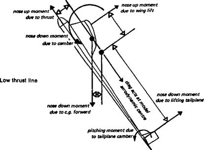
Fig. 12.20 Balance of forces on a climbing power model Moments about aerodynamic centre
|
|
|
through 180 degrees and either conies off the line or crashes heavily. The immediate solution in practice is to trim the elevator slightly down reducing the angle of attack of the mainplane. This is not possible with a free flight model, of course, but the basic cause is a wing operating at high lift coefficient. The position of the towhook too far forward may be a contributory factor.
As mentioned above, it is very difficult to achieve both spiral and weathercock lateral stability for all airspeeds and loading conditions. This tends to show up when a model is being pulled hard and fast by towline. Reducing the angle of attack changes the relationships of the wing, fin and dihedral-induced yaw and at the same time reduces the tension in the line.
Free flight sailplanes are usually towed fast and, after some time in the commonly practised ‘circular’ tow configuration while searching for lift, are pulled hard to increase airspeed then released with the line under tension, to gain some additional height This tends to send them into a stall, with loss of height, and if stability is not good, they may not recover at all. Much ingenuity has been put into designing towhooks for the circular tow. If some similar efforts were directed to elevator trim for adjusting to line tension, the problem might disappear.
Although wing tip stalling can happen on tow, it is very much less common than the side-to-side oscillation mentioned above which is not a tip-stall problem.
As mentioned before, to achieve balance in flight does not imply stability. When power is on, the stability equations also vary, generally making the model less stable because the propeller acts as a small forewing in front of the fuselage. The more power the propeller is applying to the air, the more destabilising its effects. Fortunately, this can usually be catered for by a slight increase in the static margin, but variations of torque when power is applied suddenly or reduced are less easy to trim out. In particular, when opening the throttle in order to ‘go round again’ after an aborted landing, the ailerons and rudder of a model are operating in low speed airflows and lose some effectiveness, while the sharp increase in the torque rolling force can be quite large. This is a common cause of accidents.
It is less well known that a high thrust line is more favourable for pitch stability than a low one. Hence, although the trimming arrangements will differ for the power-on and power-off conditions, because the balance of forces is different, once trimmed the high thrust line aircraft will be slightly more stable under power than when gliding.
This effect is offset to some extent by the propeller destabilising forces, but the combination of high power and low thrust line is unfavourable for stability in both respects, whereas high thrust line and propeller effects tend to cancel each other out to some extent.
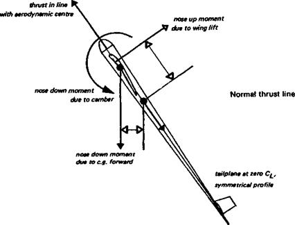
So far both stability and balance have been discussed without reference to the effects of power. In longitudinal balance, the position of the thrust line relative to the model’s aerodynamic centre is of some importance. If the thrust line is relatively high or low a pitching moment arises which must, as a rule, be balanced by the tailplane. At the same time, the slipstream over the tail changes its lifting power for a given Cl, since the velocity of flow over it is greater. In a steep climb, the weight force still acts vertically down while the lift force of the wing is at right angles to the line of flight, which changes the balance to some extent if the c. g. is fairly low relative to the aerodynamic centre. The resulting, complex force system for a typical ‘pylon’ duration power model is sketched in Fig. 12.20. The trim of such a model is highly sensitive to small changes of power. A safer arrangement, if the model has variable camber and trim, and can be made to climb straight, is sketched in the lower part of Figure 12.20. Here it is supposed that the tail is symmetrical and at zero angle of attack relative to the downwash from the mainplane. The thrust line is directed through the model’s aerodynamic centre and the c. g. also is close to the thrust line, though still ahead of the neutral point The increased velocity of the slipstream over the tailplane, at zero angle of attack, creates no increase of pitching moment from that source. The tail becomes a stabiliser. The thrust line and drag create no pitching moment The wing pitching moment is small because the camber is reduced (flaps up) during the climbing phase of flight In practice no doubt this arrangement will not be attained exactly since some compromise with the requirements of glide trim and stability will still be needed, and the pitching moment coefficient will increase when the flaps go down at the end of the power run. In general, however, the climb of such a model should be less difficult to control, especially since no steep turning is required. Note that dihedral raises the centre of drag.
The speed of the slipstream over the tail of a radio controlled model changes the effectiveness of the controls so that rudder and elevator which are sensitive when power is lull may become insufficient for control on the glide. There is little hope of real escape
|
|
|
|
|
|
|
from this difficulty, but a satisfactory compromise is usually attainable.
The fact that the slipstream rotates may cause a model to swing on take off, since the flow over the fin and rudder is at an angle. This effect is more important than the torque of the propeller, which is a force tending, in the first instance to rotate the model in roll about the propeller shaft axis, rather than to turn or yaw it A bank induced by torque, of course, will lead to a turn if uncorrected, in the air. Such a rolling tendency can, on the ground, cause a swing because unequal load is thrown onto the undercarriage, but in flight the
natural way to control torque is by a counter rolling force from the wing, either a slight twist in the appropriate direction, or by means of a trim tab of aileron. In a power model climbing straight, this will probably be essential. The slipstream effect on the rudder may be controlled by ‘side thrust’ i. e. inclining the propeller shaft slightly to the fuselage datum line. This has die advantage that the correction operates only while the power is on, and does not affect the glide trim. In full-sized practice, the rudder is trimmed at various angles to give the same effect, or the whole fin is cambered slightly to give a constant anti-yaw effect Downthrust, as already mentioned, is often valuable to adjust the thrust line for longitudinal balance, and as before, the effect disappears when the motor cuts, so the glide trim is unaffected. Radio controlled models may imitate full-sized methods by trimming the controls appropriately for various flight conditions.
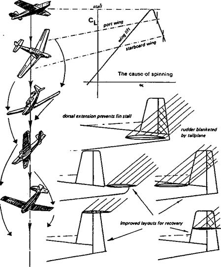
Spinning is caused by stalling of the main wing in an asymmetrical fashion as shown in Figure 12.19. In a fully developed spin, the whole wing is stalled but one side is further* beyond the stalling angle than the other, which causes that wing to drop and ‘auto – rotation’ of the model follows with a high rate of descent. To recover, the rotation must be stopped and the wing unstalled, usually requiring both elevator and fin or rudder action. Models differ widely in their spin characteristics and some cannot be made to spin at all.
![]()
small dihedral does not require complex structure
polyhedral: practical and effective
ideaі elliptical form : structure difficult
![]()
|
These are usually models with large fin areas and centre of gravity well forward. Wings with generous tip chords and washout are less likely to drop a wing when stalling, and so are less likely to enter a spin. For aerobatics, strongly tapered wings without washout and small fins promote entry to spins and a rearward c. g. will help to maintain the spin. Of course these features, if overdone, may also prevent recovery. If the c. g. is too far aft, a ‘flat spin’ may result, with no possibility of recovery.
If, during a spin, the rudder and fin are blanketed by the disturbed flow over the tailplane, recovery may be impossible. The rudder as far as possible should be mounted below the tailplane or in one of the positions suggested in Figure 12.19. A fully aerobatic model may be required to spin inverted. In this case the rudder might be disposed equally above and below the tailplane and if possible ahead of it or well behind. A low aspect ratio fin, as mentioned in Chapter 5, is desirable for spin recovery.
The position of ailerons in spinning, and in entry and recovery, will vary from model to model. In some cases entry to the spin is aided by ailerons applied against the intended direction of spin. This increases the aerodynamic angle of attack on the ‘down’ aileron side and since a cambered aerofoil reaches its stalling angle sooner (see Fig. 7.4 and 13.2) this wing may stall first and initiate the spin. In other cases, especially with broad chord wing tips, the ailerons continue to work in their normal sense even beyond the stall, in which case aileron opposed to the spin direction may prevent entry or even precipitate spinning the other way. The same applies during recovery. No general rule can be laid down, each model must be investigated and the best procedures found.
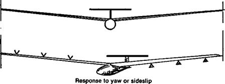
Models which rely for directional control on the rudder only, without ailerons, rely on the dihedral to turn. Insufficient dihedral may cause lack of turning power even with a large rudder. The rudder yaws the aircraft, thus causing the wing on one side to present a larger angle of attack, and the dihedral rolls the aircraft into a banked position. The total lift force of the whole wing is then tilted and this force, not the rudder, turns the aircraft. With well matched vertical tail areas and dihedral angles, the model turns quite efficiently since the brief yaw at the start is promptly countered by the roll. Once the turn is established, there should be little of no slip or skid with a suitable angle of bank. Flat, skidding turns are very inefficient
12.28 AILERONS AND DIHEDRAL
With ailerons, the amount of dihedral required for radio controlled models is quite small, and for aerobatics none at all.
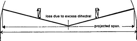
Figure 12.18 shows that too large a dihedral angle reduces the efficiency of a wing. The drag force will be no less, but because of the inclination of the wing, a component of the lift is directed horizontally. The true wing area is represented by the vertical projection in plan, rather than by the length of the wing span as the model is built on the building board. Only the minimum dihedral needed for stability should be used. For free flight models and thermal soaring R. C. gliders, it is advantageous to employ polyhedral. The steeper dihedral of the outer wing panels is more effective, due to their greater leverage arm from the model centre line. Polyhedral is a means of reducing the total dihedral of the wing compared with a straight wing model. To achieve the same effect with a straight dihedral requires a greater average dihedral angle. As with planform, an elliptical dihedral form is theoretically best, but although models have been built in this style, the gain in efficiency is very slight and there is considerable difficulty in laying out such a form on the building board. Extreme forms of dihedral should always be avoided since they promote cross flows on the wing and create vortices, increasing drag. It is also possible to have so much dihedral that turning becomes impossible.