Our heavyweight helicopter equal in the world does not have
In Rostov started production of the most load-lifting rotary-wing car The Russian holding «Helicopt[...]

Everything about aircrafts and helicopters. News and events in aviation worldwide. Civil, transportation, military helicopters and airplanes.

Everything about aircrafts and helicopters. News and events in aviation worldwide. Civil, transportation, military helicopters and airplanes.

Everything about aircrafts and helicopters. News and events in aviation worldwide. Civil, transportation, military helicopters and airplanes.

Everything about aircrafts and helicopters. News and events in aviation worldwide. Civil, transportation, military helicopters and airplanes.


Static stability refers to the stability in flight of an aircraft and has nothing to do with a model standing still. A model with positive static stability will always endeavour to hold its trimmed attitude. However, as mentioned above, some oscillation almost always occurs, the model will swing a little either way from its desired position, and will usually take a little time, and a few oscillations, to settle down. Occasionally, with a statically stable model the oscillations do not die away but continue or even become larger as time goes on. This is dynamic instability. Models with high drag, such as biplanes and most sport aircraft, have good dynamic damping and such problems rarely arise. With very ‘clean’, low drag models, especially sailplanes, gentle ‘phugoid’ oscillations are more common. The model follows a slightly wavy path; nose up, nose down, nose up, nose – down, and this wave-like motion may not be damped of its own accord. In an extreme case the up and down flight may develop into a series of stalls followed by dives and the oscillation may tend to magnify rapidly. Fortunately, the cure is found by increasing the static stability, which tends to damp the motion down as a rule. It also helps to keep the extremities of the model light so that inertia forces at the tail and extreme nose are less likely to take over.
12.13 THE NEUTRAL POINT
As described previously, every wing or wing-like surface in an airstream at a moderate angle of attack has an aerodynamic centre close to the quarter chord point. This applies to fins, tailplanes, foreplanes and such streamlined shapes as struts, wheel spats, nacelles, faired undercarriage axles, etc, etc. Even long, slender forms such as arrow shafts or fuselages have an aerodynamic centre and this is normally close to the quarter length position for moderate angles of attack.
If the structure of a model is fairly stiff, it may be treated as a fully rigid body. Then it is possible to regard the entire aircraft as one object which produces lift and drag at some fixed point equivalent to the aerodynamic centre of the whole. The exact position of this point may be found by finding the a. c. of each separate component first, then, with an allowance for the efficiency of each part as a producer of aerodynamic force (area, angle of attack, body shape etc, and whether or not in the wake of another component), the total effect of all may be added and the aerodynamic centre of the entire aircraft found. As with a wing, providing the airflow is not generally separating the centre of forces so found remains in one place at all usable flight trims.
It has already been pointed out that, for a model to be in trim, the total of all pitching moments on it, at any place on the fore and aft centre line, must be zero. Hence, when the aerodynamic centre of the aeroplane is located, if it is in trim the pitching moments of all the various components will total zero at this point
For stability, however, it is necessary that if there is a disturbance of equilibrium, causing a nose-down or a nose-up pitch, then a corrective pitching moment should appear. Then, a nose-up disturbance causing an increase of the total lift force at the aerodynamic centre of the model must automatically produce a nose-down moment, and vice versa, a nose-down upset must produce a nose-up moment.
An unstable aircraft will produce the reverse, a nose-up pitch will produce a nose-up moment, making the situation worse, and again, vice versa.
A neutrally stable aircraft, when pitched either way, will produce no pitching force either way, leaving the attitude to be determined by chance gusts and random disturbances of the air. In Figure 12.7 a symmetrical wing was shown, in trim, with zero pitching moment and the centre of gravity exactly at the aerodynamic centre of the wing. A disturbance of such a wing would produce no pitching moment either way, because symmetrical wings have no pitching moment (unless stalled). Evidently, the condition of neutral stability for an entire aircraft just described is exactly similar no corrective force arises either way if the model pitches.
If the centre of gravity of any aeroplane or glider is at the aerodynamic centre of the entire aircraft, neutral static stability is the result For this reason, the aerodynamic centre of an aeroplane is termed the neutral point Figure 12.10 shows the results if the centre of gravity is at behind or in front of the neutral point in a disturbance. In Fig. 12.10a the c. g. is at the neutral point A gust throwing the model into a climbing attitude causes an increase of the total lift force on the whole model. The c. g. and lift are still acting at the neutral point and no pitching moment results. With a nose-down upset, again, there is no corrective force.
In Figure 12.10b, the c. g. is aft of the n. p. Now a nose-up disturbance produces an increase in lift and this produces a nose-up pitching moment Vice versa for the nose-down disturbance; the lift is reduced and the nose-down pitch is worsened.
It follows that for static stability the situation of Figure 12.10c is essential. The centre
|
MOMENT APPEARS. C. Centro of gravity ahead of the neutral point STATIC STABILITY Fig. 12.10 Aerodynamic centre, neutral point, and the centre of gravity. |
 |
 |
of gravity of the aircraft must be in front of the neutral point Then a nose-up disturbance produces an increase of lift behind the c. g. and this tends to restore the normal trimmed and balanced flight attitude. A nose-down change produces a decrease of the lift aft of the c. g., and a nose-up moment arises. This applies to all model layouts, as in Figure 12.11.
In full-sized aviation, designers must consider what an aircraft will do if the pilot lets go of all the controls and allows them to float freely under the various air loads. Stick-free stability is the art of designing aircraft so that they will fly themselves, at least for some little time, without a pilot at all. In model aviation this is not of concern. The controls are normally fixed, as in free flight models, or they are held in whatever position they are placed by means of servo motors, control rods or wires. This is the case even if the pilot lets go of the radio transmitter sticks, because these are spring-loaded to centralise automatically (except for the throttle, as a rule). This is the condition known as ‘stick fixed’, although of course it does not imply that the controls do not move. On the contrary, they move, but only in response to command.
Another factor in full-sized stability calculations is ‘stick force per G’. This refers to the force which has to be exerted by the pilot on the control column, in order to produce an acceleration force of one ‘G’ (either positive or negative) on the aircraft In a loop or a turn there is always some ‘G’ force. If an aircraft has very light controls a small stick pull or push can produce a large ‘G’ force and with clumsy handling this can overstress the structure. For ordinary aeroplanes, not intended for aerobatics, stick force per ‘G’ is made large so that a pilot will have to pull very hard to produce a ‘tight’ loop, for instance, and the danger of overstressing is less. Aerobatic aircraft, flown by experts, are lighter on the controls.
With radio controlled models the stick forces felt by the pilot are those of the transmitter springs and do not relate directly to the forces felt by servos and pushrods in the model. There is, however, a similarity in that for a given stick force at the transmitter, a model with relatively small stability will respond more sharply. The same applies; clumsy handling may produce a disaster.
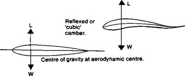
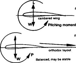
Figure 12.7 shows that a wing which has no pitching moment at any normal angle of attack may be balanced without a tail or forewing. Such a wing may be of symmetrical profile, since such aerofoils do not produce any pitching forces except when stalled, or a profile with a reflex or‘cubic’ camber line may be employed (see Figure 7.3). Figure 12.8 shows a common tailless aircraft layout which helps to overcome stability problems.
12.3 BALANCE WITH FORWARD CENTRE OF GRAVITY
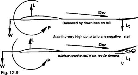
Figure 12.9 shows that balance is possible with the centre of gravity ahead of the mainplane’s aerodynamic centre, on a model of orthodox layout The tailplane and wing will generate additional vortex drag, so there is no advantage in such an arrangement except that it tends to be very stable, as will appear. Some scale model aircraft with stability problems have been flown successfully with this kind of trim.
12.4 TAILPLANE LOADS AND THE ELEVATOR POSITION
Modellers frequently are puzzled at the fact that tail loads are normally downwards in a dive or fast trim, when the elevator has to be held down to hold the attitude.
This is related closely to stability. In Figure 12.5 the tailplane is shown carrying zero load and its exact angular setting to achieve this depends on the downwash from the main wing. Suppose the pilot wishes to re-trim for a faster flight speed. The elevator (or all – moving tailplane) must first be moved down and this momentarily produces a lifting force on the tail which causes the nose to go down. But the change of wing angle of attack reduces the Cl and this in turn reduces the downwash at the tail. There is, therefore, an increase of angle of attack at the tail tending to produce a lifting force there. If the nose – down pitch brought about by the initial elevator movement is/ not quickly checked, the combined effect of down elevator and reduced downwash. will cause the nose-down motion to continue and become exaggerated. Hence as soon as the new flight attitude is reached or earlier, the elevator must be re-set for a new set of conditions. If the model is stable, it will finally be trimmed to give a download where previously it was at zero, but this condition will be reached with a small amount of down elevator at the control end.
An unstable model will react differently. The initial down elevator movement will, as before, produce a nose-down pitch, increase of flight speed, and reduced downwash, but to prevent the motion going too far, the elevator will have to be checked more quickly and the eventual trimmed position will be elevator up. That is, an unstable aircraft will dive with elevator up, and fly slowly with elevator down, even thought the initial control movements needed to bring these attitudes into being will still be in the usual sense.
A neutrally stable model will respond normally to control movements, but every flight attitude will trim out with the elevators neutral.
To achieve zero tail loads at a number of flight speeds, for the sake of reducing parasitic drag, it is possible to use an adjustable centre of gravity. This is done in some full-sized sailplanes, by means of mercury reservoirs in nose and tail. At low flight speeds when zero tail load is required with high Cl and strong downwash, the mercury is all pumped into the forward tank to bring the c. g. as far forward as possible. When high speed trim is required, and tail drag becomes more significant, an aft c. g. is required and the mercury is pumped to the tail.
Unfortunately, this reduces stability and as any radio controlled model flier knows, as the stability is reduced the elevator control becomes increasingly sensitive and even ‘twitchy’. To fly a sailplane, or any other aeroplane, at very high speeds with aft centre of gravity is very dangerous since a small twitch on the controls can precipitate a severe pitching nose up or down, and this can break the wing or tail. It is probably wiser to put up with some loss of high speed performance for the sake of safety. At low speed the gain is very slight in any case.
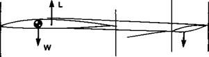
In Figure 12.6 a trim very commonly used for free-flight models is shown. The centre of gravity is located well aft, even beyond the 33% mean chord point, so that at low speeds there is an excess nose-up pitching couple of the weight and lift. To balance this, the tailplane must carry an upload and is usually cambered appropriately for this. Although this trim is almost universal on these models, it has no advantages in terms of drag saving. The tailplane produces tip vortices and the lift force generated by the tail is not enough in proportion to make this penalty worthwhile. Every attempt to prove the opposite has been proved mathematically fallacious. In contest models the fallacy is more than usually apparent because, as will appear, to provide stability with this trim requires a larger tail contribution than other trims, so there is a penalty in terms of profile drag as well as vortex drag. Every increase of tail area robs the mainplane of an equivalent amount Yet the wing is invariably more efficient than the tail, producing its lift for a smaller relative drag penalty.
|
|
|
Symmetrical profile |
|
Fig. 12.7 A symmetrical wing or one with ‘cubic’ camber, has zero pitching moment and balance is achieved with no auxiliary wing. Stability problems arise. |
|
|
|
flight trim, the tailplane will pass through a zero load point
As mentioned above, if the mainplane is of symmetrical section, the tailplane will carry no load. (A stabiliser will still be needed.) This situation can be attained at one flight speed, if the centre of gravity position is aft of the mainplane aerodynamic centre, as suggested in Figure 12.5. Here, there is a nose up moment produced by the lift and weight couple. This can be adjusted, by careful c. g. location, so that it exactly equals and so balances the
|
|
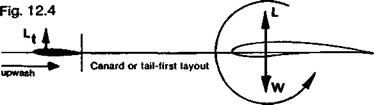
With the canard, balance is achieved with an upload on the forewing.
[L + Lt = W]. The forewing creates some vortex drag but relieves the mainplane of some load. Stability problems would arise with this arrangement. The mainplane creates upwash in the neighbourhood of the foreplane. This has an effect on rigging angles.
 |
camber-induced nose-down moment. The tail then has no balancing role in this flight attitude and is only a stabiliser.
In the days when designers thought in terms of a moving centre of pressure, it was often recommended that the centre of gravity should be located at about 33% of the mean wing chord, to produce this kind of balance. This was because the models were intended always to fly at low speeds and the wind tunnel charts (see Figure 10.4) available in those times showed that at high lift coefficients the centre of pressure on many well cambered wing sections just below the stalling angle was at about 33%. In modem terms, the effect is still the same. It happens that with well cambered profiles, tat high cj the pitching moment coefficient at the aerodynamic centre is roughly equivalent to a rearward movement of the centre of pressure of about 8%. Hence the old balance remains about right for the one, slow, flight speed. It is clear, all the same, that at any other trimmable speed, faster or slower than the one favoured for the old free-flight models, the tail load can be brought to zero only if the centre of gravity is in some other location. Putting this again in centre of pressure terms, at high speeds, as the old chart shows, the c. p. moves back, so the tail load can be made zero only by moving the centre of gravity back, to increase the strength of the lift-weight couple.
The advantage of trimming for zero tail load is that when the tailplane is not lifting, it creates no tip vortices and hence no vortex drag. With a thin, symmetrical profile its parasitic drag is then at an absolute minimum. Fortunately, at low speeds the parasitic drag contribution to the total drag of a model is quite small (see Figure 4.10) so on the free flight models such a balance was of very slight advantage. Saving a fraction of the tail drag saves only a fraction of a fraction of the parasitic drag of a model. At low speed, this itself is a small fraction of the whole. There are dangers in this trim as far as stability is concerned, but for the moment consider only the case of a dive. In a vertical dive, there is no wing lift. The weight of the model acts straight down. There is now NO pitching moment or couple of the weight with the lift to produce a nose up moment. Yet the wing camber remains and the nose down pitching force from this cause is very powerful, because the airspeed is high. The tailplane, even though originally rigged for zero load, must provide a powerful balancing down force to prevent the model bunting. It is clear again that although the zero load trim operated at slow speed, at high speeds the tail must carry a down load if balance is to be achieved.
On fast models with wings of slight camber, the zero tail load condition can be’ achieved by locating the centre of gravity aft, as before. This can result in quite substantial drag savings because parasitic drag becomes very important at high flight speeds. It still follows that the tail must produce a download at steep diving speeds, and an upload at low speeds, to maintain balance. In general, then, any model with a cambered wing profile
|
|
|
Fig. 12.6 A balanced arrangement with a lifting tailplane. As with the canard, stability problems may arise, but the tailplane relieves the wing of some load. Tailplane vortex drag increases but there is a small saving wing vortex drag [L +Lt = W] The arrangement of Figure 12.5 is superior and more stable. As before, balance in a trim of this kind can be achieved at only one speed. |
may be trimmed for zero tail load at one flight speed, but at faster speeds than this it will carry a download and at slower speeds, an upload.
With canards all the same points apply, but the load’s direction is the other way, and stability problems arise, more severely as the centre of gravity is moved aft.
In Figure 12.4 the canard layout is shown. All the same principles apply. The centre of gravity and the lift are arranged to produce no moment, but since the mainplane is cambered, the foreplane must produce a balancing upload. (This is one of the claimed advantages of the canard, but to anticipate a later paragraph the arrangement shown in Figure 12.4 would be dangerously unstable, aerodynamically. It would need ‘fly by wire’ devices to fly safely.)
Since, here, the forewing is lifting, it produces downwash which affects the angle of attack of mainplane behind it, but if the forewing is relatively small and of high aspect ratio, this is not a large effect It is worth noting all the same that whenever two or more lifting surfaces are in proximity, they do have mutual downwash effects. The forewing also lies in the vortex-induced upwash of the rear plane, which is a significant point
As with the orthodox layout, the forewing must produce the required balancing load in all trimmable conditions. In a dive, the load on the foreplane will be up, to prevent the bunt
In figures 12.3 to 9, a number of different ways of achieving trim balance are illustrated. In the most orthodox case (Fig. 12.3) the centre of gravity of the aircraft is located at the aerodynamic centre of the mainplane. (The allowance for wing sweep and planform, as always, must be made.) Since the wing in this case has some camber, there will be a nose down pitching moment, so even though the weight and lift are exactly opposed and create no pitching tendency, the tailplane must carry a download to balance out the wing’s inherent moment If the wing were truly of symmetrical section there would be no wing pitching moment and the tailplane would not need to carry any load, but the greater the camber, the greater the tail load at a given airspeed.
Since the tailplane lies behind the main wing, it will be working in the region affected by the vortex-induced downwash of the wing. This may be several degrees, depending on the wing’s planform and the wing lift coefficient, Cl, at which the model is trimmed to fly. Since Cl is high at low flight speeds, the downwash may be several degrees. (See the approximate formula in para 5.10). If the model is trimmed for fast flight, Cl will be lower and there will be less downwash. But in every case the tail must be set at just the angle required, relative to the airflow in its location, to provide exactly the downforce needed to bring the total of all the pitching moments to zero.
![]()
 Neither balanced nor stable
L Balance provided by a second wing in tandem
1 downwash
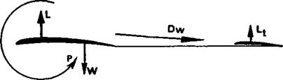
The most usual arrangement of forces for balance with a tailplane. The tailplane is rigged at a slight negative angle of attack relative to the air in its neighbourhood. The tail ‘lift’ is downwards. The additional load must be carried by the wing, and some additional vortex drag, of both tail and wing results.
|L —Lt = W] This is also a safe, stable layout.
To achieve a required new trim the whole tailplane may be moved to the new position, or, more often, it may be provided with a hinged portion, the elevator, which changes both the camber and the effective angle of attack of the tail to produce the same effect A different trim setting is required for qvery different flight condition. If the control is insufficiently powerful, some attitudes may be impossible to hold.
With the centre of gravity in this position, there will always be a download on the tail. It will be rigged at a more negative aerodynamic angle than the mainplane: this difference is often termed ‘decalage’ or ‘longitudinal dihedral’. In a vertical dive the lift is zero and the weight acts vertically, so there is no pitching moment arising from these two forces. The wing camber is still present, however, and its direction is such that it would turn the model through the vertical into a bunt unless balanced by the tailplane. Thus, although the elevator is moved down to produce the dive, and held down to keep the dive going, the tail load is still down. (This is discussed further below.)
Stability and control problems in aircraft are complicated because a model which is stable in pitch, i. e. in nose up and nose down senses, rotating about the crosswise or Y axis (Figure 12.2), may be unstable about the other axes, in yaw, about the vertical, Z, axis and in roll about the fore and aft or X axis. The three axes are assumed to cross one another at right angles through the centre of gravity of the aircraft This conventional system of axes does not imply that the aircraft is somehow bound to rotate, when it rotates, round the axes as if they were skewers.
The axes are in fact no more than convenient reference lines for trim, balance and stability calculations.
12.2 LONGITUDINAL BALANCE AND TRIM
Balance, or trim, and stability are closely connected, but they are distinct Consider balance first If a model is to fly at all, it must be in a balanced trim although being in balance is not enough to guarantee stability. A juggler keeps things balanced despite their instability. If he cannot achieve balance, everything comes crashing down and model aircraft are very similar. Only when balance, or trim, is achieved do questions of stability arise. Stability then may be regarded as restoring balance; the balance must be possible in the first place, if it is to be restored.
For flight in balance, or equilibrium (climbing, diving, or flying level at constant speeds) there must be no tendency of the aircraft to pitch nose up or down. Mathematically, when a model is trimmed for a particular flight attitude the longitudinal moments taken at any convenient point will total zero. On a practical aircraft this means that a state of balance must be possible in all the flight attitudes the pilot is likely to require. Even if the equilibrium is deliberately upset in order to change position (from steep climb to glide, for instance, or from level flight to inverted) if the model is to hold the new attitude for more than an instant, it must be trimmable at this position. The balanced state must be attainable, by use of the controls, over a wide range of attitudes.
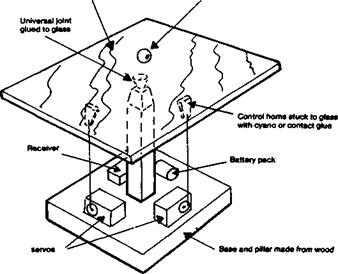
A stable aircraft will always tend to hold its trimmed attitude and an unstable one will always diverge. Between these two conditions is a narrow zone where the model will do neither. This is ‘neutral stability’. A neutrally stable aircraft is less difficult to fly than a truly unstable one. Any change of attitude, however caused, will not be corrected and the next gust or other disturbance will also not be countered, so the aircraft, while not positively diverging, will be at the mercy of every small atmospheric change and will wander away from the trimmed position constantly. A good example of neutral stability is seen in a ground training device sometimes used to teach pilots to fly radio controlled helicopters. A flat table which can be tilted by servo motors under radio control, has a steel bearing ball or marble rolling on its surface. The trainee has to position the ball on the table. Every smallest tilt sets it rolling towards the edge and it keeps on rolling until the table is tilted appropriately to stop it It then has to be tilted the other way to roll the ball to another position, and tilted again to stop it when it gets there!
Sheet glass or mirror Bearing ball
|
Fig. 12.1 Neutral Stability, a helicopter ‘simulator1 in which the trainee pilot must keep the bearing ball on the flat, but tiltable, table (From Dave Day’s book. Flying Model Helicopters). Positive stability corresponds to a shallow dish in place of the table. Instability would replace the table with a domed surface. |
 |
In contrast, a stable aircraft could be imitated by a similar device with a shallow dish instead of a flat plane. Centralising the controls would allow the ball to settle down in the middle. Holding the dish steady in some tilted position would find the ball bearing seeking the new position of the lowest point and it would soon settle there. A truly unstable situation would be to replace the table with a domed surface. A brilliant juggler might be able to keep the ball centred but very few model fliers could do it and the same applies to real model aircraft of all types. Aircraft lacking inherent aerodynamic stability are flown but require automatic stabilising devices, usually of gyroscopic and electronic kinds. They are highly manoeuvrable.
It follows from the above that stability and controllability must be considered together. A stable aircraft will obey the controls predictably because whatever their position at any instant, it will strive to obey them. A genuinely unstable aircraft will, in contrast, not settle down in any position. Every small divergence from the desired flight path will be magnified. If the model is in a shallow dive this will tend to become steeper unless the pilot corrects it. A shallow turn will very quickly become a tightening spiral. If flying inverted, an unstable model will roll over or bunt, unless the pilot makes constant corrections at every moment An unstable radio controlled aeroplane is difficult to fly, although it can be done. A momentary inattention may produce disaster but with extreme concentration the aircraft can be saved. An unstable free-flight model will almost certainly crash.
Even so, too much stability in a radio controlled model can be a liability. Since the forces involved in holding position are relatively powerful, it is evident that changing from one attitude to another requires large forces too. Unless the control surfaces are unusually effective, this makes the over-stable aeroplane sluggish in response to the pilot. If the model is flying towards a tree or some other obstruction, it is very important to have quick response to commands. Hence although a high degree of stability is very desirable for the beginner’s radio controlled model, and for all free-flight aircraft, most model fliers prefer to have only moderate stability for the sake of more immediate control reaction.