As we travel into the higher regions of the atmosphere, or leave it altogether for the wide expanse of space, our speed gets faster and our view of the globe broader. It becomes evident that the Earth is round and rotating with respect to the sun. As travelers, we experience such effects as centrifugal and Coriolis
accelerations and are looking for another immutable reference frame somewhere out there.
This situation motivates us to study the shape of the Earth in more detail. First, I shall give a brief overview of geodesy, the geodetic coordinate system, and the gravitational attraction of the Earth. Then we are prepared to formulate the six-DoF equations of motions in an inertial and geographic format. For the kinematic equations we shall pursue the direction cosine approach rather than use quaternions.
Some of this material should be familiar to you from Chapters 8 and 9. Here, however, we expand our horizon to an elliptical Earth and deal with the mechanics of developing a simulation model for hypersonic vehicles.
10.1.2.1 Geodesy. Geodesy can be defined as the science concerned with the precise positioning of points on the surface of Earth and the determination of the exact size and shape of Earth. It also involves the study of the variations of Earth’s gravitational attraction and the application of these variations to the precise measurements of Earth’s shape.
The science of geodesy is as old as the early Greeks. Whereas Homer lived on a flat Earth, Pythagoras, the mathematician, envisioned the Earth to be fashioned according to a perfect sphere. Of the same opinion was Aristotle, the dominant scientific authority until the Middle Ages.
One of the great pursuits of the ages—and continuing today—is the accurate measurement of the Earth’s circumference. It amazes me to read that Eratosthenes, a Greek scholar experimenting in Egypt, deducted from measurements of sun angles that the circumference at the equator is 25,000 miles. Today we peg it at 24,899 miles. However, when Ptolemy came on the scene, he convinced the majority of the scholars that the number should be revised downward to 18,000 miles. It still stood at that value when Columbus made his plans to sail to India. Fortunately so, because otherwise Columbus may have been unwilling to travel such a great distance and America might have been discovered by Russian cosmonauts peeking down from space!
The Pythagorean spherical concept offers a simple surface, which is mathematically easy to deal with. Many astronomical and navigational computations use it to represent Earth. Although the sphere is a close approximation to the true figure of Earth and satisfactory for many purposes, for the geodesist interested in measuring long distances—spanning continents and oceans—a more exact configuration is necessary.
Because Earth is in fact slightly flattened at the poles and bulges somewhat at the equator, the geometrical figure used in geodesy is an ellipsoid of revolution or spheroid. Two dimensions define a spheroid; the semimajor axis and the flattening parameter. The flattening parameter is defined as the fractional change between the semimajor axis a and semiminor axes b:
Some references also call it the ellipticity of the spheroid and invite some confusion with the term eccentricity, which is defined as
a2-b2
Thanks to the World Geodetic Systems (WGS) Committee, chartered in 1960, the numerical precision of the reference ellipsoid has been refined ever since. Today, we use the WGS 84 (Ref. 3) system with the values a = 6,378,137.0 m and e = 0.08181919.
For completeness’ sake, however, let me point out that the real shape of Earth is arbitrary and is only successively approximated by an alternating series of elliptical and pear-shaped surfaces. So far, our classification is based on geometric considerations only (geometrical geodesy). The WGS 84 ellipsoid is that first approximation beyond the sphere that fits the actual surface of the Earth best (at sea level). Alternately, the actual shape of the Earth is also referred to as geoid. It is defined as that surface to which the oceans would conform over the entire Earth if free to adjust to the combined effect of Earth’s mass attraction and the centrifugal force of Earth’s rotation. Notice the geoid is defined with the aid of physical forces. Therefore, this branch of geodesy is also called physical geodesy.
Do not be intimidated by geodesy. You will never learn all of the tricks of its trade unless you make it your life’s passion. If that is the case, I recommend you start with the book by Torge.4 Fortunately, for six-DoF simulations we are satisfied with the WGS 84 ellipsoidal approximation and do not distinguish between geometrical and physical geodesy.
Briefly review Secs. 3.1 and 3.2. There we define the inertial frame I and the associated inertial coordinate system ]7. The inertial frame’s attitude is fixed in the ecliptic, but the center of Earth is also one of its points. In effect, the inertial frame convects with Earth’s motion around the sun but does not follow Earth’s rotation. The inertial coordinate axes are aligned with the vernal equinox and Earth’s spin axis.
Earth’s frame E, the associated coordinate system ]£, and the geographic coordinate system ]G are also defined in Sec. 3.2. The transformation matrix [T]G£ is a function of longitude and latitude [Eq. (3.13)]. Because in Chapter 3 Earth was presumed to be spherical, latitude was measured from the equator to the geocentric displacement vector of the vehicle. However, for an elliptical Earth model we now have to refine the definition of latitude, while longitude remains the same.
We call the latitude of the WGS 84 model the geodetic latitude kj, and the earlier definition is relabeled the geocentric latitude kc. Figure 10.4 depicts the geometrical situation. To define the geodetic latitude, project the vehicle c. m. В onto the local tangent plane at Bq and continue the plumb line until it crosses the
|
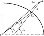
Fig. 10.4 Geocentric and geodetic latitudes.
|
plane through the equator. The angle between the plumb line and the equatorial plane is the geodetic latitude kd. This is the latitude that is used in cartography. If you want to go back to a round Earth, simply use the geocentric latitude kc.
Let us review and revise carefully the definition of the geographic coordinate system. We rename the former geographic system and call it the geocentric coordinate system while maintaining the same symbol ]G. Its 1G and 2G axes are still parallel to the plane normal to sbi and point north and east, respectively, while the 3G axis is parallel and points in the opposite direction of sBits. new entity, the geodetic coordinate system, is required. Its lD and 2° axes are parallel to the plane normal to the plumb line and point north and east, respectively. The 3d axis is parallel to the plumb line, pointing downward. The geodetic and geocentric coordinate systems are related by the deflection angle <5, as indicated in Fig. 10.4, and defined by
 8 = kd — kc
Its value depends on the geodetic latitude kd, the flattening parameter /, and the altitude of the vehicle h. Britting5 has given an approximation
5 = / sin(2krf) (l – L – (10.34)
where Ro is the distance between the points Bo and I, which can be calculated from the Earth’s major axis a, its flattening parameter, and the geodetic latitude of the vehicle
 The accuracy of Ro is better than one meter, and 8 is within 4.5 arcsec at 30 km altitude. The transformation matrix of the geodetic wrt geocentric coordinate systems is governed by this deflection angle 5
(10.36)
For spherical Earth 5 = 0, the geocentric and geodetic coordinate systems coincide.
Given the longitude l (now also called geodetic longitude) and the geodetic latitude kd, the transformation matrix of the geodetic wrt the Earth coordinates is adapted from Eq. (3.13)
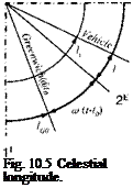
Now regard Fig. 10.5. We can extend Eq. (10.37) to inertial coordinates by replacing the geodetic longitude with the celestial longitude /,, which is measured from the 11 axis. The celestial longitude is composed of the celestial longitude of Greenwich la and the geodetic longitude of the vehicle /, = lG + l. However,
because the Greenwich meridian rotates with the Earth rate co$ during the fly-out time of the vehicle, it increases from its initial location lGo by co$(t — to) becoming lG — lc0 + соф(г — t0). The celestial longitude of the vehicle at time t is then
U — /go + &>®(t — to) + l (10.38)
Substituting /, for / in Eq. (10.37) yields the transformation matrix of the geodetic wrt the inertial coordinate systems
Both transformation matrices will be useful when we build our six-DoF simulations.
Another important kinematic problem is the determination of the inertial position of the vehicle [лД/]/ in inertial coordinates, given the vehicle’s longitude /, latitude kd, altitude h, and initial Greenwich celestial longitude lGo – We start with the displacement vector of the vehicle in geocentric coordinates [sg)]G = [0 0 — (Ro +h), using the approximation Ro+h % , which is according to Bribing5
less than 1 m for endo-atmospheric flight. Ro is given by Eq. (10.35). Then we transform from geocentric to inertial coordinates and obtain the result
M7 = [f]DI[T]DG[sBI]G (10.40)
where the two transformation matrices are given by Eqs. (10.39) and (10.36), respectively.
The inverse problem is the determination of the vehicle’s longitude, latitude, and altitude, given the inertial displacement vector [.?£/]7. Unfortunately, a straight calculation is not possible because the deflection angle itself is a function of latitude. Therefore, we take recourse to an iterative approach that proceeds as follows: 1
2) Start an iterative loop in which you calculate the radius to the ellipse Ro with Eq. (10.35), the altitude h from the approximation h = |sB/| — Rq, and the deflection <5 using Eq. (10.34).
3) Now update the approximation кц Xj + 8 and stop the iterative loop if the improvement drops below a certain value, say 10-7 radians.
4) Finally, calculate the geodetic longitude
/ = arcsin {{sudi/l[(sm)[f + [Cv?/)^]2} – ho ~ coe(t – t0)
In most situations it takes fewer than 10 iterations for convergence. Yet, it is always advisable that you guard against excessive numbers of iterations.
Let us wrap up our adventure in geodesy with an excursion to the modeling of the gravitational field and the resulting gravitational acceleration that acts on the flight vehicle. As we have discussed in Sec. 8.2.2, the force of attraction F between two bodies M and m, separated by the r distance, is according to Newton
 F = G-
where G is the universal gravitational constant. If m represents the flight vehicle and M the Earth, then the acceleration on the vehicle is
_F _GM
^ m r2
If the Earth were a perfect sphere of uniform density, g would sweep out a gravitational field consisting of concentric spheres. Yet, Earth being a geoid, we have to call the mathematicians for help. They invented the spherical harmonics that successively improve the representation of the gravitational field. The first term represents the sphere, and, together with the second term, the desired model of an elliptical gravitational field is reached.
|
— 3n/5C2 0 (I sinkceoskc ’ \sbiJ
0
.1 + 5’/5<ri’”(i^)!(3si"Ji’"[3].
|
The WGS folks have worked since 1960 to improve this elliptical gravitational model. In 1984 they determined that the value of GM is 3.986005 x 10¹⁴ m3/s2 and that the second-degree zonal gravitational coefficient is C2.0 = —4.841668 x 10⁻⁴. The acceleration acting on a vehicle caused by the gravitational reference ellipsoid is given in geocentric coordinates as
with all variables already defined. The main contribution is in the 3G direction. If you neglect the ellipticity, i. e., Сг, о = 0, you recover the spherical value of g = GM/sbi2- Notice, because of symmetry, there is no gravitational component in the east direction.
Hitherto, we have labored through the preliminaries of modeling an elliptical Earth. You will use most of these equations to build the utility routines for your six-DoF simulation. In particular, you will have to program a subroutine that
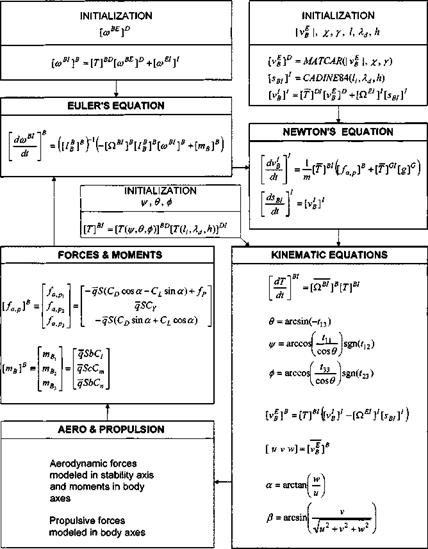
calculates [T]GI, given /, Xd, h (called CADTGI84 in CADAC); another one that determines l, Xd, h, given [лд/]7 (called CADGE084 in CADAC); and the inverse that provides [ід/]7, given /, Xd, h (called CADINE84 in CADAC). You find these subroutines in CADAC utility file UTL3.FOR on the CADAC CD. Finally, the gravitational acceleration is given by Eq. (10.41) (in the CADAC GHAME6 simulation, Module G2, subroutine G2GRAV). Now we are prepared to derive the equations of motions.
![]() -bxb2b2 – Ьф3ь3 – b2bb – Ъ2ь3Ъ3 – ЬзЬфі – b3b2b2
-bxb2b2 – Ьф3ь3 – b2bb – Ъ2ь3Ъ3 – ЬзЬфі – b3b2b2


 5 = + -тв]В) (10.44)
 The accuracy of Ro is better than one meter, and 8 is within 4.5 arcsec at 30 km altitude. The transformation matrix of the geodetic wrt geocentric coordinate systems is governed by this deflection angle 5




 Dslf + nSElf – =mB
 + inSE]S[lS]S([‘Js]s+ [**]*) = [mB]s

 h ( + hcor’ – p’r’ih – h) = тв2
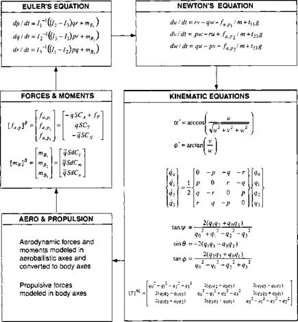
![Aircraft equations Подпись: = 7-7—ТгШ^зз - 4 - thy — 1з(Нъ + h — h)p — + ^зз mBl — І]з,твг = 7-{[(/33 - I и )P ~ IRY + Іізір2 ~ r2) + mB2} n - 1 2 {[(-Inh + I^ + ^)P -*11 -*33 ~ і 13 + НъУъъ + I\ — h)r + Iuh]q + 1\шВъ — InmBl}](/img/3132/image890.gif)
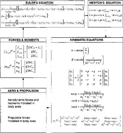
 (10.15)
 + m[QBE]B[vE]B = [fa, p]B+m[g]B
 + m[0.BE]B[ vE]B = [fa, p]B + m[T]BL[g]L (10.2)
 (10.6)
 + [Qbe]b[Ib]B[wbe]b = [mB]B (10.9)
 (10.11)


