Our heavyweight helicopter equal in the world does not have
In Rostov started production of the most load-lifting rotary-wing car The Russian holding «Helicopt[...]

Everything about aircrafts and helicopters. News and events in aviation worldwide. Civil, transportation, military helicopters and airplanes.

Everything about aircrafts and helicopters. News and events in aviation worldwide. Civil, transportation, military helicopters and airplanes.

Everything about aircrafts and helicopters. News and events in aviation worldwide. Civil, transportation, military helicopters and airplanes.

Everything about aircrafts and helicopters. News and events in aviation worldwide. Civil, transportation, military helicopters and airplanes.


Accurate computer codes arc CFD-codcs based on solutions of the Euler equations, sometimes with a coupled boundary layer solution and solutions of the Navier-Stokes equations. They arc
used for:
• configuration optimisation, to check and improve the previous design steps based on simpler codes, and to include wind tunnel results.
• interference drag reduction, which is impossible using simpler codes.
• inlet and nozzle design with strong shock/boundary layer interactions.
To allow efficient exploitation of CFD-codcs. these codes must fulfill the following requirements:
• They must represent the relevant physical properties. For SCT design, these arc: reliable radiation of disturbances (not fulfilled by most CFD-codcs). prediction of shocks and shock reflections.
prediction of separations (this still requires much research on turbulence).
• They must be able to use the exact geometry definitions including suited numerical grids.
• They must provide insight in flow physics by visualisation postprocessing of results.
• They must be able to predict aerodynamic loads.
• They must provide reliable performance predictions (drag prediction is still difficult for most CFD-codcs).
• They must be able to identify the different physical contributions of drag (still a research task, especially for supersonic flow with strong radiation properties).
• They must provide reliable aerodynamic derivatives for flight mechanics calculations.
• They must support the analysis of experiments.
If these codes are only used to check results of previous calculations, the old fashioned procedure of man hour consuming grid adaption and numerical fine tuning may be applied. But as soon as the code is used for configuration optimisation, new requirements must be fulfilled.
• A geometry generator with very few variable parameters must model the variations of interest which the optimizer has to investigate.
• The grid generator must automatically provide a suited high quality grid.
• The code must fast and automatically converge to a useful result. If the code breaks down, a (bad) result must be provided which directs the optimizer to useful variations.
• The results produced by the optimizer’s parameter variations must reflect the variation of physical results
In the first interdisciplinary design loop, the w hole aircraft is investigated. To allow the optimizer an investigation of the whole flight mission with a sufficient number of configurations, the individual calculations must be very fast and use only few variables. In more detailed investigations. not all disciplines arc involved ai (he same time and perhaps not all mission points. The aerodynamic code can therefore use more time and variables to become more accurate As a result. available turn around time, variable* involved and accuracy achieved rise from step to step until the ultimate step of the flying aircraft.
As long as design modifications by theoretical predictions arc relevant, turn around times arc needed which allow for many repeated design loops. This is, depending on the step: one hour, one night, one weekend Fast codes arc all codes which allow for turn around times of one hour for pure aerodynamic calculations (with many individual code calls) or one night/ weekend for interdisciplinary tasks.
Very fast codes are closed foimulas for the interdisciplinary investigations. They only need some main geometry parameters as input for global estimation of aircraft performance to allow configuration selection.
Fast codes relay on linearised theory with empirical corrections. They need more geometry parameters to allow for a first aerodynamic design optimisation including volume distribution and a first approximation of tw ist and camber: and they check the aerodynamic predictions in the interdisciplinary model.
Both codes calculate (at different accuracy levels) the global aerodynamic coefficients for performance calculations and first flight mechanics estimations. They identify the physical drag contributors and provide a load estimation
As any code used for numerical optimisation, the codes must be robust. This means:
The code should be able to calculate all problems which the optimizer may pose If the code breaks down, this must not stop the design process, but the code should deliver an inacccptahly bad result which is the worse the heavier (lie code crash was. For instance, if negative pressures occur, the result can be a bad value proportional to the detected negative pressure value. This leads an optimizer to solutions, where the code docs not crash If the code is reliable, only those arc interesting solutions. Such eases must be controlled by the design engineer!
Today, most research effort is devoted to highly sophisticated CFD-codcs. These codes are needed and must be unproved furthermore, but for a better and practical interdisciplinary aircraft optimisation, quality and applicability of the simple fast codes must be improved Much more research effort is needed in this direction.
Aerodynamic design is development of a suited shape. For SCT development, extensive application of numerical opumi/ers is required. When using optimizers, the first very important step is to describe the space of possible shapes by as few parameters as possible, but still without in – acccptahlc restrictions. In the first step of interdisciplinary optimisation, only global parameters
arc needed to described the basic aircraft geometry. The more refined the investigations arc, the more sophisticated the numerical methods are. the more detailed the geometry must be described. But for all levels the same requirements for geometry generation hold:
• For geometry generation by a human design engineer:
Geometry must be described by a limited set of parameters. But those parameters must be meaningful and well ordered in order to allow a human to reach geometric design goals. Alternative ways are allowed, e g multiple parameter sets or parameter set selections.
• For automatic geometry generation by a numerical optimizer
Geometry must be described by as few independent parameters as possible. Those parameters may have any level of abstraction. Not allowed arc alternatives to the optimizer for selection between different, but equivalent parameter scis.
• Any geometry generator must provide smooth shapes without tending to wiggles:
If wiggles cannot be avoided, smoothing procedures must be provided. For human applications, the smoothing procedures can be applied off-line as the Iasi step of geometry generation. For numerical optimizers smoothing, if not avoidable, must be included in the geometry generation.
• Any geometry generator must provide interfaces to and from CAD-systems:
When aerodynamics has developed a shape, this shape will be transferred to oilier company work groups like project, structure, acroelastics, model design and fabrication All aircraft related data transfer uses CAD-systems. The aerodynamic shape therefore has to be transferred into the CAD-system without intolerable accuracy losses.
On the other side, aerodynamics has to use input from other departments for geometry constraints like fainng size etc. Or the real model geometry has to be checked prior to a wind tunnel test. Or geometries generated by a partner must be investigated. Or wind tunnel results • like pressure measurements – have to be applied to a given geometry for aerodynamic improvements. In all those cases it must be possible to transfer the CAD- geometry mm the aerodynamic geometry generator as an input geometry, e. g. to start an improvement calculation.
Especially for application of numerical optimisation strategies more progress in systematic shape definition is needed. Sometimes a is proposed to use CAD-systems directly for geometry generation, but CAD-systems arc oriented towards structural design: these do not contain geometry definition tools suitable for aerodynamic optimisation. Powerful aerodynamic 3D-geometry generators arc under development as preprocessors for CAD systems, see hook chapter 9.
Concorde has inacccptable take-off noise levels. For a Concorde-type SCT lower noise levels can only be achieved using larger engine diameters and larger wing span. To maintain or even increase cruise performance, wing thickness will have to be reduced. Such wings become very flutter sensitive.
Aerodynamic damping is an indicator for flutter onset. It is the smaller, the higher the flight speed is. At high subsonic speeds, nonlinear transonic aerodynamics reduce aerodynamic damping, the so called transonic dip (Figure 33) (74). A new SCT has therefore to be investigated for flutter at transonic and supersonic cruise speeds.
 aerodynamic
damping
Figure 33 Transonic Dip
Because of flutter becoming very critical for the thin wings of symmetric (Concorde – like) SCT-configurauons. at least a rough approximation of flutter tendencies must be included in the first steps of configuration optimisation. Hitherto nobody knows how to do it. Perhaps artificial flutter damping can help, if its certification becomes possible.
5.8.1 Static aeroelastics
In classical aerodynamic design, the aircraft shape is designed for one design point M(: (cruise Mach at a given weight and altitude). Knowledge based margins provide the ability to cope with the off-design points. Some still cover the (cruise) flight regime (like Мод = maximum operating Mach. Mcs e subsonic cruise Mach, other aircraft weights for begin of cruise or end of cruise, altitude variations…). Others concern exceptional points which do not occur in normal cruise, but only e g. for emergencies like MD (dive Mach).
Aerodynamics assume the geometry to be rigid Once the aerodynamic shape is fixed and the aerodynamic loads arc known, structure loads arc determined, structure is designed and static aeroelastic deformation is calculated. This deformation at the design point is taken into account when the shape to be built is defined. The procedure reestablishes the designed aerodynamic shape at the design point flight loads (Mc. design weight and altitude). For any deviation of the design point the aircraft will have a different shape. This deviation becomes important if the wing is not very stiff and if the deviations from the design point are large. Both occur for SCTs with thin wings and multipoint design conditions.
To find the best compromise for an clastic wing flying at different design points, acroc – lastic deformation must be considered in the aerodynamic design. For aerodynamics this can be a rather simple formulation, like a beam formulation for a slender arrow wing or an OFW. or a simple shell formulation for some kind of delta wing, including bending and torsion. The difficult problem is the ‘simple” estimation of structural values because this requires simultaneous estimation of loads, mass distribution and structural thicknesses.
Wind tunnel experiments are essential
• lo get insight into still unknown (low physics, like separation, turbulence, transition.
• to validate numerical calculations.
• to generate data for complicated configurations including interference effects.
• to check aerodynamic design cases and to generate data for improvement strategics.
• to establish aerodynamic data for pre-flight validation of new aircraft.
Wind tunnels have limitations as well. For SCT development the most important limitations for wind tunnel investigations are:
Reynold* number:
Reynolds number in wind tunnel testing usually is an order of magnitude lower than in free flight, for supersonic testing often up to two orders of magnitude For drag measurements the boundary layer is tripped; i. e. transition strips provoke transition from laminar to turbulent flow at defined positions. This allows for calibrated friction measurements, but the boundary layer i* thicker at lower Reynolds numbers. Therefore the interference effects, especially shock/boundary layer interference, in the wind tunnel remain different compared lo free flight. Technologies to transpose interference prediction from wind tunnel to free flight need to be developed
Transition control:
Transition strips must be as small a* possible. Thick or wide transition strips generate too much strip drag and thicken the boundary layer. On the other hand, if transition strips are too small, no transition or even reiaminarisation occurs which does not allow useful drag measurements. The control of transition in experiments, i. e. to identify the laminar and turbulent boundary layer regions on the whole aircraft model is always required Most common transition control methods – like the acenaphtenc technique – require w ind tunnel runs at constant flow conditions. This is impossible in wind tunnels of Mow-down type; and many supersonic wind tunnels are blow-down tunnels. Other transition control technologies are required here, possibly the techniques devoleped for cryogenic wind tunnels (like highly sensitive infrared measurements lean be adapted here.
Testing around Mach 1:
At near sonic speeds the flow around ihe model contains large supersonic flow domains. In the supersonic regions the wind tunnel model radiates disturbances to the wind tunnel wall and arc (at least partially) reflected by the wall back onto the model. In contrast to free flight conditions, this reflection strongly changes pressures and flow properties at the model.
At high subsonic speeds, the supersonic regions can reach the wall and so generate a choked supersonic nozzle flow over the aircraft instead of the open supersonic bubble over the free flying aircraft. This (partial) nozzle flow changes the whole flow field and docs not further resemble to free flight conditions.
Most transonic wind tunnels have slotted or perforated walls in order to minimize wall reflections. This minimisation, though, is only sufficient if the supersonic bubble does not reach the wall or the important reflections do not meet ihe model. This requires test flow conditions avoiding the vicinity of Mach I. New transonic wind tunnels use flexible (adaptive) walls, where the wall geometry is adapted during the lest to follow a free stream path line. This allows for better adaption of near sonic test conditions, but quality of adaption depends on the technical concept of the adaption mechanism: usually only a plane w all adaption is possible for two of the four walls surrounding the test chamber. Although two-dimensional adaption in the most important direction is much better than no adaption, three-dimensional adaption for three-dimensional models remains impossible.
Engine simulation:
Usually, engines in supersonic tests are modelled by simple through-flow nozzles, but it seems impossible to design spillage-free through-flow nozzles: nozzles arc choked, whereas an engine adds energy. Wind tunnel simulation is restricted therefore to cases including spillage. Additional nozzle base drag is created due to the choked flow. It can be corrected by pressure measurements on the nozzle, but these will correct only the individual nozzle base drag, not the additional interference wave drag
Laminar tests:
There is not yet any wind tunnel available for supersonic laminar flow tests between Mach 1.5 and 2.5. At the University of Stuttgart. Germany, a facility is refurbished which • hopefully – will be suited. See also the special chapter 18 on laminar flow for supersonic transports
Measuremeni techniques have been developed for exploiting wind tunnel experiments. Some of these techniques arc state of the art and provided by all wind tunnels: force measurement and pressure measurement via small holes in the model surface. The simpler optical methods like shadowgraphs. Schlicrcn or interferograms are best suited for 2D-measurcmcnts and available where suited. More refined techniques arc available and will be applied to supersonic testing, especially optical methods for flow field measurements:
Pressure sensitive paint (PSP):
Special paints arc developed which, when illuminated by a special light source, emit light depending on the amount of (^-molecules embedded in the paint surface. In air the amount of Os-molcculcs directly correlates to air density. This allows for a direct measurement of air density distribution on the model surface and. when temperature is known, indirectly for the measurement of pressure distribution, see. e g. (69). (70). (71). This technique is new and needs further improvements before it can be applied as a stand alone pressure measurement technique. Especially paint thickness or durability, painting, illumination technique and related automatic data processing need further research.
Liquid crystal coatings:
Surface coalings based on liquid cristal technology allow for various mapping techniques of relevant flow parameters on the model’s surface like shear stress and temperature. This allows simultaneous measurement on large parts of the model. Problems result from the relatively rough coating surface, die limited view angles and often the multiple sensitivities of the coatings which require careful separation of the measured effects. These problems presently still allow only for limited use of the technique in aerodynamic measurements.
Distribution measurements in the free flow field:
Several new techniques allow for measurements in a selected plane of the flow field. Most common is Particle Image Velocity (PIV). see e g. (72): The (low field of interest is seeded with microscopic particles, commonly droplets of about I pm diameter. In the plane of interest, those droplets are photographed twice within a short time interval. The movement of the droplets is identified to provide the droplet s speed which is equal to flow velocity except within a shock. New developments are aimed at larger measurement fields and measuring all three velocity components In the future. PIV measurements will be usable even for complicated interference flow measurements.
Several other flow field measurement techniques arc under development but either still in their infancy, restricted to high Mach numbers, suitable only for very specific cases or just of poor accuracy.
Laser-Doppler anemometry:
In the last years Lascr-Doppler Anemometry (LDA) was developed as a tool for accurate, pointwise, non intrusive flow field measurements |73|. The flow is seeded with droplets (like for PIV) which are observed within a small measurement volume. This volume is established by the crossing of two laser beams, where interference produces a sequence of light and shadow like a grid. Observed is the motion of the droplets through the inter-
fercnee grid, where the frequency of reflected light spots is correlated to the droplet’s speed. LDA allows for accurate measuring of mean and fluctuating values, even resolution of boundary layer flow, but it requires relatively long measurement lime.
Complementary to the experimental measurements correction methods for experimental errors or insufficient simulation are needed The most important corrections required are:
• accurate correction of wall interference.
• correction of Reynolds effects, especially for imerferencies.
• spillage and nozzle base drag correction, especially for flows without spillage.
3.5.1 Supersonic hinge lines
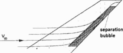
At control surfaces with supersonic hinge lines, shocks occur at the hinge line. Shocks produce pressure losses and so reduce flap effectiveness Additionally, the shock can provoke boundary layer separation bubbles (Figure 30); pressure in those bubbles is lower than behind the final shock. This reduces the flap force significantly. Because of the system of the three shocks behaving very sensitive to variations in the incoming flow and to fluctuations in the separation bubble. strong vibration loads can arise
3.5.2 Trailing edge flaps on highly swept wings
On wings with highly swept (subsonic) trailing edges (OFW. arrow wings), the boundary layer is deflected by the spanwise pressure gradients and tends to become nearly parallel to (lie trailing edge, or even separates (Figure 32). Tendencies known from lower sweep angles, and results for very high sweep angles, are not conclusive. Further theoretical and experimental investigations
arc required to understand flap efficiency at relevant sweep angles.
|
Figure 32 Highly Swept Trailing Edge |
Around flight Mach number I strong normal shocks are generated These arc very sensitive to small changes of the flow field and tend to oscillations.
Control flaps have to produce aerodynamic forces by pressure differences between the flap sales and adjacent wing area. Usually they generate a pressure rise on one side and a pressure drop on the other. Near Mach I the pressure rise at the hinge line provokes a strong shock with strong boundary layer interference This easily results in vibrating loads (buffet) and weakens the flap’s control forces. During transonic acceleration, therefore, the aircraft should not require strong control forces Suited control flaps have swept hinge lines, hinge lines in less ent –
ical regions (for instance close to the trailing edge of the wing), or moving tails.
Engine efficiency is critical at low supersonic speeds. Especially the inlets have to cope with rapidly varying conditions due to sensitive Mach angle variations. The shock system, designed for supersonic cruise, cannot yet establish; an inlet control mechanism, designed only for supersonic cruise shocks, does not work. Measures arc required, therefore, to allow for sufficient inlet efficiency, like special inlet doors.
3.5 Tasks:
At high subsonic cruise optimize L/D:
• avoid separation.
• minimize induced drag.
For transonic acceleration:
• minimi/.*’ wave drag which is dominated by interference effects.
• provide control of the aircraft.
• provide control of engine inlet and nozzle.
Supersonic aircraft is firstly optimized for supersonic cruise performance. To achieve good transonic (i. c. high subsonic) cruise performance, it can be necessary to adapt the configuration to the different requirements The OFW performs this by adaption of sweep A symmetric config – uralion (like Concorde) can use flaps:
• leading edge flaps, to avoid leading edge separation; this is especially important for sharp (supersonic) leading edges.
• trailing edge flaps to control lift distribution for minimization of induced drag and load control during manocuvcrs; this requires a pitch control surface like a horizontal tail.
5.4.3 Low supersonic acceleration flight
During transonic (i. e. low supersonic) acceleration, wave drag is dominant Here it strongly depends on interference of the different parts of the aircraft: fuselage, wing, nacelles with engine stream tubes, tail. Near Mach I even small changes in Mach number produce strong changes in Mach angle (i. e. radiation direction); strong shocks prevail with considerable shock-boundary layer interaction. As a consequence, accurate drag prediction of the transonic interference phenomena requires nonlinear methods including ihe simulation of viscous effects.
5.4.1 Main properties of physics of transonic flow
If the flow field contains parts with subsonic flow and other parts with supersonic flow, the problem is called rransonic Properties in the flow Held strongly change:
• In the subsonic parts, the flow field balances all flow properties in the field and is described by elliptic balance equations.
• In the supersonic parts, the flow field cannot balance properties because flow speed is higher than information speed; it is described by hyperbolic radiation equations.
The supersonic parts usually are terminated by a strong shock. Whereas supersonic oblique shocks usually are kinematically fixed to the geometry, the strong normal shocks in transonic flow evolve in the flow field and are controlled by flow forces. Therefore they are prone to oscillations
5.4.2 Mathematics of transonic flow
Mathematical models describing gas dynamics of those different flow types arc strongly nonlinear. the equations are of mixed elliptic • hyperbolic type, even for the in vise id parts. Computational analysis usually follows transient formulations to model type changes within the flow. These enable elliptic, hyperbolic and parabolic solution procedures. Some models may be used for design purposes to calculate flows with desirable aerodynamic properties, see book chapter 7.