Our heavyweight helicopter equal in the world does not have
In Rostov started production of the most load-lifting rotary-wing car The Russian holding «Helicopt[...]

Everything about aircrafts and helicopters. News and events in aviation worldwide. Civil, transportation, military helicopters and airplanes.

Everything about aircrafts and helicopters. News and events in aviation worldwide. Civil, transportation, military helicopters and airplanes.

Everything about aircrafts and helicopters. News and events in aviation worldwide. Civil, transportation, military helicopters and airplanes.

Everything about aircrafts and helicopters. News and events in aviation worldwide. Civil, transportation, military helicopters and airplanes.


Supersonic cruise is the longest cruise leg on those routes which arc of interest for supersonic transport. So supersonic cruise performance largely determines range, weight and cost of an SCT. Supersonic cruise performance strongly relics on aerodynamic drag reduction. Drag related weights (i. c fuel and engine size) contribute about 60^ to the SCTsMTOW (maximum takeoff weight).
Here, we concentrate on drag reduction. Although, it has to be remembered, that drag minimization for itself is no goal for an aircraft: aerodynamic performance is L/D which is Lift divided by Drag or weight divided by drag; but. when looking for performance, more weight requires an equivalent increase in fuel consumption, see e g Brcguet’s formula, cqs. (44) to (47). A careful balance must be achieved when drag reduction requires a weight increase.
To estimate the influence of individual contributions to supersonic cruise drag, we look at the composition of (supersonic) drag. Contributors are skin fnction drag, volume wave drag, lift dependent wave drag and induced drag. This is for the drag coefficient CD
C„ = A/S Cf + K, I28Vj/<hs£) + K, p2SCj/(2ic/J) + K, SC[/iKbJ) (49)
or in physical units for the drag D
D = ACfq + A„ • 128V2/{kI40) q + K, ■ tfw1 /(Inql1) + Кj ■ W2/{nqb2) (50) with
A: total surface
b; span
Cp: drag coefficient
Q: friction coefficient
CL: lift coefficient
D: drag
K|.- shape parameter for induced drag (Osswald factor)
KL: shape parameter for lift dependent wave drag
Kyi shape parameter for volume wave drag
I; lifting length
1^ total (aircraft) length
M: Mach number
q: dynamic pressure
S: wing (reference) area
V: volume (aircraft ♦ engine stream tube variation)
W: weight
and
[Г = АГ – 1 (51)
In the formulas (49) and (50) some parts are bold faced These arc the contributors which can significantly be influenced by design.
Skin friction drag:
The first term describes friction drag which is mainly determined by the aircraft’s total surface A and the friction coefficient Cf. For minimization both must be minimized.
Total aircraft surface A depends on the specified payload and the required fuel volume, aerodynamic lift, the slenderness and span requirements of other drag part minimization and (weakly) the aircraft’s mechanical strength and stiffness. The total surface minimization is no goal for its ow n, it is rather only one aspect of drag minimization to be balanced with other requirements.
Friction coefficient Cf here is the mean value of the local friction coefficients, weighted by surface area. It is mainly determined by the local Rcynolds-numbcrs. But it may be reduced by drag reduction techniques, those which are most well known arc laminarization and riblcts
Laminarization maintains the low drag of laminar flow in the boundary layer, which reduces local Cf values for an SCT by about 90%, but requires a huge technology effort (see special lecture). Presently, we design our SCTs without laminar flow, although laminar flow promises strong improvements. But an SCT which will become viable only with application of laminar flow, may loose its competitiveness with subsonic aircraft as soon as the subsonic aircraft utilizes laminar flow’. Must likely, subsonic aircraft will apply laminar flow earlier than SCTs. On the other hand, an SCT concept which is viable without laminar flow, may be improved by laminar flow just like the competing subsonic aircraft.
Riblets are streamwisc microscopic valleys in the aircraft’s surface which reduce aircraft turbulent drag locally by about 8Я (49).
Other measures to reduce skin friction may arise in ihe future. Special surface coatings (50) such as some nano materials (thickness of only a few molecules) have been proposed which alter the wall condition ("no slip") for the boundary layer flow, e g. by not completely diffuse reflection of the air molecules at the wall.
Volume wave drag:
The second term describes volume wave drag w hich is mainly determined by the aircraft’s volume V and strongly by slenderness V/l^. because l0 is squared and the whole term (V/
ly2)‘ is squared once more
Total aircraft volume V is. like surface A. given with the specified payload and the required fuel volume, the aircraft’s mechanical strength and stiffness and the slenderness and span requirements. Due to the important volume wave drag contribution, volume of
supersonic aircraft must be minimized, see Concorde’s narrow and uncomfortable fuselage.
Larger total aircraft length l0 decreases volume wave drag and decreases juncture strength as well so that it increases aircraft weight and reduces stiffness. Both have to be kept in acceptable boundaries. Especially for large SCTs. i. e. long fuselages, fuselage flexibility poses big problems.
After Concorde s first landing at the old airport in Singapore, the pilots – although carefully fixed with seat bells in the tiny cockpit – hit the overhead panels with their heads due to strong bending oscillations of the slender fuselage on the rough runway. This was. for a long time, the last Concorde landing in Singapore.
Today airports request a maximum fuselage length of about 80 m, although most large SCT-designs (250 or more passengers) have fuselages of more than 90 m which is at the flexibility and weight limits.
The shape parameter Kv depends on the volume distribution of the whole aircraft including cross sectional variations of the engine stream tubes At M= I this is simply the distribution of the area normal to the flow direction (because Mach angle ц is 90"). At higher Mach numbers it becomes more complicated:
From each point of the aircraft’s surface a perturbation wave is radiated downstream along э conoid which opens with Mach angle ц around the stream line.
sinfi = 1/Л/ (52)
the Mach conoid, see Figure 13. Therefore all areas along Mach conoids from and towards each surface point have to be respected. In practical applications for slender configurations, the following double integral approximation is used to compute the area distribution of an equivalent body of revolution: on the most important perturbation line (e. g. the fuselage center line), the contributions of one Mach cone (of the undisturbed flow) are collected by integrating the cross sectional areas which are cut by a sufficient number of tangent planes to the Mach cone, so-called Mach planes (about 24 or more), which osculate around the generating Mach cone, along the perturbation line (center line) the contributions of several generating Mach cones (about 30 or more) arc summed up (51]. see Figure 14. As long as the aircraft is slender it does not strongly alter the speed of the incoming flow; therefore the simple area approximation using the Mach planes of the incoming flow is valid. An aircraft which produces strong perturbations, will never be efficient For simple bodies of revolution, the minimum drag area distribution is given by the Sears-Haack area distribution (52). (53].
 |
Figure 13 Mach Conoid and Mach Cone
Figure 14 Wave Drag Calculation I’sing Mach Planes Lift dependent wave drag:
The third term describes the lift dependent wave drag. It depends on speed (p2 or fJ2 / q). aircraft weight W and aircraft lifting length 1.
Lift dependent wave drag rises quadraiically with weight W* or Q.2, like the induced drag in the last term. But whereas the induced drag lowers with speed (q), the lift dependent wave drag increases with speed ф" / q – l • 1/M2).
Lift dependent wave drag lowers quadraiically with lifting length l‘. requesting a slender wing with high sweep and small span.
The shape parameter KL is minimized by a smooth elliptical lift distribution along lifting length I. Computation is demonstrated in other lectures and [54].
Induced drag:
The last term describes the well know n induced drag, lb nondimenMonal value C^. which is referenced to wing area S. rises with lift coefficient squared Cl“ and decreases with aspect ratio b2/S; but in physical units it rises with weight squared W* and decreases with dynamic pressure q (speed squared) and span squared b*.
Therefore: minimum induced drag requires a high span (b‘)
The shape factor K| is the well know n Osswald factor, which becomes 1 for elliptical lift distribution over the span, see e. g. 155]. Elliptical lift distribution is achieved by plane w mgs of elliptical planform distribution and nearly by plane delta wings (as long as there is no leading edge separation). Best performance is reached with subsonic leading and tfailing edges, i. e edges within the Mach cone For supersonic edges, in general the suction force is lost which is required for minimum induced drag. Pure supersonic wings (supersonic leading and trailing edges) have the maximum lift dependent drag of
CD « Cetane* (53)
For other (wing) planforms, elliptical lift distribution can be approximated for one angle of attack by suited twist and camber distributions. Deviations of this design a produce additional induced drag according to the (wing) planform.
Summary:
To minimize supersonic drag we have to minimize certain flow parameters which requires to optimize some configuration geometry parameters:
minimize friction drag by optimizing surface geometry atul quality (lammarization). minimize volume wave drag by optimizing slenderness and -olume, minimize lift dependent wave drag by optimizing wing slenderness. minimize induced drag by optimizing span. resp. aspect ratio.
Wave drag minimization requires slender configurations and slender wings, i. e. low ЬЛ. whereas induced drag requests for high span b. Task is. to find the best combination of b and I, represented by the size of the rectangle
b 1 or b-1, (54)
given by span b and lifting length l or overall length lD(see Figure 15).
![]()
 |
 |
Classical (Concorde type) SCT
The classical Concorde-like configuration only provides relatively low span for acceptable slenderness with (at least partially) subsonic leading edges. Because the leading edge is swept in different directions, it provides only half of the maximum possible lifting length I for a given span b and sweep angle In contrast, the oblique flying wing (OFW) provides the maximum rectangle size b l=b I0 because the wing uses the whole diagonal. Indeed, the elliptical OFW’ is the best solution reaching the theoretical drag minimum which was demonstrated by R. T. Jones (561.
J. Merten*
Daimler-Benz Aerospace Airbus GmbH, Bremen, Germany
4.1 Introduction
In the chapter “Son of Coocorde. a Technology Challenge" one of the new challenges for a Supersonic Commercial Transport (SCT) is multi-point design for the four main design points
• supersonic cruise.
• transonic cruise,
• take-off and landing.
• transonic acceleration.
Besides engine technology, aerodynamics is most challenged by these differing requirements. But aerodynamic solutions will only become viable when contributing to an optimum of the whole aircraft, which is to be found in cooperation with all disciplines Here, we deal only with the most important aerodynamic parameters at the different design points and consequences for aerodynamic design
A "classical’ Concorde-hke design w ill be required to reach technology limits of all relevant disciplines This requires perfect harmonization of all aspects in the design.
An unconventional configuration can improve performance over the limits of the "classical’’ configuration. But it requires a new kind of cooperation between the individual disciplines. with dissimilar interfaces between the disciplines compared to the "classical" approach.
In both cases, a solution will only be reached by using the tools of Multidisciplinary Design Optimization (MDO) which is treated in more detail in several lectures of this course. There arc three objectives of MDO. each of them of equal importance.
Harmonize multiple disciplines:
Organize cooperation and data transfer among all relevant disciplines.
Although all over the world companies talk about introducing MDO. total quality management (TQM), concurrent engineering (CE) etc., in real life there are strong objections of hierarchies against any kind of cooperation between departments. The future will show if market competition will improve the situation.
Cooperative design:
Data to be respected for harmonization have to be carefully selected and must be ordered from crude prcdcsign to detailed final design. Data transfer from pre design to the more detailed design steps and vice versa must be organized and fit into the data selected for interdisciplinary transfer.
Combine the relevant data into a design which must be evaluated by all participating disciplines
The design process must be able to update the design exploiting the data corrections occurring in the cooperative evaluation.
Optimization:
Use optimization tools which are well adapted to the different design stages in order to
exploit the best combination of the available technologies. Especially for interdisciplinary work, numerical optimisation is recommended.
MDO is the key technology for a new supersonic transport. For subsonic transports remarkable improvements arc also expected
Most systems ore comparable with the ones of subsonic aircrafts. Emphasis is on low weight, small space and possibly high temperatures. Special systems for SCT are:
Inlet and nozzle control
Supersonic engines work at subsonic speeds. Inlet must decelerate the flow to subsonic speed, the nozzle must adapt to free stream pressure Especially inlet control with several shocks and tuning w ith nozzle stale is especially challenging. Concorde’s solution is sull state-of-the-art.
(‘(i-eontrol
From subsonic to supersonic flight, the center of pressure varies strongly. Control is provided by center of gravity (CG) control via fuel transfer. This system is proved in Concorde and applied in several subsonic jets as well.
Scheduled systems
in order to meet noise requirements at take-off and landing, it is envisaged to use an automated system for scheduling of flight path, flap settings and engine controls This is envisaged for subsonic aircraft as well. But for an SCT it will be more complicated, and an SCT will be more dependent on such a system.
Engines must fulfill several requirements at different design points, like the aircraft Efficiency:
SCT-engines must be very efficient at supersonic and high subsonic cruise, and must provide sufficient thrust at take-off. transonic (low supersonic) acceleration and cruise.
Emissions:
To protect the atmosphere, pollution has to be minimized. Especially low NO,-bumers must be developed. This is even more stringent than for subsonic aircraft, because SCT fly higher and burn at higher temperatures during cruise.
Noise:
Engine noise during take-off and landing must be comparable to subsonic aircraft (ICAO annex 16. chapter 3; FAR 36. stage 3). This requires large nozzle exit areas, comparable to subsonic aircraft of the same weight.
The multipoint capabilities of the engines are strongly related to the configuration selected For example thrust available during take-off and landing depends on engine bypass ratio, noise reduction by suppression or simply throttling down, possible integration of noise suppressors in the airframe etc. This influences engine weight, and thrust available and engine efficiency in the other design points. On the other hand, thrust required in the design points is determined by the configuration, mainly aerodynamic performance and weight.
An SCT has only a small payload fraction; therefore it becomes very weight sensitive. To make a Concorde-like SCT viable, the necessary reduction of structure weight (compared to available technology, e g A340) will be about
30% for a Mach 1.6 SCT 40% for a Mach 2.0 SCT 50% for a Mach 2.4 SCT.
Even when considering for the high unit price of an SCT. this seems to be very risky’ But still some improvements in other technologies, especially configuration selection, may reduce the weight improvement requirements given above
New Materials:
For Mach numbers below 1.8. highest temperatures occur in sunshine on ihc ground. For Mach numbers above 1.8. cruise temperature becomes important, especially in respect to life time Below Mach 2.0. emphasis for the airframe is still more on light weight than on temperature Some materials envisaged arc carbon fibers (CFRP), metal matrix composites (MMC) for highly loaded parts and ceramics.
For supersonic engines creep resistant high temperature matenals are required (peak temperature at cruise).
Manufacture:
New methods are required to manufacture very light weight structures and elements. For new materials, methods must be developed to fabricate parts and to join them to assemblies.
Concepts for inspection, repair and crashworthiness are required.
All these have to be qualified early.
Structure design:
Materials and manufacturing principles must be integrated in the design process. For higher Mach numbers, the design must consider for thermal dilatation and stress.
Optimization methods will reduce weight and integrate structure design with other discipline’s needs.
Aeroelastics:
Provide data early in the design process, to direct the interdisciplinary design to an optimum solution which considers for aeroelastic deformation and which will have a safe flutter margin.
Integrate stiffness (and thermal» design with aerodynamic design (aeroelastic/ aerother- moclastic tailoring)
Certification:
New materials and manufacturing methods must he certified, before being considered in design.
For Mach numbers above 1.8, thermal fatigue properties must be demonstrated for the materials, for structural concepts, and for the aircraft itself
We have seen, that many technologies required for a new SCT arc just developed or are under development for subsonic aircraft. Other technology improvements cannot be transferred to an SCT. And Concorde’s technology level is still "comparable” But what are the new technologies which will enable realization of a competitive SCT with sufficient range and operating costs?
1.4.1 Aerodynamic technologies
There are several chapters in this book dealing with aerodynamics. Therefore, here only the important points are mentioned.
Aerodynamic multi point design:
For subsonic aircraft, in the first design step usually a two point design is made for
• high speed cruise and
• low speed take-off and landing.
Often this is achieved via a nearly pure one point design for high speed cruise, whereas low speed performance is achieved using rather complicated flap systems.
A supersonic aircraft must be able to cruise economically at supersonic speed over uninhabited areas and at high subsonic speed over inhabited land. And supersonic cruise only becomes possible if transonic acceleration can be realized. So. we have to design for four points:
• supersonic cruise.
• high subsonic cruise.
• low speed take-off and landing.
• transonic acceleration
Moreover, low speed performance cannot be achieved using additional large flap surfaces like fowlers. Since an SCT has a large wing surface, effect of (fowler) flaps is very limited. And lift slope (Сщ) decreases for small aspect ratio. But lift via high angle of attack, as used for Concorde, is accompanied by large drag, which requires noise producing thrust
Therefore a best combination of aerodynamic s (and other discipline’s) design principles is required to meet the diverging requirements The most important part is selection of a suited configuration, for which aerodynamics conlnbutc strongly in meeting the four aerodynamic design points.
Nonlinear aerodynamics:
Nonlinear aerodynamics enable minimization of interference losses, e. g. engine and wing-fuselage integration. It is being developed for subsonic transports; but it becomes more challenging for supersonic transports by the combination of nonlinear effects with very weak oblique shocks, strongly three dimensional geometries and boundary layers, and strong shocks around the engines and in the inlets, even with reflected shocks.
Control surfaces:
Design of the control surfaces depends strongly on the configuration selected. Smart solutions may decide on the viability of a configuration or strongly ease design and operation.
Aeroelastics:
New approaches like acroelastic tailoring or acroclaslic control arc being developed for large subsonic transports. For the slender SCT-configuration. inclusion of acroclasucs in the early design is a prerequisite, at least for static aeroelastics (i. c. inclusion of the shape variation due to aerodynamic loads, but still without vibrations). For many SCT-configu – rations. flutter itself is as important, but hitherto a can be checked only at a more matured design stage, when a more detailed data base was built up.
Aerodynamics, especially nonstationary aerodynamics and dynamic structure calculations are much more challenging for an SCT than for subsonic transports, at least for the flutter sensitive symmetric (Concorde-like) configurations Because По» and structure dimensionally has to be treated completely three dimensional by 2D – or quasi-2D approximations like airfoil flow, sweep theory or beam approximations are not possible.
Aerodynamic damping decreases with speed Therefore supersonic cruise becomes flutter sensitive. But the nonlinear transonic aerodynamics (here high subsonic) also decrease flutter damping, the so called transonic dip. So there is a second high subsonic flutter case which often is even more flutter critical than supersonic cruise |48). This is one of the most challenging calculations in SCT design
Supersonic laminar flow (SSLF):
Supersonic laminar flow (SSLF) may provide strong improvements during cruise flight. But it is still far away from realisation and many questions are unresolved; even some physical principles arc still not yet understood.
Today, we postulate a reference SCT to be viable without SSLF. Because, when a new subsonic aircraft benefits from laminar flow, the SCT must also be improved by SSLF in order to maintain its competitiveness.
Technologies for operational improvements usually are not directly connected to flight performance. but rather to operating costs. Therefore, simple estimation of their influence is difficult. Most of these technologies are not specifically related to SCT Here, only some of them arc mentioned.
Materials with improved creep resistance for hot engine parts:
In supersonic engines temperatures remain high during cruise, whereas for subsonic aircraft peak temperatures are reached only at take-off. Therefore high temperature creep resistance becomes more important for SCT. It will allow higher engine (cruise) efficiency and/or reduce maintenance costs.
Special control systems to guaranty controllability:
Because SCT-configurations strongly differ from subsonic or military aircraft, some different control problems may occur, e g. •
descent and deceleration to reach sufficient atmospheric pressure levels
• special devices may help to maintain sufficient pressure and temperature in the cabin
If needed, appropriate systems must be developed.
Neutral point and center of pressure vary strongly when going from take-off over transonic flight u> supersonic cruise and back for landing. For optimum flight performance during supersonic cruise, only very small control flap deflections arc allowed.
Both require a highly sophisticated fuel tnm system.
Artificial vision will avoid a Concorde-like droop nose.
Artificial vision is just under development for CAT III landings and ground roll of subsonic aircraft.
Manocuver and gust load alleviation may reduce wing weight.
Just in use for several aircraft (L1011-500. A320, A33Q/A340) and will be improved for future ones (A3XX).
Systems for reduced turn around lime improve aircraft productivity.
Such systems are under development all the time, especially for expensive, very large aircraft like A3XX. Special problems for SCT arc
• a large wuig root blocks accessibility to large parts of the fuselage
• a narrow fuselage retards boarding and ground cabin service (like cleaning)
• the large fuel amount requires several points or long time for fuelling.
Systems to reduce maintenance costs arc under development for subsonic aircraft all the time. Specialities for SCT are
• supersonic inlet and nozzle are specific to SCT
• accessibility to the engines is reduced by supersonic inlet and nozzle, and possibly by installation just at the w ing
• in many areas of the SCT space is very limned (thickness at movables, tail, nose)
• dissimilar SCT-gcomctry requires different procedures
• elevated temperatures dunng cruise introduce dissimilar loads and load cycles which alter maintenance, sometimes even in favor for SCT (e g. corrosion).
Active landing gear allows better damping of roll vibrations, ground loads and supports take-off rotation.
Just under development for very large aircraft like A3XX.
Improved ATC-systcms
Strongly required are new АТС systems and procedures, especially for long range over-
water guidance and area navigation (direct flight, not restricted to airways linking ATC- control points), and automated data links. They are just under development for subsonic aircraft.
1.4 Technologies for a Concorde Successor:
To estimate influences on cruise performance, at first we will estimate the most important physics of constant cruise. This is, for a real aircraft, some kind of oversimplification, because it omits the important segments of take-off. climb, acceleration and reserves for goaround and divert as well as the minor parts for descend, landing and taxi. But for a long range aircraft it remains the most important segment.
Constant cruise is governed by the two equilibriums of lift (L) and weight (W), and of thrust (T) and drag (D):
|
|
Thrust is paid by fuel (F)
|
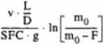
(SFC: specific fuel consumption, see cq. (31); t: time) which reduces mass (m) or weight dF* – dm. W« m g (39) but provides range (r) via speed (v) dr a v • dt (40) When introducing the other equations in (38), simple algebraic operations provide the differential Breguet-equation |
|
|||
|
|||
|
|||
|
|
||
|
|||
|
|||
|
|||
|
|||
|
|||
|
|||
|
|||
|
|
||

![]()
![]()
or
![]()
 (44)
(44)
Aerodynamics determine aerodynamic performance UD and so influence needed fuel F, but also provide requirements for structural layout and systems as well. Fuel, structures, engines, equipment and payload arc mass m0. Engines contribute to mass and provide its efficiency. which influences needed fuel. F and mass for fuel storage. The selected cruise speed
v or cruise Mach Af influences achievable L/D, engine efficiency Як or SFC, needed fuel F, and structure and equipment mass.
So. the Brcguctequation allows simple estimation of range, but it is still difficult to estimate improvements by singular technologies. But the Brcguctequation provides a rough estimation of range improvements, when only one parameter is changed, c. g. range improvement Дг provided by a pure aerodynamic improvement AL/D for the same aircraft (Яе[6] m©. F)- Now equation (43) gives
For fixed range, we can try to estimate the influences on fuel needed. (F). by the inverse Brcguct – equahon
But caution, now both m0 and F usually become strongly dependent on AL/D or ДЯе because better drag or engine cflicicnc) reduces fuel consumption F. and this reduces gross weight in*,. Therefore the inverse Brcguctequation usually calculates an aircraft whose performance is not exploited To exploit performance, the aircraft has to be resided. This cannot be calculated by a simple equation. As a first, very rough estimation, the unresized improvement for fuel consumption, calculated by the inverse Breguet-equation (46). has to be multiplied by the factor
1 ♦ (weight part under consideration) / m„ (47)
e. g for improvement of Яе‘ (I * F/m0). But remember. The Brcguctequation only calculates idealised cruise flight. Therefore it may only be used for estimation of tendencies in long range flight.
Small improvements in fuel consumption by individual technologies may be compared by the percentage of the individual improvement, multiplied by
weight part influenced by thie technology / payload. (48)
This is explained in Figure 12 by several examples for an Airbus A340-300B with an assumed 15** pure drag improvement or a 159 structure weight reduction; for all examples the maximum take-ofT weight (MTOW) was maintained by adding fuel or payload.
 |
figure 12 Improvement estimation
There are several technologies to improve a new SCT. In order to evaluate the importance of a technology, we must be able to estimate its influence on the realisation of an SCT. At present level of knowledge, there is a hierarchy of technologies from fulfillment of constraints over cruise performance to operations. The operations arc still at the last position, because we are on search for a technical solution. When a solution is found, operations will become more important, because they contribute strongly to cost performance
1.3.1 Technologies to fulfill constraints
Here technology estimation is possible by looking for the relevant physical principles. Influence on aircraft cruise performance and cost is indirect, but can be very strong and limiting.
The most important constraints for an SCT are:
Take-off:
• Field length:
The required thrust (i. e. engine si/c) is determined by weight (acceleration) and aerodynamic lift (span, w ing area, rotation angle) at lift-off (i. e. minimum airspeed).
Take-off field length is defined by runway length of the relevant airports to be used by SCT. Today about 11000 ft arc assumed
•Climb rate:
The required thrust is determined by Height and aerodynamic performance UD After take-off. a climb rate with one engine out must be maintained of
0.5% with gear extended and 3% with gear retracted.
Noise:
Noise is determined mainly by exhaust velocity of the jet engines (as long as the turboma – chincry »s well shielded by inlet and nozzle) and mass flow (i. c. thrust) (take-off thrust = mass flow exhaust velocity).
Stage 3 compliant low noise exhaust velocities are between 300 m/s (Airbus A340. well below stage 3 limits) and at most 400 m/s (47); for compliance, bypass ratio* of about 2 or comparable measures are required.
Low speed thrust is determined by field acceleration, by weight and drag during climb, and by drag during approach.
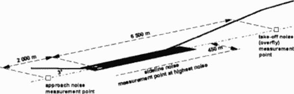
In the rules of ICAO, annex 16. chapter 3 and its derivations FAR 36. stage 3 or JAR etc. maximum noise allowed at take-off and landing is defined. Figure 11 shows the three points, where noise is measured Maximum noise levels allowed for the different points depend on aircraft weight and number of engines. Noise levels are measured in EPNdB. which is a time integral of the EPNL(dB) weighted noise. Additionally, if noise at one point is only a little more elevated (at most 2 dB). it may be compensated by lower noise at the other points, following some complicated weighting.
|
Figure 11 Noise Measurement Points Transonic acceleration: The highest wave drag values and the worst engine efficiency at nearly the same low supersonic speed may determine engine size. Best supersonic cruise performance docs not make any sense, if the supersonic aircraft is not able to reach supersonic speed |
Range:
Fuel amounts toa very high portion of gross weight (50% or even more). Therefore cruise efficiency determines range capability.
Airlines indicate, lhal a viable supersonic transport must be able to fly at least about 5 500 nm Many routes include segments over inhabited land, where only subsonic speeds are allowed.
Supersonic cruise:
Reduce aerodynamic drag (here by slenderness), reduce weight and improve supersonic engine efficiency (here via decreased by pass ratio), to meet range requirements.
Drag at supersonic cruise is dominated by wave drag, but friction drag and induced drag are important as well Drag has to be balanced by thrust
Subsonic cruise:
Improve subsonic engine efficiency (here via increased bypass ratio) and reduce aer – (dynamic drag (here mainly larger span); both reduce supersonic efficiency.
Drag at subsonic cruise is dominated by friction drag and induced drag, possibly vortex drag due to separation. Drag has to be balanced by thrust.
Controllability:
Provide control authority for ail disturbances either external (gusts, manocuvcrs) or internal (failure cases like inoperative engines, cabin pressure loss).
Emissions:
It seems that most important will be SOx-generation for us influence on the ozooclaycr.
NO*-gcncration is determined by peak temperatures which occur only at spot points in the burner, where stochiomctric conditions are met Low NO,-bumers reduce peak temperatures, but still maintain high mean temperatures.
Some of those constraining influences work against each other. For estimation of values compare subsonic aircraft of similar weight, c. g. B747. but pay attention to tlsc significant physical parameters.