Our heavyweight helicopter equal in the world does not have
In Rostov started production of the most load-lifting rotary-wing car The Russian holding «Helicopt[...]

Everything about aircrafts and helicopters. News and events in aviation worldwide. Civil, transportation, military helicopters and airplanes.

Everything about aircrafts and helicopters. News and events in aviation worldwide. Civil, transportation, military helicopters and airplanes.

Everything about aircrafts and helicopters. News and events in aviation worldwide. Civil, transportation, military helicopters and airplanes.

Everything about aircrafts and helicopters. News and events in aviation worldwide. Civil, transportation, military helicopters and airplanes.


SCTs arc very drag sensitive. Control surfaces and stabilizer, are minimized therefore Additionally. for slender configurations, the lever arms may become small. Consequently, unstable configurations arc selected, but if stability may be achieved via artificial stabilisation, control authority against failure cases (like engine failure) and gusts or manocuvers remains more critical. Many of the proposed configurations arc unable to provide the required control authority.
although – perhaps – they may achieve stability margins at the limit. Especially for some failure eases, like engine burst, missing redundancy of ailerons and elevens becomes critical for tailless configurations.
Long elastic fuselages (c. g. I0 > 90 m. 5 seat abreast) can easily provide loads of lg for crew, front and tail passengers by fuselage oscillations during ground roll, take-off rotation and in turbulence – additionally to gust loads. This not only seems inacccptablc. it really is inac – ccptablc. Only very stiff materials arc selected, weight seems to be at the limit; so a remedy seems only to be: wider, shorter fuselage with more drag and shorter range – or a completely different configuration, e g. an OFW.
In the cabin of an aircraft, pressure is always held at comfortable levels corresponding to about 8 000 ft. Tins allows for proper function of the human biological system. If a hole in the pressure hull of an aircraft develops, not only oxygen must be provided to the passengers, but the aircraft has to descent immediately to an acccptabcl altitude Even when aspirating pure oxygen, it cannot be transferred to the blood at pressure levels comparable to more than about 35 000 ft altitude; and sudden decompression will cause the blood to boil after a short time.
In ease of a pressure loss, therefore, the aircraft has to descend immediately and rapidly. During this steep descent, pressure levels in the cabin must never fall below cabin pressures of 40 (XX) ft; after at last two minutes a pressure altitude of at most 24 000 ft must be reached To descend fastly w ithout destruction of the aircraft, generation of drag is crucial (high altitude of about 50 000 ft must be reduced to 24 000 ft and simultaneously supersonic speed must be reduced to subsonic speed, both parts contributing almost the same part of required energy destruction).
There arc two main reasons for sudden decompression:
– engine burst:
probability of large holes can be reduced by suited positioning of the (most critical inner) enginc(s).
– "20 ft2 hole" (size may be a bit smaller for a narrow fuselage):
size of this hole is pure geometrical. It was introduced after DC-10 accidents (which lost doors) and is mainly a door size. There is no measure to reduce probability or increase safety against this hole. e g. by building double doors or a double hull; because geometry deliniuon is not influenced by it It cannot be seen now how this rule will be replaced by a physically based rule in the future.
At the high cruise levels of an SCT it is impossible lo maintain the requested pressure levels using conventional techniques. Really new technologies and intelligent solutions are needed
Presently, emissions are respected only for the certification of engines with respect to a typical landing and take-off (LTO) cycle which is related to the airport area pollution.
Cruise emissions still arc regarded to be (at least weakly) covered by LTO-rcquire- ments Future will show if this assumption remains valid or if new rules will develop
SCTs fly higher than subsonic aircraft; therefore their influence on the stratosphere and on the o/one layer is stronger. The stratosphere has not so much air exchange as the troposphere and therefore is more sensible. Interestingly, though, recent measurements – like the Airbus-program М02АЮ – indicate some strong global air exchange with the stratosphere.
Present rcscarch-bascd knowledge says that SCTs’ influence on stratosphere and ozone layer is low. even below measurement accuracy (± 1% steady state ozon change). SCTs below Mach 2 and subsonic aircraft mainly produce ozone, whereas SCTs beyond Mach 2 seem to destroy some ozone. Ozone production seems to change to ozone destruction at the upper limit of the tropopausc at about 18 km altitude (a mean value, higher at the equator, lower at the poles and in winter). In troposphere and tropopause the NO* of the aircraft exhausts generate ozone; but at least as important seems to be the strong affinity of NO* to the gaseous HC1 which is neutralized by NO* in the mean latitudes, transported to the poles, stored there in polar stratospheric clouds (PSC) and later on released there. If this holds, aircraft arc responsible for maintaining acceptable ozone levels in our mean latitudes by transferring some destruction to the poles
Often water vapor in the exhaust is cited as a contributor to the green house effect. It is not yet clear which contribution is more important: the green house effect which reflects earth infrared energy back to the earth, or the contrail shielding w hich inhibits sun energy from reaching the earth’s surface. In any case, the worldw ide water vapor emissions of ail aircraft have to
be multiplied by 104 (!) in order to get a first very small reaction in tlie model calculations. On the other hand, phenomena of atmospheric physics arc strongly nonlinear; so. today there exists not any useful indication on the importance of water vapor exhaust.
Altogether, scientific understanding and modelling of the stratosphere is not yet mature Prediction tests of proposed changes mostly don’t meet the data measured later-on. at least in the northern hemisphere with very complicated weather conditions. But a new SCT program will only be launched if certification and operation of many aircraft for many years can be based on reliable scientific predictions of the environmental implications
For noise ccnification of an aircraft (with a specified engine type), the aircraft has to fly precisely defined procedures to enable quantified noise measurements During those procedures, specific flight path propcnics arc prescribed (which often arc difficult to meet due to meteorological disturbances; this may require many test repetitions until the flight path requirements arc met). Pilot actions arc limited and must not include throttle or flap changes. Therefore, operational aircraft frequently are less noisy than certification flights.
In the future, standard procedures for flap and throttle scheduling may be accepted by the authorities for noise certification flights if those procedures arc always performed automatically by the flight management system not requiring any pilot action.
Presently, no noise rules exist for new SCTs. which means, that without a change or extension of existing noise rules, new SCTs cannot be certified. It is expected, that future SCTs must comply with the rules system FAR 36. stage 3 (perhaps modified) or even a future stage 4.
Certification of airports usually includes noise exposure levels (noise pressure, weighed by a human sensitivity filler including a weight for time of day. integrated over the noise exposure lime and the area) for the surroundings of the airports.
If the SCT will generate too much noise (e g. in climb phases not certification-related ). perhaps some airports will not accept SCTs although they can he certified according to the rules This may happen because the airport can loose its certification, if noise exposure levels nse too much, due to too much or too noisy traffic. Possibly the airports have to select the less noisy traffic to maintain their concession.
But airpon noise is not only related to aircraft (noise) performance, but also strongly to АТС (Air Traffic Control) procedures in the terminal area which often keep the aircraft for a longer time at low and noisy levels.
Before a new aircraft is allowed to transport passengers, it has to demonstrate its strength in a dynamic test. In this life cycle fatigue test, all important pans of the assembled test aircraft are loaded in a test ng with the load spectra which the aircraft has to expect in real airline operation. This includes the very rare maximum loads which arc only felt by very few aircraft. To provide a safety margin, the fatigue test must simulate twice the cycle number (and load events) before final certification. Aircraft in airline operation must never reach more than half the number of cycles which were tested in the dynamic lest rig.
For SCTs flying faster than Mach 1.8. this includes thermal fatigue testing and thermal cycling (like for Concorde). For SCTs flying at most Mach 1.8. the highest temperatures (about 80 *C> arc reached on ground, when the aircraft slays in the sun without any wind. So these temperatures are not different to existing aircraft and well within the limits of known materials Bui at Mach 2 mean temperatures at the aircraft skin arc about 105 ‘C. the hottest points at 125 ‘C. and at higher Mach numbers even higher.
Thermal fatigue testing has to simulate the stresses related to temperature gradients Temperature distribution and its gradients must therefore be simulated. Establishment of temperature gradients is a transient process which cannot be accelerated without changing (and mostly increasing» the gradients and stresses. Therefore cycling can only he accelerated for the equilibrium temperature limes: long ground stops and cruise after heating up all fuel.
New SCTs will he designed for a service of 60 000 flight hours and 20 000 cycles. When assuming that the simulation time saved by equilibrium flight roughly is as long as the ground simulation time for cooling down, this means fatigue testing of 120 000 h or 13.7 years! Today’s certification rules require certification to be completed within 12 years, although this may be altered for an SCT. Such long and complicated tests are very expensive. And faults detected during those tests may ground the whole fleet, at least the high cycle aircraft.
To save time and money it is proposed to develop a new technology for thermal fatigue certification: use partial simulation of representative subassembly pans with shoncr heating and cooling cycles. These partial simulations will he transposed into a total aircraft simulation required for certification which is based on a certified numerical simulation method.
A new SCT requires new materials to become viable – at least a new Concorde-type SCT; an Oblique Flying Wing (OFW) may possibly be using nowaday’s materials. But before new materials can be counted on in aircraft design, all relevant material properties must be well known And not only the matcnul properties itself, but also the technologies to design for them, work with them, form them, join them with other parts of the same material or with the other materials used
with them. When all this is known, we need the technologies and procedures to build and assemble large aircraft parts using these materials, which usually requires another set of manufacturing technologies And last not least, we need certification rules and procedures applied to these new materials
All these processes and the relevant data must be proven to be reliable and must be approved and certified by the authorities. This requires a long time, especially when fatigue related data are requested.
Before introducing a new material in aircraft design, it must be highly probable, that certification of the material and the related processes will be achieved timely. It’ this is not certain. a fall back solution must be developed (and possibly manufactured» in parallel! This is very expensive, consumes many resources and should be avoided whenever possible, but it can become necessary for risk minimisation in a light time schedule.
J. Mertens
Daimler-Benz Aerospace Airbus GmbH, Bremen, Germany
6.1 Introduction
Since certification of Concorde new certification standards were introduced including many new regulations to improve flight safety. Most of these standards arc to prevent severe accidents in the future which happened in the past (here: after Concorde’s certification). A new SCT has to fulfill these standards, although Concorde had none of these accidents. But accidents – although they sometimes occurred only for a specific aircraft type • have to be avoided for any (new) aircraft. Because of existing aircraft without typical accident types having demonstrated their reliability. they arc allowed to go on based on their old certification; although sometimes new rules prevent accident types which arc not connected to specific aircraft types – like c. g evacuation rules. Anyway. Concorde is allowed to fly based on its old certification, and hopefully in the future will fly ax safely as in the past. Bui a new SCT has lo fulfill updaicd rules like any other aircraft, and it has to be ’’just another aircraft" (75).
A new SCT. especially a Concorde-type SCT, has difficulties to fulfill take-off noise requirements. Any possibility to improve take-off performance and reduce noise must therefore be investigated.
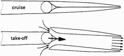
The engine companies have proposed several engine types for SCT. There are engines which provide so much high pressure air at take-off. that they can only apply full (thermal) power if a large amount of bleed air is used elsew here It is worth, therefore, to investigate ejee – lor flaps (Figure 34). mainly 10 increase thrust Problems lo be investigated are:
• What is the efficiency of the complex tubing and ejector flap system ?
• Docs the additional installation weight of the complex tubing and flap system offset the improvement of take-off performance?
• How complex and reliable will the system be?
• What is the noise of such an ejector system?
• Will exploitation of the ejector system for lift generation improve the design, w hen trim penalties and safety requirements arc respected?
|
|
Figure 34 Ejector Flaps
To estimate the pros and cons of such a system, probably an SCT optimized without ejector flaps must be compared with a completely independent optimum design which is adapted to the exploitation of the ejector flaps
5.8 Conclusion
A new SCT will only become reality, if many technologies are unproved or newly developed. Some of them are aerodynamic technologies, as mentioned above. But many of them require contributions by other disciplines or need interdisciplinary’ connection with others Both pure aerodynamics and interdisciplinary problems provide enough opportunities for many new intelligent contributions.
An SCT has a flight envelope strongly enlarged in comparison to subsonic transports. All new configurations, cither Concorde-like aircraft with thin w ings or an OFW. may provide some configuration deficiencies unknown for subsonic transports If the existing control devices cannot handle specific situations, or if the handling of those situations heavily penalizes those devices, then special control devices may have to be introduced for liandling these situations.
Examples:
If one engine stalls or an engine burst occurs at supersonic speed (OEI = One Engine Inoperative). strong lateral moments and rolling moments can establish. If handling of them penalizes rudder (and/or aileron) sizing, a special spoiler deflection on the other wing may compensate the occurring yaw. roll and pitching moments. Fine tuning is possible using the conventional controls
The oblique wing has superior aerodynamic performance, especially at low speeds This may inhibit an acceptable landing procedure with steep descent. Special devices can produce the requested drag w ithout inacceptablc introduction of pitching moments
Such devices strongly depend on the selected configuration. They are only recommended if they considerably reduce size, weight or complexity of the ahead) existing system. It is possible, that such devices case design of the control system layout, but complicating the system may occur as well.
Since the introduction of direct numerical optimisation, importance of inverse design methods has decreased. Sometimes inverse design is seen as a relict of old design techniques. But inverse design remains important. There arc cases, where the numerical effort of direct optimisation is still inaccepublc. Though this will change in future, there remain other cases: Inverse design allows to construct solutions for comparison with incomplete or defective solutions. E. g. using only partial inputs or other than geometry inputs, a geometry can he designed to he compared with the geometry used for a CFD-calculation Research is needed here, especially, if not only the classical inverse pressure design methods arc to be used, but also other input alternatives.