Our heavyweight helicopter equal in the world does not have
In Rostov started production of the most load-lifting rotary-wing car The Russian holding «Helicopt[...]

Everything about aircrafts and helicopters. News and events in aviation worldwide. Civil, transportation, military helicopters and airplanes.

Everything about aircrafts and helicopters. News and events in aviation worldwide. Civil, transportation, military helicopters and airplanes.

Everything about aircrafts and helicopters. News and events in aviation worldwide. Civil, transportation, military helicopters and airplanes.

Everything about aircrafts and helicopters. News and events in aviation worldwide. Civil, transportation, military helicopters and airplanes.


(Steady ) subsonic flow problems arc mainly of elliptic type in both the inviscid and viscous pans, which means that functions and all denvatives arc continuous. Only the invtscid Euler equations allow for discontinuities normal to the path (stream) line. Methods are on the development level as available for subsonic aircraft. Similar to subsonic aircraft technology, extremely complex flow separation is not yet really understood
5.3.2 Tasks
At take-off. it is necessary to
• improve lift
• maintain control
• improve L/D by reduction of drag; whereas at landing it is required to
• improve lift
• increase drag, possibly by drag control devices
• guarantee handling qualities, especially when using partially separated flow
The following tasks summarize the challenges of supersonic aerodynamic design:
• Provide aerodynamic data suited for interdisciplinary’ design optimisation. These data need not result from best achievable accuracy limits, but must be reliable within specified accuracy conditions for a wide range of configurations.
• Maximize aerodynamic performance (Lift/Drag * L/D) for given geometrical constraints: improve quality of aerodynamic tools to better reflect flow physics, balance wave drag, induced drag, friction drag (including lammansation concepts) for minimum overall drag.
• Determine the limits of special flow phenomena, like suction force, etc.
5.3 Low Speed Flight Regime
53.1 Dominating flow phenomena
At take-off and landing, low speed of the aircraft generates only small dynamic pressures. Generation of aerodynamic forces, therefore, requires high specific aerodynamic loading, up to the separation limits.
Low speed lift generation:
To improve lift, span can be increased (variable geometry aircraft like the OFW). camber can be increased by flaps and wing area by Fowler flaps Angle of attack can be increased (especially for highly swept wings) and engine air can be used directly for lift generation or for support of flap efficiency. Most SCT configurations have only limited possibilities to use flaps: the symmetric (Concorde-like) configurations have large wing areas, where flaps can contribute only marginally. For an arrow wing, inner wing flaps can be efficient, because they generate lift near to the center of gravity which reduces trim losses. For the OFW the pitching moments connected with camber or fowler flaps limit their application.
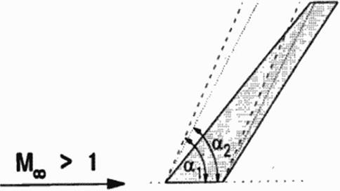
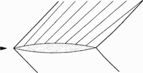
Of special importance arc leading edge flaps for symmetric SCT configurations which do not generate lift but reduce lift dependent drag Concorde generates additional lift using the lifting vortices generated by leading edge separation on highly swept wings Those vortices, on the other hand, produce high drag. For a new SCT it is intended to use those vortices • if used at all – only at lift-off and perhaps flare During climb, no vortices should separate at the leading edges to allow for lower climb drag. There are proposals to use droop flaps (Figure 31), or – proposed by Boeing – suction at the leading edge to delay leading edge vortex separation.
|
|
Figure 31 Drooped Leading Edge Separations:
At high aerodynamic loadings separation may occur. For landing, separation with separation drag is welcome, but separation must alway s be controlled; it must not suddenly alter the flight handling Leading edge separation must therefore he confined to highly swept leading edges, where the individual separation vortices arc til to the large lifting vortex. Trailing edge separation has to occur smoothly and at selected pans, like for subsonic aircraft Especially the OFW needs much drag for landing to inactivate its superior aerodynamics. Drag producing devices arc then requested which introduce only minor pitching moments
Controllability:
Due to the small dynamic pressure, control surfaces become less efficient. In addition, separation on control surfaces limits the achievable forces, separation on wing, fuselage and nacelles introduces additional disturbances.
Especially for highly swept trailing edges – like for arrow wings and OFW – the effcc- tivity of control surfaces is not >et completely undcrxood. Some additional research is needed here
In order to exploit the wing’s lift performance w ith droop leading edges and cambered or even fowlcrcd trailing edges, it is necessary to balance the aircraft by an additional control surface like a horizontal tail or canard
Performance:
At take-off. main emphasis is on good L/D to reduce thrust and noise. For landing, though, high drag is necessary to allow step descent and slowdow n, when the engines still run at flight idle with not too low thrust levels. On the other hand, enabling flare or allowing for go- around, drag must stay below some limits or must rapidly be reduced
Suction force:
Compared to lower flight speeds, the efficiency of leading edge suction in supersonic flow is reduced. Basically the effect should be correlated to the Mach number components normal to the leading edge, trailing edge, maximum thickness line etc. Following M. Mann and H. Carlson (67]. it should be correlated to free stream Mach number
Reasons for loss of suction force are:
• Low – pressures generate suction forces, but reduce density. This diminishes efficiency of suction forces, especially in combination with shock losses. These arc compressibility efTects which should be related to normal Mach numbers.
• Supersonic trailing edges inhibit circulation efficiency and so reduce suction force recovery. For supersonic leading edges suction force is lost.
• The flow field in the vicinity of the wing is governed by radiation processes. These processes arc not axactly modeled by numerical calculations: lincari/ed theory docs not течкі effects of local Mach number variations and therefore is unable to produce the correct radiation directions (characteristics). Most nonlinear methods respect for the local Mach numbers, but do not exactly model radiation; so numerical diffusion smears out radiation transport.
• Supersonic wings arc mainly designed for minimum wave drag. This leads to nearly conical flow situations. At higher Mach numbers with smaller Mach angles this introduces strong pressure gradients in spanwise direction, i. e. normal 10 the free stream direction. Boundary layer flow tends to follow local pressure gradients; so, boundary layer air will accumulaie in the low pressure valleys on the w ing and may modify the designed low wave drag pressure distributions. This effect should strongly depend on Reynolds number and might be stronger in low Reynolds wind tunnel tests than in free flight. This effect is mainly related to free stream Mach number
Radiation in CFD solutions:
Linearized theory does not model cfTccts from local Mach number variations. Usual CFD methods do respect these, but only marginally model radiation properties Numerical stability is achieved usually by addition of numerical viscosity. Without proper modelling of radiation properties, though, random contributions arc introduced into the solution or valid contributions arc assumed to be zero Upwind schemes should model radiation, but most upwind schemes are basically one-dimensional and cannot model radiation direction, like all the upwind schemes which only fulfill the eigenvalue sign; i. e. they approximate the radiation direction by an accuracy of up to ±90* Only CFD methods which are carefully based on the method of characteristics provide good radiation properties, but these methods usually arc not suited for universal CFD codes, especially for their rather inflexible handling of complicated geometries. A challenge remains to improve the tools for supersonic CFD
Physical drug contributions:
To improve the aerodynamic design of an aircraft, it is very helpful! to know the different contributors fo physical drag-
• Wave drag (radiated energy plus entropy generated by shocks)
• induced drag
• friction drag
• separation drag
For subsonic flow and linearized supersonic flow, methods exist largely based on far field balances, c. g. (68]. but for nonlinear supersonic flow the far field results are poor because of inexact radiation models. Also, surface integration accuracy is more difficult to achieve; only friction drag can easily be extracted.
Supersonic laminar flow:
This technology is still a big challenge, for both theoretical predictions and even more for experimental verification With aerodynamic efficiency improvements by successful lami – narisanon promising to be very high, a special book chapter is devoted to that field
Wait drag:
 |
In supersonic flow the disturbances are radiated away from the aircraft surface. Pressure balancing between aft and forward flow is impossible (Figure 26) or strongly limited for winged vehicles The result is wave drag, corresponding to the radiated energy (64).
Figure 26 Wave Drag
All energy is radiated along Mach lines. Pressure (and temperature) changes along the aircraft, resulting in a crossing over of Mach lines at some distance When Mach lines intersect, conflicting information arrives at this point which will he bridged by a shock. Eventually all wave drag energy is captured by shock energy
Circulation:
Disturbances can only propagate within the downstream Mach cone. This limits a build-up of circulation for finite wings (Figure 27). Leading edge flow can only influence the downstream part of the leading edge if the leading edge stays withtn the Mach cone (this is a so called subsonic leading edge). Information of the trailing edge can only reach other parts of the trailing edge to improve pressure recovery if the trailing edge is located within the Mach cone (subsonic trailing edge). The trailing edge can only improve a build-up of circulation if parts of the leading edge are within the trailing edge’s Mach cone; (his is only possible for low supersonic Mach numbers, high aspect ratio and high sweep angles.
|
|
Figure 27 Subsonic Leading and Trailing Kdges Kogan’s theorem:
Lift efficiency in subsonic flow is described by the downwind field behind the aircraft: si/e. strength and downwind distribution determine the induced drag (64|. Kogan (65J. [66J developed a similar theorem lor supersonic flow: Any point of the aircraft surface can only influence air in its downwind Mach conoid; any point on the aircraft surface can only he influenced by air in its upwind Mach conoid Kogan constructs the envelope of all downw ind Mach conoids originating at the aircraft leading edges, and all upwind Mach conoids originating at the aircraft trailing edges. The control surface defined by the intersection of those two envelopes contains all downwind information of the aircraft. Lift dependent drag of an aircraft is the smaller the larger this control surface area is, the smaller the mean downwind is and the less disturbed the downwind distribution is.
Interference drag:
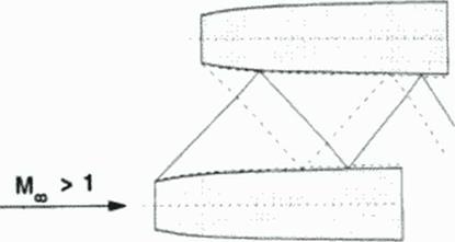
Shocks generated on the surface of engine nacelles (and other interfering parts) arc radiated to neighbouring parts like the wing, to other nacelles or the fuselage, where they arc reflected (Figure 28). Reflection conditions and drag is strongly influenced by shock-boundary layer interference. This requires reliable nonlinear calculation methods including viscous effects. Wind tunnel simulation must be able to simulate the viscous effects of high flight Reynolds numbers
|
Figure 28 Shock Reflection on Neighbouring Kngines Inlet flow: |
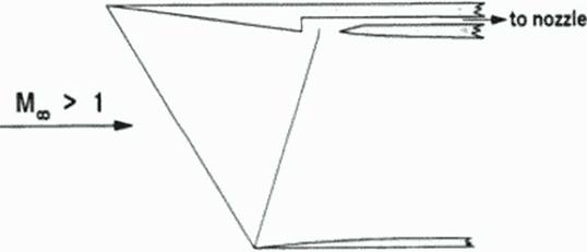
Jet engines work at purely subsonic speeds. The inlet of an SCT. therefore, has to decelerate incoming air from supersonic to subsonic velocities. This requires passing a shock system. To minimize shock losses, the air passes through several shocks (possibly including some iscntropic compression). Adequate mathematical models for the generation of shocks, control of shocks, shock position and shock reflection, including important viscous effects arc strongly nonlinear To enable stable flow conditions and engine operation, the inlet flow must be balanced with the nozzle flow; Concorde’s aerodynamically coupled nozzle and inlet control is still state of the art (Figure 29). Highly sophisticated numerical and w ind tunnel simulations are required and must be combined with the control system and engine operation
|
Figure 29 Inlet Flow. Concorde principle |
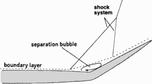
Hinge line shocks:
Al control surfaces, shocks at the hinge line region can provoke boundary layer separation bubbles strongly degrading flap efficiency and introducing vibrating airloads (Figure 30).
|
Figure 30 Shock-Boundary Layer Interference |
Mach cone and path (stream) line, sketched in Figure 23 are singular surfaces called ‘characteristic surfaces”; their generating lines are Mach lines or ‘’characteristics’*, hi viscid supersonic (or transient) flow is completely described by a set of partial differential equations (PDEs). valid only along characteristics, called "compatibility equations"; they do not contain any derivatives across the characteristic surfaces, but allow for undefined jumps in these derivatives 1581. (59J, {601, (61). {62). This means:
Any other set of PDEs describing supersonic (or transient ) flow contains derivative components normal to characteristic surfaces which are not defined by the PDEs’. Solutions of those equations may use invalid information or produce solutions containing random
pans. This may prohibit accurate or even useful solutions.
Inviscid supersonic (or transient) flow equations arc hyperbolic. They describe radiation problems. The FDEs itself allow for discontinuities in the derivatives of die variables (like velocity, pressure, entropy). If, for a given problem, the initial conditions do not contain discontinuities of the derivatives, discontinuities may evolve in the flow field. Furthermore, any solution to these equations (except for the tnvial identity solution, i. e. all derivatives are given everywhere as zero and remain zero) is composed only by discontinuous elementary solution parts, maybe for higher derivatives.
Л straightforward formulation for characteristic directions and compatibility equations was developed in the early 50ics by C. Heinz (63] at 1SL: Focusing on the essential normal direction, the number of equations used was reduced to the necessary minimum. This formulation is available in (61].
The above mentioned set of variables (velocity, pressure, entropy; total energy beeing dependent of pressure, velocity and entropy) is selected for decoupling of the variables in the compatibility equations. For other sets analogous formulations and discontinuities hold.
Viscous and heat conducting flow equations (Navier-Stokes equations) contain additional derivatives in all space directions without any preference. Those additional derivatives are of elliptical type; the resulting Navier-Stokes equations arc of mixed or parabolic type. Viscous and heat flux influence is limited to thin layers (boundary layer, shear layers, shocks) and separation regions.
Shocks can develop in the flowtield by steeping up of solutions and at boundaries, where sudden changes of boundary conditions occur. Shocks arc described by the Rankine – Hugoniot equations (58]. (59), (61] which arc derived by surface integration over a flat volume along the shock surface. Even the "inviscid" Rankine-Hugoniot equations contain viscous and heat fluxes across the shock surface. So the whole flowfield can be described by the inviscid equations, except boundary layer, shear layers and separation zones. In the free flow field, the discontinuous solution properties of the "inviscid" equations must be respected. Even when solving the Navier-Stokes equations for shocks, the thickness of a shock (less than 10 molecule free path length) is below numerical resolution; within this small layer the number of molecules is not sufficient to establish state variables as required for the continuum formulation of the Navier-Stokes equations. Therefore validity of solutions must be carefully checked.
In frequent case studies the capturing of shocks in numerical volutions is improved by selection of so called conservative variables which should be conserved when passing a shock. Caution is needed, though: In the Rankine-Hugoniot equations, basically not the variables are conserved, but their fluxes normal to the shock. For example, normal to a stationary shock not density p is conserved, but pvns. with ns the shock normal vector; only by chance, the conservative velocity pv (i. e. momentum) is the flux of p. On the other hand. v,. the velocity component parallel to the shock surface, is conserved across the shock, but not pv,.
J. Merten*
Daimler-Benz Aerospace Airbus GmbH, Bremen, Germany
5.1 Introduction
In the proceeding chapters on "Son of Concorde, a Technology Challenge" and "Aerodynamic Multipoint Design Challenge" it was explained, that a well balanced contribution of new technologies in all major disciplines is required for realisation of a new Supersonic Commercial Transport (SCT). One of these technologies – usually one of the most important for aircraft – is aerodynamics. Here, the required "pure" aerodynamic technologies are specified in more detail, according to our present know ledge. Increasing insight into the problems may change the balance of importance of the individual technologies and may require some more contributions. We must never confine our knowledge to the knowledge base of an expert at a given time, but must slay open for new insights
5.2 Supersonic Flight Regime
5.2.1 Physics of supersonic flow
In air. information of small disturbances propagates at the speed of sound. This information is transported by collisions between the molecules due to molecular thermal motion building up a bumping information chain at the speed of sound At subsonic speeds, this propagation speed is faster than flight speed. Therefore, the air molecules around an aircraft are informed about the motion of the aircraft by bumping neighbouring molecules. Changes of air velocity and pressure
are therefore smooth at subsonic speeds
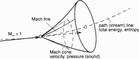
At supersonic flight speeds, the aircraft is faster than the information within the air. If we look at the disturbances produced by one small disturbance moving at supersonic speed in three succeeding seconds Figure 22. the disturbed field is inside of a cone, the Mach cone. Outside this cone, air is not yet informed about the disturbance and nobody can hear anything of it Important parameters are:
![]()
 |
|
M к v/a, M Mach number
Figure 22 Mach Cone
Information is spread only within the Mach cone But the transport of individual informations from neighbouring роїш to point is even more confined. Figure 23:
|
Figure 23 Propagation of Supersonic Perturbations |
• Information about small perturbations in pressure and velocity is transferred only along Mach-lmcs in the Mach cone.
• Information about small perturbations in total energy and entropy is transferred only along tike path line or stream line (stationary flow)
The formulations above reflect at first only invite id flow without thermal conductivity. Viscous fluxes and heal conduction exist normal to the Mach cone and path (stream) line. These additional fluxes become important along the path (stream) line; along the Mach cone their influence is very low.
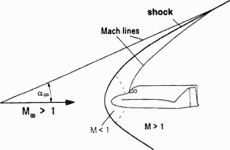
An aircraft flying ai supersonic speed is ши a small, but rather a strong perturbation. Because the air in front of the aircraft cannot be informed about the coming perturbation, smooth reaction is impossible. Instead, the air reacts instantaneously on this strong perturbation and adapts with a strong reaction to this situation: Within some free path lengths of the molecules (about 3 to 7) the airflow changes its mean velocity direction to follow the aircraft s surface. This sudden reaction not only requires a rapid flow change at the aircrafts surface, but also is radiated into the flow field. Figure 24
Air can transport information in smooth regions of the flow field only at the speed of sound. i. C. inside the Mach cone This requires that
• the Mach angle in from of the shock is smaller than the shock angle (otherwise a shock would not be needed, because smooth information would be possible);
• the Mach angle behind the shock is larger than the shock angle, because otherwise no information would be available to build up a shuck.
Speed of sound, a. only depends on temperature T:
a = у RT (63)
у: adiabatic exponent (ratio of specific heats)
R : special gas constant for air
The shock moves at supersonic speed (in normal direction to the shock surface) with respect to the air in front of the shock By passing the shock, air temperature (and speed of sound) increases to such an amount that the shock moves only at subsonic speed relative to the air behind the shock Behind strong shocks with high shock angles, the flow velocity is subsonic (relative to the aircraft), whereas for weak shocks with smaller shock angles the flow remains supersonic and only the component normal to the shock becomes subsonic. Figure 24.
|
Figure 24 Strong Perturbations |
Shock energy remains in the shock surface and is radiated only along the shock surface. Furthermore, by conflicting information from the Mach cones in front and aft the shock, new energy is radiated into the shock. Shock strength in larger distance from the aircraft therefore only very slowly decays.
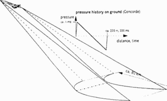
An SCT flying at about 16 000 m altitude produces a strong shock on the ground, the sonic boom Figure 25. Usually, the pressure history of the sonic boom shows two shocks: a front shock, a rear shock, and in between a nearly linear decrease of pressure, the so called N – wave. All information of wines with higher temperature concentrate at the front shock; all other informations of the regions with decreasing temperatures are collected by the rear shock. So the stable N-wave builds up and can be heard as a double bang on the ground. It is possible to design pressure distributions around the aircraft which do not steepen up to the pure N-wave. but those pressure distributions are not stable Only minor changes in temperature distribution of the air (weather conditions varying substantially in real atmosphere) or flight conditions
(Mach number; lift coefficient) destroy any carefully tuned pressure distribution and an N-wavc becomes dominant.
|
Figure 25 Sonic Boom |
The sonic boom is always to be heard when an aircraft passes flying faster than speed of sound. The bang is the stronger tlie heavier and shorter the aircraft is. and the lower it flies. The boom carpet has a limited lateral dimension of about HO km (as the Concorde), because higher speed of sound (temperature) at low altitudes produces cutinction of disturbances This lateral carpet size strongly depends on weather (temperature distribution) and speed of the aircraft with respect to the ground. Boom strength usually is strongest about the middle of the carpet; at the side of the boom carpet, noise is lower and softer Outside the cut-off distance no bang can be heard, but – if any – only the usual aircraft noise, like a grumble.
Contradicting requirements arc daily life for an engineer. But for a conventional SCT these four requirements really pose a design trap, mainly:
• high supersonic cruise performance requires
• a slender configuration with
subsonic leading edges (i. e. limited span) or very thin wings with leading edge flaps or variable geometry low engine diameters.
• low take-off noise requires
• large span with
round leading edges or leading edge flaps and large engine diameters.
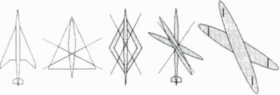
At DA a screening of several promising configurations was performed, see Figure 21:
|
Figure 21 Search for a Viable Configuration |
Remaining configurations were the conventional symmetric wing-body configuration at the left end. and the oblique flying wing (OFWj at the right end
The blended wmg-body lost for its poor slenderness. The optimizer simply concentrated the payload more and more at the center and spent more length for slenderness. So this configuration automatically transformed into the symmetrical wing-body.
The joined wing configuration has only limited span, does not provide enough fuel volume, does not provide space for an undercarriage and is structurally difficult, especially due to buckling.
The oblique wing-body combination is only interesting for rather small aircraft at low- supersonic speeds (57).
The extremely different aerodynamic requirements seem to prohibit a solution for the conventional symmetric wing-body, at least for large aircraft and long range Only limit performance of all disciplines’ technologies may reach the limit of viability. (Besides aerodynamics. severe pniblcms arc e g. weight, flutter, engines, long flexible fuselage, undercarriage» But this configuration has its merits for a smaller aircraft and shorter range, c. g. a 200 passenger transatlantic aircraft
The OFW is limited to large passenger aircraft, because profile height must be about
2.5 m or more. Therefore it is suited for SCTs with more than 250 passengers and for subsonic – aircraft with more than 400 passengers. The OFW provides variable geometry (aerodynamic – span) without large moving parts, and best supersonic performance It provides solutions to all the known problems of other configurations, like weight, noise, flutter, undercarriage, structural flexibility. In contrast it needs drag producing devices with controllable pitching moments to allow for a sufficiently steep descent and a short flare at touch down. Like with anything new there is still room for many new problems Also, the interfaces between the individual disciplines are strongly different from conventional (subsonic) aircraft.
Both a conventional solution at design limits or an unconventional OFW-solution pose a strong challenge for aerodynamics and the other disciplines The goal will only be met by new approaches using and further improving the techniques of Multidisciplinary Design Optimization (MDO).
Because both solutions require many new. unapproved technologies, flying technology demonstrators arc required in preparation of civil passenger traffic.
A supersonic jet is to cruise at supersonic speeds. But to reach supersonic speeds, it has to accelerate from take-off to the supersonic cruise speed But in between there is a speed regime with maximum wave drag and minimum engine performance which may determine engine size. This critical speed is the transonic acceleration point at low supersonic speed (about Mach 1.1).
Because wave drag is at its maximum, it dominates drag and (for rough estimations) the other pans may be omitted. So cqs. (49) or (50) become:
CD • 128 V2/(kSI*) ♦ KL • 02SCJ/(2ji/2) (59)
or in physical units
D = Kv2SV2/{nSI40)q + KLV2W2/{2nql2) (60)
where the first term for volume wave drag is dominant.
At Mach 2 the Mach-angle is 30*. at Mach 1.2 about 60’ and at Mach l just 90*. This
means, tliat at Mach 1 all disturbances produced by the aircraft arc radiated in a plane normal to the flight path and so stay in the relative position to the plane, at least when neglecting the local Mach number variations. (But these local Mach number variations arc the reason, that stationary or very slowly accelerated flight at Mach 1 is possible).
To minimize transonic wave drag, the configuration must be slender w ith a smooth variation of the total aircraft’s cross section area distribution These cross sections must include the variations of the engine s stream tubes For the large Mach angles of about 90*. changes of cross sectional area must be balanced in a very short streamwisc distance; but due to the nearly stationary propagation, the area distribution within each cross section is not so important. This may lead to so called "Coke-bottle" fuselages which balance (strong) variations of wing, tailplanc, engine areas by fuselage area changes.
To enable low wave drag at transonic and supersonic cruise speed, smooth area variations of all aircraft parts arc recommended.
It is easy to design a perfect supersonic or hypersonic aircraft which will not be able to accelerate to supersonic speeds. This was demonstrated several times in the past! And Concorde needs its fuel gulling afterburners to overcome this drag during a very slow ly accelerated part of the flight. If Concorde docs not sucecd in the first attempt to accelerate to supersonic speeds for a transatlantic flight, it has to return for refuelling!
No aircraft can fly without take-off and landing Therefore low-speed performance is crucial for the aircraft’s viability. Low speed performance determines the required thrust dunng take-off and landing, and so strongly influences airport noise. For future SCT. take off noise is the most difficult requirement! And a viable SCT must be even quieter than what is required today by certification authorities (stage 3). since many airports do not accept noisy climbing aircraft which
comply to stage 3. They have to respect the concerns of the sourrounding communities and have to restrict noisy aircraft in order to maintain their airport certification
At low speeds, high lift or high angles of attack arc required. Wave drag docs not exist, friction drag is nearly constant, so induced drag (and separation drag) dominates. This leaves only the last term in eqs. (49) or (50).
CD = AT, SCj/(Kfe:) (57)
or in physical units
D = KrW2/(nqb2) (58)
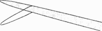
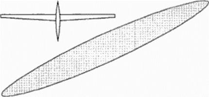
To minimize induced drag, we need a large span. This can be seen at high performance low speed planes like gliders, sec Figure 18. Sweep does ти help for drag, but special configurations (like the OFW) need it for stability and control For SCTs. the variable geometry of the OFW helps for take-off drag minimization. But it also reduces drag at low landing speeds; therefore an OFW needs additional pitching moment free devices to produce drag for landing. •
|
Figure 18 Low Speed Planes Additionally we must avoid separation: |
itself. This reduced lifting span increases drastically the induced drag. Figure 19. And Concorde needs its noisy afterburners to overcome this drag dunng take off.
• A new SCT has to avoid leading edge separation dunng climb to enable low noise proce durcs.
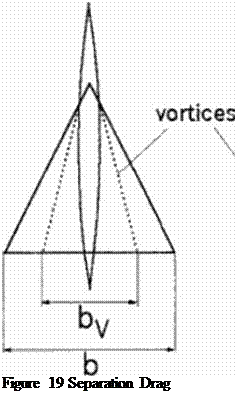 b: span for linear (potential) lift
byispan for additional vortex lift
 |
by
b
Figure 20 shows a design exercise for a new "Concordc-likc" SCT (for 250 passengers. 5 (XX) nm): Reference is a DA-dcsign (DA: Daimler-Benz Aerospace Airbus» of an aircraft which is optinu/ed just to meet stage 3. But because noise prediction is not very precise, the influence of aircraft noise on aircraft weight (MTOW) was investigated. Each square represents an optimized aircraft producing either more calculated noise than stage 3 (+ 0.5. to +9 dB) or less calculated noise (-0.5 dB) Weight strongly increases for lower noise, and just for – I dB no solution was found. It has to be respected, that noise measurement at certification has a scatter of nearly 2 dB. calculated noise prediction about 3 dB and weight prediction has its scatter also. This means that our design is still more than marginal!

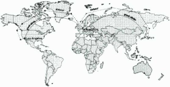
Because an SCT generates an annoying sonic boom as long as it flies faster than the speed of sound, supersonic operation will be limited to uninhabited areas, i. c. mainly over sea. Over populated areas SCTs have to cruise at subsonic speeds. But many important airports like Chicago. Atlanta, Denver. Frankfurt etc. arc far away from sea and many routes contain an important part of flight over populated land Therefore routings over uninhabited areas arc preferred, even at slightly increasing distances, but large subsonic cruise legs remain, Figure 16 It is estimated, that
an SCT must be able to cruise subsonically during one fourth to one third of the whole distance.
|
Figure 16 Supersonic Detour Routing |
Therefore a new SCT must provide good transonic (i. e. high subsonic) cruise performance. in contrast to Concorde’s poor subsonic performance, In addition to engines which provide good subsonic efficiency, aerodynamic design must provide this performance.
At high subsonic (transonic) cruise, good performance is achieved without significant contribution of wave drag. i. e. just below drag rise. So. in the drag composition of eqs. (49) and (50) the two wave drag terms can be omitted:
Cp = A/S •Cf + Kr SC2L/(Kb2) (55)
or in physical units
D = ACfq + К і • W2(Jt<//>2) (56)
Here mainly the sum of friction and induced drag has to be minimized and to be balanced with the other design requirements
The terms for fnction and induced drag arc described in chapter 2 after eqs. (49) and (50). Because here the flight is subsonic, supersonic leading edges do not exist. But optimum angle of attack is higher than at supersonic cruise. Therefore flow at relatively sharp or even really wedge-sharp leading edges may separate, producing high vortex drag which has to be avoided by suited leading edge flap deflections
To minimize high subsonic drag, we have to
minimize drag components by to optimizing geometry components:
friction drag surface. Cf (laminanzation)
induced drag span resp aspect ratio, and avoid separation
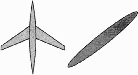
Therefore subsonic airliners have highly loaded high aspect ratio wings, sec Figure 17. This requirement contrasts to the supersonic cruise requirements. Here length I or l0 ts only required to delay the drag nsc Mach number, and for flight stability and control. The best solution would be a variable geometry, which was proposed by Boeing for the first US-SST. But the high weight of large movable pans prevented such a solution. In contrast, the Oblique Flying Wing (OFW) (56] provides variable geometry without large moving pans; therefore it is the bet[7] ter solution.
|
|
Figure 17 Transonic Cruise Aircraft