Category Principles of Helicopter Aerodynamics Second Edition

Torsional Damping

As mentioned previously, the highly nonlinear airloads obtained by operating the rotor in proximity to retreating blade stall can introduce aeroeiastic stability problems. One problem is called stall flutter, and this occurs when negative aerodynamic damping changes an otherwise stable aeroeiastic blade mode into a divergent or high amplitude limit cycle oscillation. The problem is particularly important for the torsion mode. A torsional damping factor, D. F. or Cw can be defined by the line integral

Torsional Damping(9.1)

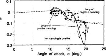
which is positive when it corresponds to a counterclockwise loop in the Cm versus a curve – see Carta (1967). If the torsional damping is negative, this would tend to promote an aeroeiastic divergence or flutter situation.

The progressive change from positive to reduced or negative torsional damping (for a given amplitude and reduced frequency of oscillation) is apparent as the mean AoA is increased into dynamic stall, as previously illustrated by the results shown in Fig. 9.4. It has been shown that the onset of light dynamic stall introduces a second clockwise loop of negative damping so that the pitching moment curve now looks like a figure eight. This second loop then grows in size with increasing mean AoA. Further penetration into dynamic stall produces a moment break that is now early enough in the oscillation cycle that the peak nose-down moment occurs while the AoA is still increasing. This introduces another new loop in the counterclockwise (positive) sense. More positive torsional damping is recovered when deep stall penetration occurs. Increasing the reduced frequency can act to delay the onset of stall to a higher AoA and can suppress the amount of flow separation, thereby reducing the negative damping, as shown previously by means of Fig. 9.5.

The aerodynamic torsional damping of an airfoil in the dynamic stall regime is a very difficult quantity to predict. While the various semi-empirical dynamic stall models appear

Torsional Damping

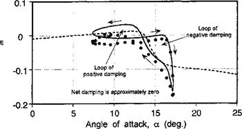
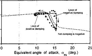
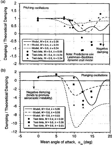
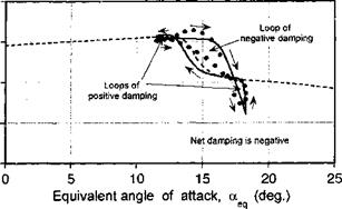
Figure 9.10 Comparison of predicted and measured torsional aerodynamic damping through conditions leading to dynamic stall for: (a) pitch oscillations and (b) plunge oscillations.

to give good predictions of the net forces and pitching moments, they do not always give good estimates of torsional aerodynamic damping. Because damping is an integrated quan­tity, the combination of conditions that determine dynamic stall onset and phasing of the center of pressure movement during vortex shedding must be determined very accurately. Measurements of the overall torsional damping trend versus mean AoA, am, is shown in Fig. 9.10, for both pitch and plunge forcing. Predictions were made using the Leishman – Beddoes dynamic stall model. The damping is normalized by the theoretical damping as given by the classical incompressible flow unsteady aerodynamic theory. Using the results in Chapter 8, then for pitching oscillations

Cm = 2^2 (nVba + ^k Qfc – i) aelcot = Cm sin (cot + ф), (9.2)

where

Подпись:Подпись: (9.4)Cm – 1 + ^k2 and Ф = sin 1 ) .

Substituting this expression into Eq. 9.1 gives

Cw — TtkaJ 1 4—— k2,

64

Torsional Damping Подпись: (9.5)

where aeq is the equivalent AoA (as defined in Eq. 8.182). By a similar process, the theo­retical torsional damping for plunging motion is found to be

The results in Fig. 9.10 show that in fully attached flow the torsional damping for an airfoil undergoing pitching motion is approximately twice that for equivalent plunging motion. This is because of the effects of pitch rate contributions to the noncirculatory pitching moment, which causes the area contained within the moment loop to be greater for a pitching airfoil than for a plunging airfoil under the same equivalent time-history of AoA forcing. This result is also seen in the experimental measurements (see Figs. 8.32 and 8.33).

The explanation for the observed behavior of the torsional damping can be deduced from Figure 9.4, where it has been shown that for higher mean AoA the pitching moment develops into two loops at dynamic stall onset, with a decrease in torsional damping. With further increase in mean AoA, the second loop increases in size and the net damping during the cycle rapidly decreases. Figure 9.10 shows that for both the pitch and plunge cases very low or negative damping is obtained at dynamic stall onset. At some point, just after stall onset, the mean AoA is sufficient such that significant negative damping reoccurs for the plunge oscillation. Although stall onset occurs at a lower equivalent AoA for an airfoil oscillating in pitch, the inherently lower damping for the plunging airfoil in attached flow means that the damping may well become negative at a lower mean AoA for conditions of oscillatory plunging. As the mean AoA is increased further, the damping increases again and ultimately becomes positive when fully separated flow conditions exist. See Carta (1967) for a detailed discussion of torsional damping under dynamic stall conditions.

Future Modeling Goals with Semi-Empirical Models

Overall, it can be seen from the results shown in Figs. 9.8 and 9.9 that the semi – empirical dynamic stall model provides fairly satisfactory predictions of the unsteady air­loads, for both pitching and plunging oscillations. Again, these results can only be considered as representative, and other semi-empirical models may provide better (or worse) results. None of the current models, however, can be considered as the last word on the problem, and it is likely that improved semi-empirical models of dynamic stall will continue to be developed for use in helicopter rotor applications.

The need to use some empirically identified coefficients in the types of dynamic stall models used in helicopter analyses is unavoidable. Empiricism, however, is not a negative concept, if suitably justified. Existing dynamic stall models have used from as many as

Future Modeling Goals with Semi-Empirical Models

Future Modeling Goals with Semi-Empirical Models

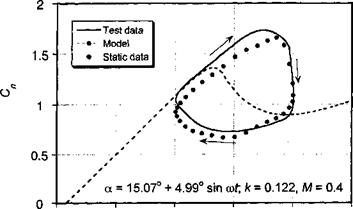
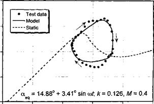
Figure 9.9 Comparison of model with measured airloads under pitch and plunge forcing, for NACA 23010 a == 15.07° + 4.99° sin cot, M = 0.4, к = 0.122; a = 14.88° + 3.41° sin cot, M = 0.4, к = 0.126. Data source: Liiva et al. (1968).


Future Modeling Goals with Semi-Empirical ModelsFuture Modeling Goals with Semi-Empirical Models

50 empirical coefficients to as few as four; these coefficients may also be a function of Reynolds number and/or Mach number. Many modeling efforts follow the relatively simple philosophy of enhancing prediction by using equations to amplify a pattern in the experi­mental results and so filtering out the less important physics and any noise. Yet complicated models always have a greater probability of modeling more and more of the unwanted noise and the uncertainties that are omnipresent in the experimental data. Therefore, one objective for the analyst should be to balance the complexity of the model by using a minimum num­ber of equations and coefficients, while maximizing the predictive accuracy and minimizing noise. One strategy toward this end is that all (most) of the identified coefficients should have a physical meaning and should be easily derived from either steady or unsteady airfoil measurements. Obviously, with a large number of coefficients it is hard to assign a physical significance to all of them. More important, however, with complex models the unique identification of the empirical coefficients becomes difficult and substantially increases the probability of unwanted noise. It is clear that most of the features of dynamic stall are a result of a few key causal factors, and so in principle dynamic stall can be modeled using relatively parsimonious models; the stall-delay model of Beddoes and the dynamic stall model of Johnson are good examples of this. In attempts to extend the generality of dy­namic stall models, say to more general airfoil shapes or to wider ranges of conditions, the complexity of the model must necessarily be increased and parameters added, and caution should always be exercised so as to retain the predictive success of the model.

Semi-Empirical Models of Dynamic Stall

Some typical engineering or semi-empirical models that have been used (or are currently being used) for modeling dynamic stall and that may be suitable for rotor airloads

predictions and rotor design analyses are as follows:

1. UTRC a, A, В Method: This is a resynthesis method, with the approach being described by Carta et al. (1970) and Bielawa (1975). The basis of this method is that in attached flow the airloads can be expressed in terms of the forcing parameters a, A — ac/2V, and В = otc2/AV2. In an attempt to isolate the dynamic contributions to the airloads, the static coefficients are subtracted from the total airloads. By appropriate crossplotting and interpolating for given instantaneous values of these parameters, the contributions to the dynamic airloads can be reconstructed and added to the static values. The method has met with some success, but large data tables must be generated for each airfoil and for each Mach number. A further development of this model that obviates the need for large tables is given by Bielawa (1975).

2. Boeing-Vertol “Gamma” Function Method: This model was initially developed by Gross & Harris (1969) and Gormont (1973). In the “gamma” function method, the influence of airfoil motion is determined by computing an effective AoA. First, the influence of plunging and pitching effects in attached flow is obtained by applying a “correction” to the AoA derived from Theodorsen’s theory at the appropriate reduced frequency of the forcing. From this, a second correction is applied from the instantaneous value of the “gamma” function. This gamma func­tion is obtained empirically as a function of Mach number from 2-D oscillating airfoil tests on the appropriate airfoil. The corrected AoA is then used to obtain values of the airloads from the static force and pitching moment curves. This has the effect of delaying the onset of stall to a higher AoA with increasing pitch rate, a result observed experimentally. The pitching moment is obtained from an em­pirically determined center of pressure function. Good predictions of the unsteady airloads are possible with this method [see Harris et al. (1970)], but the quantita­tive accuracy even for 2-D airfoils is deficient for conditions of stall onset or light dynamic stall. This model has been used in a comprehensive rotor analysis for the prediction of helicopter rotor airloads – see Gormont (1973).

3. Time-Delay Method: Beddoes (1976,1978) has developed a semi-empirical model for dynamic stall. Unlike the previously described resynthesis methods, the phi­losophy behind this method is to try to model, albeit still in a very simplified manner, the basic physics of the dynamic stall process itself. The method is based in the time domain. The behavior of the airloads in attached flow is obtained from Duhamel superposition using the Wagner indicial response function. Corrections are applied to this function to account for the effects of compressibility. Although scaling the Wagner function in this way is not rigorous, the results obtained ap­proximately replicate the increased lag in the unsteady loads resulting from com­pressibility effects. The key feature of this model is the use of two nondimensional time delays (based on semi-chords of airfoil travel). These time delays represent periods of nondimensional time that exist between identifiable dynamic stall flow states. The first time delay represents the delay in the onset of flow separation after the static stall angle has been exceeded and the time required for the initial separation to develop. The second time delay represents the time during which the leading edge vortex shedding process occurs. These time delays have been obtained from an analysis of many airfoil tests over a relatively wide range of Mach number. Similar studies have been done by Galbraith et al. (1986) but at lower Mach numbers. The results from the time-delay model have been shown to give good predictions of the unsteady airloads on 2-D airfoils. The method also requires relatively few empirical constants.

4. Gangwani’s Method: Gangwani (1982, 1984) has developed a synthesized airfoil method for the prediction of dynamic stall. This method is also based in the time domain. To model the airloads in attached flow, a “Mach-scaled” Wagner function with a finite-difference approximation to the Duhamel superposition integral is used, very much in the same manner as for the Beddoes time delay model. In the nonlinear part of the model, a series of equations with several empirical coefficients are used to represent the forces and pitching moments produced by the various dynamic stall events. These equations are based on the determination of “delayed” series of AoA, with the associated coefficients being derived from steady and unsteady airfoil data. Although a disadvantage with the method is the relatively large number of equations and empirical coefficients, nearly all of which are derived from oscillating airfoil data, credible predictions of the unsteady airloads have been demonstrated. The capabilities of this model have been independently evaluated by Reddy & Kaza (1987). One of the main difficulties with this method seems to be in predicting flow reattachment after dynamic stall.

5. Johnson’s Method: Johnson (1969, 1974) has developed a relatively parsimonious representation for incorporating dynamic stall effects on the sectional airloads. The experimental data of Ham & Garelick (1968) were used to develop the model in a form that could be used to correct the static stall lift and pitching moments as functions of pitch rate. Stall onset was represented by defining vortex shedding to occur just above the static stall AoA. It was assumed that vortex shedding produced increments in lift and nose-down moment that increased linearly to a peak value over a finite time, followed by a decay back to the static loads. Reasonable pre­dictions of the unsteady lift seem possible with this method, although the pitching moment predictions appear less pleasing.

6. Leishman-Beddoes’s Method: Leishman & Beddoes (1986,1989) have developed a model capable of representing the unsteady lift, pitching moment and drag char­acteristics of an airfoil undergoing dynamic stall. The model has been developed to overcome certain shortcomings of other unsteady aerodynamic models that were available up to about 1980 for use in rotor design and aeroelasticity analysis. The emphasis in this model is on a more complete physical representation of the overall unsteady aerodynamic problem, while still keeping the complexity of the analysis down to minimize computational overheads. The model was initially developed by Beddoes (1983) and Leishman & Beddoes (1986, 1989), with various refinements by Leishman (1989) and Tyler & Leishman (1992). Extensive validation of the model has been conducted with experimental measurements.

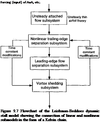
This model consists of three distinct subsystems arranged in the form of a Kelvin chain as shown in Fig. 9.7: 1. An attached flow model for the unsteady (linear) air­loads, 2. A separated flow model for the nonlinear airloads, and 3. A dynamic stall model for the leading edge vortex induced airloads. An important feature is that more rigorous representations of compressibility effects are included in the attached flow part of the model. These are represented using the indicial response functions for compressible flow (Section 8.15), along with linear superposition in the form of more accurate finite-difference approximations to the Duhamel’s integral. The treatment of nonlinear aerodynamic effects associated with separated flows are derived from Kirchhoff-Helmholtz theory, which can be used to relate

Output of unsteady airloads
Подпись: Forcing (input) of AoA, etc. Figure 9.7 Flowchart of the Leishman-Beddoes dynamic stall model showing the connection of linear and nonlinear submodels in the form of a Kelvin chain.

the airfoil lift to the AoA and the trailing edge separation point, a technique dis­cussed previously in Section 7.11.5 .In application, the experimental static lift stall characteristics are used with the Kirchhoff-Helmholtz model to define an effective separation point variation that can then be generalized empirically and used to re­construct the nonlinear airloads for any AoA. To represent the effects of dynamic stall, a third subsystem contains equations that emulates the dynamic effects of the accretion of vorticity into a concentrated leading edge vortex, the passage of this vortex across the upper surface of the airfoil, and its eventual convection downstream. The dynamic stall process begins when an equivalent leading edge pressure parameter reaches a Mach number dependent critical value indicative of leading edge or shock induced separation. To simulate the effects of the complex viscous dominated flow morphology during dynamic stall, the various time con­stants that describe the behavior of this third subsystem, and also of the trailing edge separation point subsystem, are modified in a logically determined sequence. One significant advantage of this method is that it uses relatively few empirical coefficients, with all but four at each Mach number being derived from static airfoil data. This model has also been adapted and modified by Pierce & Hansen (1995) for the class of airfoil sections used on wind turbines (see Section 13.9).

ONERA Method: This model describes the unsteady airfoil behavior in both at­tached flow and during dynamic stall using a set of nonlinear differential equations. The model was first described by Tran & Pitot (1981), Tran & Falchero (1981),

and McAlister et al. (1984), with various modifications by Peters (1985). A ver­sion of the ONERA model has been evaluated by Reddy & Kaza (1987). A later version of the model (the ONERA Edlin model) is documented by Pitot (1989). The coefficients in the equations of this model are determined by parameter iden­tification from experimental measurements on oscillating airfoils. Like several other models, including the Leishman-Beddoes model, the airloads are expressed as a sum of two components: a component associated with the linear (attached flow) behavior and an increment that represents a deviation from the linear value resulting from stall. The model requires 22 empirical coefficients for each Mach number. The later ONERA BH model, as documented by Truong (1993, 1996), requires 18 coefficients and also adapts the Kirchhoff-Helmholtz trailing edge flow separation scheme from the Leishman-Beddoes model.

Generally, reasonable predictions of the unsteady airloads are obtained with the ONERA model – see also Tan & Carr (1996) and Nguyen &~ Johnson (1998). However, like many of the models, the predictions are deficient for flow reattach­ment after dynamic stall. Based on the experimental studies of Green & Galbraith

(1995) , the modeling of dynamic flow reattachment requires as much care as for modeling dynamic flow separation, especially if accurate predictions of aerody­namic torsional damping are an objective. A apparent advantage of the ONERA method is that because all of the equations for the lift, drag, and pitching moment are written as differential equations, they are in a form that can be immediately useful for various types of aeroelastic analysis. However, the Leishman-Beddoes model has also been cast into differential equation form – see Leishman & Crouse (1989) and Leishman & Nguyen (1990). Furthermore, it would seem that the structure of some of the other semi-empirical dynamic stall models may also lend themselves to be cast into the same mathematical form, if required by the analyst.

8. Neural Network Methods: Recursive neural network (RNN) models are a class of nonlinear mathematical methods that have been used to model the effects of dynamic stall – see Faller & Schreck (1996). These models are developed in state – space form, where the state-matrix is developed recursively by “training” neural estimators. Like all semi-empirical models the method first requires access to a data set of measurements that can be used to train the model. In this postdiction (or calibration) phase the simulation error is progressively reduced to reproduce accurately the known input data. An assumption must be made as to the elements of the input forcing; generally the approach has met with reasonable success in reproducing the unsteady airloads under the assumption of simple inputs, such as a, a, and a. In some respects this approach is similar to the character of the UTRC model. However, for a helicopter rotor other elements of forcing are clearly involved (see Fig. 8.2) and training the model for more complicated interdependent inputs still requires further development. In some cases training data for certain modes of forcing may not be available, making RNN models less certain in terms of their ultimate predictive capability. Furthermore, RNN methods have not yet shown convincing results when reduced to simulate the “classical” problems m unsteady aerodynamics, such as idealized harmonic oscillations, nonuniform free – streams or vertical velocity fields, and indicial type problems. The large number of states also makes the RNN approach less attractive for many types of helicopter rotor applications, although the rapid advances in computer speeds makes this less of an issue than it might have been ten or more years ago.

9.5.2 Capabilities of Dynamic Stall Modeling

Based on the foregoing discussion, there are several different dynamic stall mod­els available to the helicopter rotor analyst, all of which represent, to an engineering level of approximation, the forces and pitching moments produced on an airfoil during dy­namic stall. Reddy & Kaza (1987) have compared and contrasted several of these models, from which the general quantitative capabilities and deficiencies were independently doc­umented. Used intelligently, it would seem that most of these models are adequate for use in a wide variety of rotor analyses. Much comes down to the confidence levels that

____ лп4-лиі:«ил4 4-і____________________________ u л_________ u~<-u л о гл „,лп

СШі ис cbuauiiMicu uuuugii іллісшішіі &шши, ииш аі а icvci аь wcu аа inaiuc uic rotor environment. Tan & Carr (1996) have presented a summary of results for a number of currently used semi-empirical dynamic stall models, as well as first-principles based CFD approaches to the dynamic stall problem. Results have been compared for both an oscillating 2-D-airfoil and an idealized 3-D problem in the form of an oscillating can­tilevered finite-wing (see Section 9.9). Again, it seems that if the semi-empirical models are used intelligently, very credible predictions of the integrated airloads can be obtained when compared to experimental measurements.

In the following discussion, predictions made by the Leishman-Beddoes model [see Leishman & Beddoes (1986, 1989)] will be used to show the general capabilities of the semi-empirical dynamic stall models. While it should be appreciated that some models might produce different or better results, the idea here is simply to illustrate the overall levels of performance that could be expected from these types of engineering models. It is obviously highly desirable to expose the models to different types of forcing, that is, not solely for oscillatory pitching as might have been used for formulation purposes. As mentioned previously, a large proportion of the aerodynamic changes m AoA that take place in the rotor environment come from blade flapping, which is equivalent to a plung­ing or heaving type of forcing at the blade element level. One underlying assumption that seems to be made in nearly all the various unsteady aerodynamic models described above is that the effects of blade motions and wake inflow variations can be adequately repre­sented by a lumped “equivalent” AoA – see Eq. 8.182. This proves an adequate assumption for fully attached flows, but Fukushima & Dadone (1977) and Ericsson & Reding (1983) have argued that more fundamental differences may exist in the dynamic stall airloads when different modes of motion are imposed (i. e., pitching versus plunging). This per­haps raises some questions about the capabilities of the various dynamic stall methods, in general, to predict accurately the unsteady airloads for completely arbitrary variations in AoA, pitch rate, and so on. However, while many 2-D oscillating airfoil experiments have been conducted to study dynamic stall, only a few experimental facilities can simulate both pitching and plunging oscillations or other combined motions so that this can be thor­oughly verified. This is mainly because plunge experiments are mechanically difficult to perform in a wind tunnel environment, especially over the wide rsnge of amplitudes und reduced frequencies that would be necessary to validate any theory. I. iiva et al. (1968) and Carta (1979) have measured oscillatory airloads under oscillatory pitch and plunging conditions. However, only the results obtained by Liiva et al. (1968) are for the ranges of Reynolds numbers and Mach numbers that are representative of those found on a helicopter rotor.

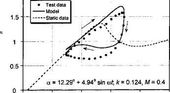
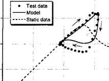
Figure 9.8 shows the normal force and pitching moment coefficient responses obtained for oscillatory pitching and plunging into dynamic stall. Notice that the general features of dynamic stall are evident here, with both sets of results showing a qualitative similarity for both types of forcing. The hysteresis loops predicted by the dynamic stall model are in good

2


a = 12.45°+ 3.14° sin cof; A: = 0.116, M = 0A

f eq


Semi-Empirical Models of Dynamic Stall

Figure 9.8 Comparison of model with measured airloads under oscillatory pitch and plunge forcing, for NACA 23010 a — 12.29° + 4.94° sincor, M = 0.4, к = 0.124; aeq = 12.45° + 3.14° sintyr, M — 0.4, к = 0.116. Data source: Liiva et al. (1968).


О. P p JT

<T> 3 ^ on О з


40


п> "a p о


r* ТІ


Semi-Empirical Models of Dynamic StallSemi-Empirical Models of Dynamic StallSemi-Empirical Models of Dynamic Stall

agreement with the experimental measurements – the only significant discrepancy is during the flow reattachment process. In both cases, stall onset is clearly postponed well above the static stall AoA, followed by leading edge vortex shedding. Both conditions suggest that an organized dynamic stall vortex is formed and convected downstream over the chord, although for the plunge case, the degree of stall penetration is slightly less.

Figure 9.9 shows dynamic stall loops for pitching and plunging oscillations performed at a higher mean AoA. These particular results are for conditions such that the minimum AoA is sufficiently high that the flow can only reattach to the airfoil surface during the latter part of the down stroke in AoA. The agreement of the model with the experimen­tal data is apain ve. rv pond for both nitr. h and піцпрр oscillations The nitchins moment response shows that stall onset is predicted a little early for pitch and later for plunge; in a practical sense these differences are small, however. The maximum nose-down pitching moment for the pitching airfoil is over-predicted, but it is predicted better for the plunging airfoil.

Carta (1979) has concluded that dynamic stall occurred on the airfoils during certain pitch oscillation cases but not in the corresponding plunge cases, even though the same equivalent AoA history was imposed. It appears that this behavior can, in part, be traced to the (inviscid) pressure distribution at the leading edge of the airfoil. For pitch oscillations the favorable “induced camber” effect discussed previously means that, in principle, the leading edge pressure conditions that delimit attached flow should be met at a lower equivalent AoA than for the plunge oscillations. Tyler & Leishman (1992) have confirmed that the stall onset behavior is related to the additional effect of pitch rate contribution to the unsteady airloads during pitch oscillations. Therefore, for “equivalent” conditions the degree of stall penetration and lift and pitching moment hysteresis should be somewhat greater for an equivalent pitch oscillation, confirming Carta’s observation.

Ericsson & Reding (1983, 1984) have put forward an alternative theory, postulating that the differences in the airloads seen between dynamic stall in oscillatory pitching and plunging is a result of two viscous phenomena: the “spilled” leading edge vortex but also another effect called the leading edge jet effect. While the leading edge vortex shedding phenomenon has been well documented experimentally, the role of the leading edge jet effect in the dynamic stall problem is much less clear. Ericsson & Reding suggested that this leading edge jet effect helps to delay the onset of leading edge separation on a pitching airfoil by producing a fuller boundary layer profile. The final result is, however, opposite to that inferred from both Liiva’s data and Carta’s data where, for nominally “equivalent” pitch/plunge forcing, a pitching airfoil is generally found to stall at a lower equivalent AoA.

. Modeling of Dynamic Stall

Mathematical models that attempt to predict the effects of dynamic stall currently range from relatively parsimonious empirical or semi-empirical models to sophisticated computational fluid dynamics (CFD) methods. Because dynamic stall is characterized by large recirculating, turbulent separated flow regimes, a proper CFD simulation can only be achieved by solving numerically the full Navier-Stokes equations with a suitable turbulence model. CFD methods have now begun to show some promise in predicting 2-D and 3-D dynamic stall events – see, for example, Srinivasan et al. (1993), Ekaterinaris et al. (1994),

and Spentzos et al. (2004) and also the discussion in Section 14.10.1. However, the quantita­tive predictions of the airloads are not yet satisfactory in the stalled regime and during flow reattachment and especially not at the Reynolds numbers and Mach numbers appropriate to helicopter rotors. In this regard, the accurate prediction of the transition from a laminar to turbulent boundary layer is a key issue. Furthermore, the computational resources for these CFD solutions are prohibitive other than for use as research tools, and for the foreseeable future more approximate models of dynamic stall will still have to be used in a variety of rotor airloads prediction problems, including rotor design work.

Some of the mathematical models of dynamic stall in current use are a form of resyn­thesis of the measured unsteady airloads, which are based on results from 2-D oscillating airfoils in wind tunnel experiments. Other so-called semi-empirical models of dynamic stall contain simplified representations of the essential physics using sets of linear and nonlinear equations for the lift, drag, and pitching moment. The nonlinear equations may have many empirical coefficients, which must be deduced (extracted) from unsteady airfoil measurements by parameter identification methods. However, the root of these models is usually based on classical unsteady thin-airfoil theory, as discussed in Chapter 8. The de­velopment of the nonlinear part of such models are more subjective and require skillful interpretation of experimental data. As a result, most of these models remain in a perpetual state of flux as the level of detail is refined and/or more experimental data become available for formulation and/or correlation purposes.

While semi-empirical models are usually adequate for most rotor design purposes, they often lack rigor and generality when applied to different airfoils and at different Mach numbers for which 2-D experimental measurements may not be available. Another major problem with some of these types of models is that a significant number of empirical co­efficients must be derived. Generally, a set of coefficients for the model must be derived for each and every airfoil, and also over the appropriate range of Mach numbers, assuming such measurements are available. In cases where experimental measurements are not avail­able, the models cannot be used with the same confidence levels to predict the nonlinear airloads. Other common limitations with these models include the accuracy with which the stall onset can be predicted, that is, the prediction of the combination of unsteady AoA and Mach number that produce the onset of dynamic leading edge flow separation. In these cases, computer coding of the model must be done with extreme care to ensure that logic or conditional branching in the algorithm does not cause nonphysical transients in the pre­dictions of the unsteady airloads, especially if large time (azimuth) steps are involved. This undesirable behavior may produce erroneous predictions of stall and aeroelastic behavior, which would be considered unacceptable for rotor design purposes.

Therefore, it is important for the analyst to build up a confidence level with any model selected for the design process. While a review of the literature will show a large number of experiments on dynamic stall that could be used for such purposes, the problem is usually that the full range of Reynolds numbers, Mach numbers, reduced frequencies, and, to some extent, airfoil shapes, cannot be studied in the same test facility or wind tunnel. Therefore, the same problems and uncertainties in data quality that were discussed in Section 7.9 in regard to comparing static airfoil characteristics also apply in the dynamic case.

Effects of Forcing Conditions on Dynamic Stall

Dynamic stall has been extensively studied experimentally, mostly using oscil­lating 2-D airfoils in wind tunnels. This simulates the quasi-periodic first harmonic AoA variations that are found on helicopter rotors during forward flight. The majority of the doc­umented experimental results are for airfoils oscillating in pitch, but there are some limited results available for plunging oscillations (vertical translation or heaving), as well as for constant angular rate (ramp) type motion. The former plunging experiments are useful in that pitch rate effects (i. e., a effects) can be isolated from the problem. The latter ramp tests are useful in that acceleration effects (i. e., a effects) can be eliminated, somewhat simplifying the understanding of the various effects produced by the airfoil kinematics on the unsteady airloads. However, both pitch and ramp experiments are difficult to perform, especially for the Mach numbers and effective reduced frequencies required to validate any mathematical model of dynamic stall.

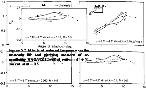
A few examples showing the variation of the unsteady airloads with variations in the oscillatory forcing parameters will now be described. With variations in parameters such as the amplitude of the AoA of the oscillation, the mean AoA, and the reduced frequency, the various dynamic stall events such as separation onset, leading edge vortex shedding, and flow reattachment all shift around the cycle to different values of AoA. This process results in significant quantitative changes in the unsteady airloads. Varying one parameter, while holding the others nominally constant can help to provide a better understanding of the physics of dynamic stall. To this end, Figs. 9.4 through 9.6 summarize the effect on the lift and pitching moment for increasing mean AoA, increasing reduced frequency, and increasing Mach number, respectively. The results are for a NACA 0012 airfoil taken from Wood

Effects of Forcing Conditions on Dynamic Stall

Angle of attack, a – deg. Angle of attack, a – deg.

Effects of Forcing Conditions on Dynamic Stall

Effects of Forcing Conditions on Dynamic Stall

Angle of attack, a – deg.

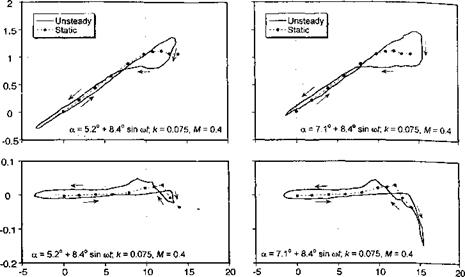
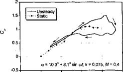
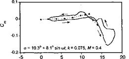
Figure 9.4 Effects of increasing mean AoA on the unsteady lift and pitching moment of an oscillating NACA 0012 airfoil at M = 0.4 with к — 0.075.

(1979), where the airloads were obtained by integrating pressures measured using miniature pressure transducers distributed around a section of a 2-D wing (see Fig. 7.30).

Figure 9.4 shows the effects of increasing mean AoA, while holding the amplitude of oscillation at approximately 8.4° and the reduced frequency at approximately 0.075. These results show the effects on the airloads as the flow state progresses from nominally attached conditions at the lowest mean angle, through “light” dynamic stall, and into “deep” dynamic stall for the highest mean angle. These “light” and “deep” dynamic stall descriptors were suggested by McCroskey et al. (1976, 1980) and Carr et al. (1977, 1978). For the lowest mean AoA of 5.2°, Fig. 9.4 shows a typical case of stall onset. This is when the combination of forcing conditions is just sufficient to cause some minor flow separation on the airfoil. Before this occurs, however, there is a delay in the onset of lift stall to a higher AoA and to a higher value of lift compared to the static case. The airloads then show some small deviations from the attached flow behavior (which would be almost pure elliptical loops) near the maximum AoA in the cycle as a result of the limited flow separation. As the AoA is reduced on the down stroke of the cycle the flow reattaches, as indicated by the return to the nominally elliptical shapes of the loop, but it will be noted that the AoA at which flow reattachment occurs is significantly below the static stall angle.

The second case shown in Fig. 9.4 is for a mean AoA of 7.1°, which is high enough to cause stronger leading edge vortex shedding and the creation of airloads that are more typical of “light” dynamic stall. In this case the maximum dynamic lift coefficient is about 0.4 higher than the static value, but the large nose-down pitching moment is of more significance. Also, because of the clockwise loop that is now introduced into the pitching moment curve (the curve now looks like a figure eight), this forcing condition represents a situation with significantly reduced torsional aerodynamic damping.[38] The third case shown in Fig. 9.4 is for a mean AoA of 10.3°, which is high enough such that the behavior would now be characterized as “strong” dynamic stall. Leading edge vortex shedding, again, contributes significantly to increased values of lift but gives a particularly large increase in the nose – down pitching moment. Because of the higher mean AoA, now a larger part of the oscillation cycle involves partly or fully separated flow, and so there are larger hysteresis effects. There is now another large counterclockwise loop introduced into the pitching moment curve, which gives a return to high torsional damping. Flow reattachment is delayed to a fairly low AoA during the down stroke motion. This indicates the relatively long time scales required for tne flow to reorganize after strong dynamic stall has occurred and so to allow conditions conducive for flow reattachment to occur.

Figure 9.5 shows the powerful effect of reduced frequency on the lift and pitching moment responses. In the first case, results are shown for a relatively low reduced frequency of 0.06, and for an AoA history that is just sufficient to produce stall onset or light dynamic stall. The other two cases are for the same nominal AoA forcing, but the reduced frequency has been increased to 0.1 and then to 0.15. Of particular note in these cases is that vortex shedding is delayed with increasing reduced frequency until it finally occurs at the maximum AoA achieved in the cycle. This delay in stall onset is, in part, because of the kinematic induced camber effect that is associated with pitch rate (Section 8.6). This effect progressively alleviates the leading edge pressure gradients for a given value of lift and thus delays the onset of flow separation to a higher AoA. At the same time, increasing the reduced frequency also delays the onset of flow reattachment, if flow separation occurs. In the third case, it is apparent that a high enough reduced frequency can be attained to prevent flow separation from being initiated at any point in the cycle. If the mean AoA were to be increased further, then a higher reduced frequency would be required to prevent flow separation.

Finally, Fig. 9.6 illustrates the effect on dynamic stall by increasing the Mach num­ber from 0.4 to 0.7, but under the same nominal forcing conditions, that is, for the same approximate AoA schedule and reduced frequency. It has been shown in Section 7.9.2 that the effects of compressibility manifest as a lower angle for attack for static stall on­set. These effects are also found in the dynamic regime, where for the same forcing the

Effects of Forcing Conditions on Dynamic Stall

degree of stall penetration and amount of hysteresis in the airloads are found to increase with increasing Mach number. Recall that dynamic stall onset is indicated by the break in the pitching moment. In the third case shown in Fig. 9.6, which is for a Mach number of 0.7, the dynamic stall onset involves the participation of a shock wave. This shock wave introduces a more complicated behavior in the center of pressure movement during the flow separation and reattachment process. Beddoes (1983) and Chandrasekhara & Carr (1990, 1994) give a detailed discussion of the role of shock waves in the dynamic stall process.

Dynamic Stall in the Rotor Environment

While much of what is known about dynamic stall has been obtained from ide­alized experiments on 2-D airfoils in wind tunnels, it is important to recognize that when

Dynamic Stall in the Rotor Environment
Подпись: Section lift, M C,

dynamic stall occurs on the rotor, it has a more 3-D character than previously described and may simultaneously occur over several radial and azimuthal parts of the rotor disk. Continued advances in miniature pressure transducer technology, high-speed data acquisi­tion and telemetry systems have enabled a more detailed understanding of dynamic stall

as it manifests on helicopters during actual flight. Isaacs & Harrison (1989) and Bousman

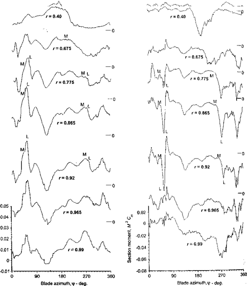
(1998) provide good in-flight documentation of the dynamic stall phenomenon on heli­copter blades. The results shown in Fig. 9.3 are adapted from Bousman (1998) and show the time histories of the lift and pitching moment at various radial stations on the blade of a UH-60 helicopter during a pull-up maneuver at /x « 0.3 and Ст/сг « 0.17. The results are presented in terms of the nondimensional quantities M2Cn and M2C, n, be­cause these quantities give a better quantitative measure of the local airloads produced on the rotor.

Using the unsteady chordwise pressures as an indicator, Bousman (1998) has identified three locations on the rotor disk for this flight condition that show the lift overshoots and large nose-down pitching moments that are characteristic features of dynamic stall. On Fig. 9.3 these are marked by points M (moment stall) and by points L (lift stall). Remember that dynamic lift stall always occurs after moment stall. At these particular flight conditions, it is apparent that dynamic stall encompasses relatively large areas of the rotor disk. In particular, note that the occurrence of dynamic stall causes large transients in the pitching moments, especially between r = 0.77 and r — 0.92 on the blade in the first quadrant of the disk and also on the retreating side near (r = 270°. Operating the rotor at thrusts or airspeeds beyond this flight condition will result in high structural loads and stresses that can quickly exceed the fatigue or endurance limits of the rotor and/or control system (see Fig. 6.8). Even though the rotor is usually able to operate with some amount of stall, the very rapid growth in the blade torsion and other structural loads because of dynamic stall is normally a limiting factor in the overall operational flight envelope of helicopters – see also Benson et al. (1973) and Stepniewski & Keys (1984).

Flow Morphology of Dynamic Stall

The effects of unsteady motion on unsteady airfoil behavior and dynamic flow separation have been recognized for many years, mainly through studies of oscillating airfoils in wind-tunnel experiments. As mentioned previously, for an increasing AoA it has been observed that the flow remains attached to the upper surface of an airfoil to an AoA much higher than that could be attained quasi-statically, giving a corresponding increase in maximum lift. Kramer (1932) was one of the first investigators to observe the phenomenon. The delay in the onset of flow separation under unsteady conditions is a result of three primary unsteady phenomena. First, during the conditions where the AoA is increasing with respect to time, the unsteadiness of the flow resulting from circulation that is shed into the wake at the trailing edge of the airfoil causes a reduction in the lift and adverse pressure gradients compared to the steady case at the same AoA. This “classical” effect has been described in Section 8.6. Second, by virtue of a kinematic induced camber effect, which has also been described in Section’8.6, a positive pitch rate further decreases the leading edge pressure and pressure gradients for a given value of lift. This can be considered a quasi-steady effect. Ericsson (1967), Carta (1971), Johnson & Ham (1972), Ericsson & Redding (1972), McCroskey (1973), and Beddoes (1978) have given a good summary of these basic effects from the perspective of unsteady airfoil theory. Third, in response to the external pressure gradients, there are also additional unsteady effects that occur within the boundary layer, including the existence of flow reversals in the absence of any significant flow separation – see McAlister & Carr (1979). These unsteady boundary layer effects have been quantitatively examined by Scruggs et al. (1974), Telionis (1975), and McCroskey (1975). Although the behavior of unsteady turbulent boundary layers is still not fully understood, the onset of flow separation on airfoils is generally found to be delayed by unsteady effects such as those associated with increasing pitch rate. Coupled with the aforementioned pressure gradient reductions, the resulting lag in the formation of boundary layer separation causes the onset of dynamic stall to be averted to a significantly higher AoA than would be obtained under quasi-steady conditions.

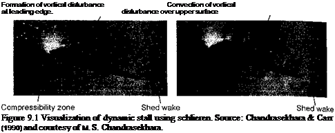
Flow Morphology of Dynamic StallUltimately, however, with increasing AoA, the high adverse pressure gradient that builds up near the leading edge under dynamic conditions causes flow separation to occur there. Experimental evidence suggests the formation of a free shear layer that forms just down­stream of the leading edge, which quickly rolls up and forms a vortical disturbance. This feature is now known to be a very characteristic aspect of dynamic stall and is shown in the flow visualization images in Fig. 9.1. Not long after it is formed, this vortical distur­bance leaves the leading edge region and begins to convect over the upper surface of the airfoil. This induces a pressure wave that sustains lift and produces airloads well in excess of those obtained under steady conditions at the same AoA. A qualitative understanding of this vortex shedding phenomenon was first given by Ham (1968) and McCroskey (1972a, b) and is reviewed by Beddoes (1979). A great number of subsequent experimental studies have provided a much more comprehensive physical understanding of the factors that deter­mine the onset of dynamic stall, including the important influence of compressibility – see Beddoes (1978, 1983), Lorber (1992), and Chandrasekhara & Carr (1990, 1994). How­ever, there have been fewer experimental studies of dynamic stall at the combinations of Reynolds numbers and Mach numbers that would be useful to the helicopter analyst. r ortunately, a few studies have been commissioned to study the effects of compressibility bn the quantitative effects of dynamic stall on airfoils operating at or near to full-scale rotor. Reynolds numbers – see, for example, Liiva et al. (1968) and Wood (1979). Generally, the results have shown that the qualitative features of the dynamic stall process remain similar
Подпись: (a) a = 15.9°

Подпись: Formation of vortical disturbance Convection of vortical at leading-edge. disturbance over upper surface Figure 9.1 Visualization of dynamic stall using schlieren. Source: Chandrasekhara & Carr (1990) and courtesy of M. S. Chandrasekhara.

(b)a = 17.1°

over a fairly wide range of Mach numbers and also under different types of forcing condi­tion (i. e., for pitching oscillations, plunging oscillations, and ramp or constant angular rate motions). Yet, the quantitative behavior of the airloads shows subtle variations with Mach number, especially for different airfoil shapes and under 3-D conditions. It is these more subtle aspects of the dynamic stall problem that make its accurate prediction difficult for the helicopter rotor analyst.

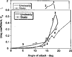
The various stages of the dynamic stall process are summarized schematically by means of Fig. 9.2. Stage 1 represents the delay in the onset of flow separation in response to a reduction in adverse pressure gradients produced by the kinematics of pitch rate (induced camber), the influence of the shed wake and the unsteady boundary layer response. Stage 2 of the dynamic stall process involves flow separation and the formation of a vortex disturbance that is cast-off from the leading edge region of the airfoil. This vortex disturbance provides additional lift on the airfoil so long as it stays over the upper surface. In some cases, primarily at low Mach numbers, the additional “lift overshoots” produced by this process may be between 50 and 100% higher than the static value of maximum lift. The effective lift-curve – slope may also increase during this process. These, often surprisingly large increments in lift, are also accompanied by significant increases in nose-down pitching moment, which results from an aft moving center of pressure as the vortex disturbance is swept downstream across the chord. The speed at which the vortex convects downstream has been documented to be between one third and one half of the free-stream velocity – see Beddoes (1976) and Galbraith et al. (1986). It will also be seen from Fig. 9.2, that the sudden “break” in the lift coefficient at the start of Stage 3 occurs at a higher AoA than that for the divergence in the pitching moment; that is, the pitching moment break (moment stall) occurs at the onset of vortex shedding (start of Stage 2), whereas the lift break (lift stall) occurs when the vortex passes into the wake (end of Stage 2 and start of Stage 3).

After the vortex disturbance passes the trailing edge of the airfoil and becomes entrained into the turbulent wake downstream of the airfoil, the flow on the upper surface progresses to a state of full separation. This is referred to as Stage 4 of the dynamic stall process: it is accompanied by a sudden loss of lift, a peak in the pressure drag and a maximum in nose-down pitching moment. In this flow state, the airloads are approximately the same as those found under steady conditions at the same AoA. Flow reattachment can take place if and when the AoA of the airfoil becomes low enough again. However, there is generally a significant lag in this process [see Green & Galbraith (1995)]. First, there is a

Flow Morphology of Dynamic Stall

Figure 9.2 Schematic showing the essential flow morphology and the unsteady airloads during the dynamic stall process on an oscillating 2-D airfoil. Adapted from Carr et al. (1977) and McCroskey et al. (1982).

general lag in the reorganization of the flow from the fully separated state until it becomes amenable to reattachment. Second, there is a lag because of the reverse kinematic “induced camber” effect on the leading edge pressure gradient by the negative pitch rate (see also Question 8.2). Therefore, full flow reattachment may not be obtained until the airfoil is well below its normal static stall angle, as denoted by Stage 5 in Fig. 9.2. In this particular case, it is apparent that the AoA falls to as low as 5° before the flow can be considered as fully attached. Because of these lags in the development of the various flow states, a large amount of hysteresis is present in all three components of the unsteady airloads. These hysteresis effects are the source of reduced aerodynamic damping, which as mentioned previously, can potentially lead to aeroelastic problems on the rotor.

Dynamic Stall

Fortunately, engineers and technologists do not wait until everything is completely understood before building and trying new devices. Even so, an improved understanding of fundamental unsteady fluid flow processes can serve to stimulate new innovations, as well as improvements in the performance, reliability, and costs of many existing machines. Therefore, research in unsteady fluid dynamics seems assured a lively future in modem industrial societies.

William J. McCroskey (1975)

9.1 Introduction

The phenomenon of dynamic stall has long been known to be a factor that limits helicopter performance. The problem of dynamic stall usually occurs on the rotor at high forward flight speeds or during maneuvers with high load factors and is accompanied by the onset of large torsional airloads and vibrations on the rotor blades – see, for example, Tarzanin (1972), McCroskey & Fisher (1972), McHugh (1978), Bousman (1998), and Isaacs & Harrison (1989). Whereas for a fixed-wing aircraft, stall occurs at low flight speeds, stall on a helicopter rotor will occur at relatively high airspeeds as the advancing and retreating blades begin to operate close to the limits where the flow can feasibly remain attached to the airfoil surfaces. As shown previously by Fig. 7.1, the advancing blade operates at low values of AoA but close to its shock induced flow separation boundary. The retreating blade operates at much lower Mach numbers but encounters very high values of AoA close to stall. Because of the time-varying blade element AoA resulting from blade flapping, cyclic pitch inputs, and wake inflow, the flow separation and stall ultimately occurs on a rotor in a very much more dynamic or time-dependent manner. This stall phenomenon is, therefore, is referred to as “dynamic stall.” Despite the fact that the static stall characteristics of airfoils have been discussed extensively in Chapter 7, the problem of flow separation and airfoil stall must now be reassessed from a nonsteady perspective.

Following the general definition given by McCroskey and colleagues (1976, 1982), dynamic stall will occur on any airfoil or other lifting surface when it is subjected to time – dependent pitching, plunging or vertical translation, or other type of nonsteady motion, that takes the effective AoA above its normal static stall angle. Under these circumstances, the physics of flow separation and the development of stall have been shown to be fundamentally different from the stall mechanism exhibited by the same airfoil under static (quasi-steady) conditions (i. e., where k = 0). Dynamic stall is, in part, distinguished by a delay in the onset of flow separation to a higher AoA than would occur statically. This initial delay in stall onset is obviously advantageous as far as the performance and operational flight envelope of a helicopter rotor is concerned. However, when dynamic flow separation does occur, it is found to be characterized by the shedding of a concentrated vortical disturbance from the leading edge region of the airfoil. As long as this vortex disturbance stays over the airfoil upper surface, it acts to enhance the lift being produced. Yet, the vortex flow pattern is not stable, and the vortex is quickly swept over the chord of the blade by the oncoming flow. This produces a rapid aft movement of the center of pressure, which results in large nose-down pitching moments on the blade section and an increase in torsional loads on the blades. This is the main adverse characteristic of dynamic stall that concerns the rotor analyst, for which the effects have proved difficult to predict.

As discussed by Beddoes (1979, 1983) and Wilby (1984, 1996, 1998), the consideration of dynamic stall in the rotor design process will more accurately define the operational and overall performance boundaries of the helicopter. Generally the rotor will be first designed so that the onset of high hlade loads, aeroelastie problems or limits in fUrrk+ performance are not limiting factors on the basis of linear and nonlinear quasi-steady aero­dynamic assumptions (i. e., using the blade element representations described in Chapter 7). Nonlinearities in the airloads associated with dynamic stall can introduce further effects that give rise to dangerously high blade stresses, vibrations, and control loads. One such nonlinear phenomena is called stall flutter.’ Because of the significant hysteresis in the airloads as functions of AoA that takes place during dynamic stall, and also because of the possibilities of lower aerodynamic damping, an otherwise stable elastic blade mode can be­come unstable if flow separation is present. Therefore, the onset of dynamic stall generally defines the overall lifting, propulsive, and aeroelastie performance limits of a helicopter rotor.

The accurate prediction of the combination of AoA and Mach number on the blade section that will produce dynamic stall onset, as well as the prediction of the subsequent effects of dynamic stall on rotor loads and performance, is not an easy task. The phenomenon of dynamic stall is not fully understood and is still the subject of much research on both experimental and numerical fronts — see Carr (1988). The very large number of publications on the phenomenon (see bibliography for this chapter) illustrates the importance of dynamic stall in the more complete aerodynamic and aeroelastie analysis of the helicopter rotor and the difficulties in both measuring and predicting the phenomenon. The complicated nonlinear physics of dynamic stall means that the behavior can only be completely modeled by means of numerical solutions to the Navier-Stokes equations (using computational fluid dynamics or CFD). This, like other CFD problems that involve unsteady, compressible, separated flows, the solution to dynamic stall problems is a formidable task that is not yet practical, but see the detailed discussion in Section 14.10.1. However, since the early 1990s, the rapid increase in computer resources has enabled considerable progress to be made in modeling dynamic stall by means of CFD approaches – see, for example, Srinivasan et al. (1993), Ekaterinaris et al. (1994), Landgrebe (1994), Barakos et al. (1998), and Spentzos et al. (2004). CFD methods will eventually prevail, but for the most part these methods are currently impractical for routine use in helicopter rotor analyses or design studies. For engineering analyses, the modeling of dynamic stall also remains a particularly challenging problem. To this end, a large number of semi-empirical models have been developed for use in helicopter rotor analysis and design codes. A brief discussion of some of these methods will be described in this chapter, along with a demonstration of their general capabilities in predicting dynamic stall induced airloads. While giving good results, these models are not strictly predictive tools and can really only be used confidently for conditions that are bounded by validation with experimental data. Such data, unfortunately, are not easy to obtain, requiring extensive wind tunnel testing on airfoils and wings, but remains fundamental to the success of such engineering models.

1 This is different from classical flutter, which involves fully attached flow.

Chapter Review

This chapter has described the key physical features of the unsteady aerodynamic effects found on airfoils operating under nominally attached flow conditions and away from stall. Unsteady aerodynamic effects have an important role in the prediction of the airloads and performance of helicopter rotors. The contributions of circulatory and noncirculatory effects to the unsteady airloads have been described, and their effects have been explained through the use of classical unsteady aerodynamic theories. These theories have their origin in thin-airfoil theory, with allowance for a shed vortical wake of nonzero strength down­stream of the airfoil. Of primary significance is that unsteady effects manifest as phase differences between the forcing function and the aerodynamic response; these are func­tions of the reduced frequency, the Mach number and the mode of forcing. While most of the classical unsteady aerodynamic theories are elegant in mathematical form, they are restricted to fully incompressible flows. This is an assumption that is hard to justify for helicopter problems, where both the local Mach numbers and effective reduced frequencies are generally high enough to render incompressible flow assumptions invalid, at least under the strictest terms. However, sometimes even some allowance for unsteady effects provides a better predictive capability than if quasi-steady flow alone is assumed.

Подпись: ForПодпись:flows no exact analytic solutions are available for unsteady airfoil problems, at least not over the entire time domain, and numerical solutions must be sought. However, the extension of the classical incompressible methods to subsonic compressible flows can be approached using many of the same fundamental principles as for incompressible flow, albeit using certain levels of approximation. It has been shown that compressibility effects generally manifest as increased phase lags between the forcing function and the unsteady aerodynamic response. For some transient problems, such as blade vortex interactions and unsteady trailing edge flap motions, the treatment of compressibility proves essential if the correct amplitude and phasing of the aerodynamic loads are to be predicted. Validation of the various methods have been conducted with experimental results. Unfortunately., many of the problems of interest are difficult to simulate experimentally, and recourse to indirect validation has been the only choice. However, the recent advent of nonlinear methods based on CFD solutions to the Euler or Navier-Stokes equations has provided a new standard that now helps define the limits of applicability of the classical theories.

The problem of understanding and predicting rotor noise continues to be a challenging one for the analyst. While much progress has been made, the significant reduction of heli­copter noise is an illusive goal. To this end, the accurate modeling of unsteady aerodynamic forces on the blades continues to be fundamental to the prediction of rotor noise. While the better use of CFD methods is often held out to be the answer, good acoustic results are still possible within the framework of linear unsteady aerodynamic theories, albeit with proper correction for compressibility effects. These types of models are also amenable for inclusion in comprehensive rotor analysis, such as those including rotor blade dynamics and aeroelastic response, and perhaps also flight dynamics simulations. Acoustic tools such as wave tracing also provide good insight into the acoustic directivity produced by BVI phenomena and can be used to augment FW-H or other solutions in terms of understanding

Methods of Rotor Noise Reduction

It will be clear that in the quest to reduce helicopter rotor noise not only does the rotor noise intensity and directivity need to be predicted accurately, but strategies need be devised to either reduce or defocus rotor noise. One approach is to first try to relate the far-field rotor noise levels to their source points on the rotor. This has been recognized by several authors, including Sim et al. (1995), Lowson (1996), and Strawn (1997). Therefore, at least in principle, it may be possible to modify the aerodynamics at specific source points on the rotor and change the propagated noise in a profitable way. This, however, is not an easy goal, and even if possible theoretically by means of calculations and analysis, much work will be needed to actually implement any such proposed system on a helicopter.

The use of higher harmonic cyclic blade pitch [see Brooks et al. (1991) and Yu et al.

(1994) ] and active trailing edge flaps [see Charles et al. (1994) and Dawson (1995)] have been suggested to modify the unsteady blade airloads and alter the intensity of propagated BVI noise. While some benefits have been realized on actual rotor tests, these approaches have been only “open-loop” processes and so require extensive mapping out of the combina­tions of conditions where significant noise reductions are actually obtained. These reduced noise flight conditions, unfortunately, often coincide with increases in vibration levels on the rotor, which will never be acceptable. Passive designs such as blade tip sweep and unequal blade spacing have also been proposed to dephase rotor noise sources [see Baeder (1997) and Sullivan et al. (2002)]. Operational techniques such as aircraft trajectory opti­mization or tip-path-plane AoA control proposed by Schmitz (1998) may offer such benefits in changing vortex/blade miss distances at the rotor. Validation of this approach, however, will require careful predictions of the rotor wake to understand the relative changes in the
wake to flight condition. However, to be successful any approach toward noise reduction still requires a better understanding of the nature and focusing characteristics of the critical sound sources generated by the rotor. The problem of rotor noise reduction continues to be a prime opportunity for future research in helicopter aeroacoustics – see Brentner (1997a, b) and Edwards & Cox (2002).