Category The Aerodynamic Design of Aircraft

Lifting wings at supersonic speeds

6.8 Consider now the design of lifting wings at supersonic speeds when the attachment lines lie along the leading edges, to extend the discussion in section 6.6 of the corresponding problem at subsonic speeds. The flow we have in mind is one where the bow shockwave is weak and attached to the pointed apex of the wing, and where the shockwave system at the trailing edge has no significant upstream influence and can be regarded simply as the first stage of the process by which freestream condi­tions are regained behind the wing. Viscous effects are confined to these shocks and to the boundary layer which may be assumed to remain attached to the surface forward of the trailing edge, at least at the design point. The disturbance velocities produced by the lifting wing may be assumed to be small compared with the velocity of the mainstream. The local load vanishes along the leading edges. The wing is almost planar and its shape, including the leading edges is smooth. The design Mach number is at once well above the transonic, mixed-flow, range and well below the hypersonic range, where the leading edges would be sonic or supersonic. There is thus no obstacle to the linearisation of the governing equations of motion and of the boundary condi­tions. These circumstances combine to make the situation suitable for the application of the linearised theory of supersonic flow past thin wings and of approximations to it – slender thin-wing theory and not-so-slender thin – wing theory may be adequate in many cases. Thus we discuss theories based on (6.50) or (6.52), as counterparts to those for thick wings in section 6.7.

For aerodynamically slender wings, the relation between the local downwash vz(x, y) and the local load i.(x, y) has already been given in (4.66) and the solution for flat wings in (4.67) to (4.69). For warped wings, the discussion in section 6.6 applies again, and the method of J Weber (1957) can be used.

There are several general methods based on linear thin-wing theory, notably by G J Hancock (1958), G M Roper (1959), and M Fdnain (1961). They use different, but equivalent, forms of the basic downwash equation which replaces (4.49) when the mainstream is supersonic. All involve the differentiation of functions which have to be calculated numerically. This tends to be inaccurate relative to the integration process, and it complicates the numerical analysis by the introduction of a further finite-difference approximation. These matters have been discussed in detail by J H В Smith et al. (1965), who show that these difficulties disappear completely if the order of the calculation can be inverted so that the differentiation operations are carried out

Lifting wings at supersonic speeds Подпись: I [f (Э2Лф _ 2 ЛЛ dx'dy' 2*V0 JJ Эу’2 Эх'2/ [(x - x')2 - Є2(у - y')2]i ’ Подпись: (6.72)

directly on the data and if these are specified analytically. Even if the data are given numerically, the difficulties are removed from the main cal­culation and arise in the initial stage of preparing the derivatives of the data. If the lift distribution vanishes at the leading edges of the wing like the square root of the distance from the edge, a convenient form of the down – wash integral is

where the integration is to be carried out over the Mach forecone, as defined by (6.54) and shown in Fig. 6.60. The discontinuity in the disturbance potential Дф(х, у) is related to the local loading £(x, y) by

£(x, y) = “ "ix дФ(х»У) » (6.73)

and the downwash is equal to the local slope of the mean surface of the wing, as before. The integration operations in (6.72) are conventional. The inte­grand has always a pair of square-root singularities at the ends of the inte­gration interval, whether these lie on the leading edges or the Mach lines.

At the four corners of the curvilinear quadrilateral formed by the leading edges and the Mach lines, these singularities coalesce and simple poles occur. They can be dealt with by classical methods. In the application to the design of the mean surface of a warped wing, it is no effective restriction to require that S,(x, y) or Дф(х, у) be expressed analytically and the differen­tiations in equation (6.72) can then be carried out in closed form. On the other hand, it is important to choose suitable expressions for the loadings to be physically realistic and to correspond to low values of the lift – dependent drag. To express the behaviour at the leading edges, given by у = ±s(x) , in a natural form, the coordinate n = y/s(x) must be introduced. Smith et al. (1965) represented the loading by the product of (1 – n^)i and a polynomial in f whose coefficients are polynomials in x, and this has been proved to lead to an efficient and flexible design method.

Wings with curved subsonic leading edges are not amenable to exact treatment by linear theory, but useful approximations can be provided by the not-so – slender wing theory of Mac C Adams and W R Sears (1953), which has been applied to wings with curved leading edges by L C Squire (1960). He treats both the design of wings to carry a specified load distribution and the cal­culation of the load on wings of specified shape.

There are many useful experimental results from measurements by L C Squire (1959), (1961), (1962), M S Igglesden (1960), C R Taylor (1961), and A L Courtney & A 0 Ormerod (1961), though few include detailed pressure distributions. For one particular wing, J H В Smith et al. (1965) found good agreement between the pressures calculated by linear thin-wing theory and those measured on an uncambered wing at zero lift.

There is now a lift-dependent wavedrag term as soon as Mg > 1 , in addition to the vortex drag. The overall lift-dependent drag can be calculated from the pressure distribution if the latter is also known for the corresponding thick non-lifting wing. The drag calculated by linear thin-wing theory is the same as that found by the supersonic area rule of H Lomax (1955) from

Подпись: (6.74)

forces in oblique planes through the wing or from "equivalent lineal lift distributions" (see also R T Jones (1952) and E W Graham et at. (1955)). The result can be expanded in a series for small values of Bs/Я. . Mac C Adams and W R Sears (1953) have determined the first term in this series and obtained, for a wing with an unswept trailing edge,

For some special tyes of the function A(l, n) and L(x) , expressions in closed form for the double integrals in (6.74) have been derived by J Weber

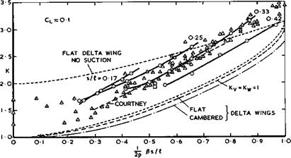
(1957) . Analytic solutions can also be found for other special cases if the condition of zero load along the leading edge is dropped and physically unrealistic infinite suction peaks admitted. When both the integrated chord – wise loading and the integrated spanwise loading are elliptic, a ‘lower bound’ of the lift dependent drag is obtained under the assumption that Bs/J. is small compared with unity, according to R T Jones (1952). This leads to the standard values Ky = Ky = 1 in (3.46) or (4.140), and the drag then increases with Bs/Л as shown in Fig. 6.65. The planforms of flat wings to give such loadings, and especially zero load along the trailing edge (1.(1) = 0) , must have streamwise tips, according to slender wing theory. A flat delta wing has a slightly higher drag, according to linear thin-wing theory. P Germain (1957) and P Germain and M Fdnain (1962) have shown how this can be reduced by the application of warp and an ‘optimum optimorum’ obtained, including the case of a delta wing with nominally sonic leading edges, i. e. Bs/Л = 1 . We see from Fig. 6.65 that the drags obtained by these theories do not differ very much from one another. In general the lift-dependent drag is proportional to and can be reduced by reducing the planform shape parameter p ; that the vortex drag is smaller the larger the value of s/i ; and that the wavedrag increases with both Mach number and s/Л, as indicated in Fig. 6.65 (see also Fig. 4.75).

What really happens can be seen from the experimental values in Fig. 6.65 based on A L Courtney (1960) and J Weber (1976). They all lie above the theoretical curves but below the curve for a flat delta wing with linear lift and no suction along the leading edges, as long as Bs/f. is reasonably small.

LIVE GRAPH

Click here to view

Lifting wings at supersonic speeds

Fig. 6.65 Overall lift-dependent drag factor for uncambered slender wings

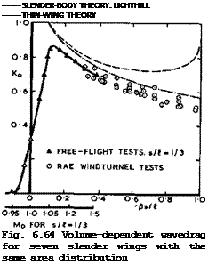
This is an indication of the existence of non-linear lift, generated by the leading-edge vortex sheets, and a corresponding drag reduction which is con­sistent with that observed at low speeds (see e. g. Fig. 6.33). This effect becomes weaker as Bs/Л approaches unity and then disappears altogether, which is consistent with the description of the effects of compressibility on the development of the vortex sheets given in section 6.3 (see e. g. Fig. 6.28). The lines through the circles in Fig. 6.65 represent the same family of thick slender wings whose volume-dependent wavedrag is shown in Fig. 6.64. We find that the lift-dependent drag factor varies with the value of s/Л and improves as s/л increases, for given Bs/Л. The triangles in Fig. 6.65 have been taken from data from various sources as collected by A L Courtney (1960). For uncambered wings with streamwise tips, Courtney suggested that

К « Ky + Ку2(Є8/Л)2 = 0.75 + 2.55 Bs/Л (6.75)

gives a good approximation for estimation purposes. This implies that neither Ky nor Кад are strictly constants. Figs. 6.64 and 6.65 together summarise much of what we know about the drag of plane slender wings at supersonic speeds.

The experimental values obtained so far provide some incentive to try to reduce the lift-dependent drag by the application of warp. The aims and methods are much the same as those already discussed in section 6.6. The simplest form of warp is conical camber, and this has been applied with some success to design wings with a relatively low drag, e. g. by J H В Smith &

К W Mangier (1957), G G Brebner (1957) and by V S Holla et at. (1972). In another paper, V S Holla et at. (1972) also evaluate the lift and drag of such wings at off-design Mach numbers. But there is also another design objective of practical importance, and that is to trim the aircraft by means of warp without incurring a significant trim drag.

The problems of balancing and of trirming are fundamental in the design of the kind of slender aircraft in which we are interested here: a tailless

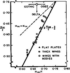
aircraft consisting of a wing of practically constant geometry or of a wing with only a relatively small fuselage (see Fig. 6.7). For the aircraft to be statically stable in longitudinal motion, the increment of lift produced by an increment of incidence must act at or just behind the centre of gravity under all flight conditions. This increment of lift acts at the aerodynamic centre, which is usually furthest forward under the approach condition of low speed and high incidence, so this is where the centre of gravity should be. We have already seen from Fig. 6.51 that the position of the aerodynamic centre at low speeds is always ahead of the centre of area, and the first problem is then to find a planform and a volume distribution which meet the main require­ments of stowage and weight distribution and put the centre of gravity in the right place. The second problem arises from the fact that the centre of pressure on flat wings moves aft as supersonic flight speeds are reached, by as much as 7 or 8% of the overall length, as we have already seen from Fig.

6.24. We want to demonstrate now by some examples how this problem can be solved aerodynamically and the centre of pressure shifted forward at super­sonic speeds by means of warp, following the work of J H В Smith (1959) and J H В Smith et at. (1965) (see also L C Squire (1965)).

A simple way of taking off the extra lift generated in the region of the trailing edge at supersonic speeds would be to defteot trailing-edge flaps upwards. This is a wasteful procedure, as has been shown in calculations by J R Richardson (1957), who compared several delta wings with flaps deflected for trim with a simple, smoothly cambered wing and found that the smooth camber offers a considerable reduction in drag for the same trimmed lift.

This means that warp should be designed to shift the load further forward. According to Munk’s stagger theorem, the vortex drag need not be affected by such a fore and aft shift. But the lift-dependent wavedrag may be changed, as it depends primarily on the lengthwise distribution of the integrated crossload. Other aspects to be considered are the possible introduction of large adverse pressure gradients, which might lead to unwanted flow separa­tions; and also the introduction of large droop angles, which, when combined with large edge angles over the front part of the wing, might hamper the development of non-linear lift (see section 6.4). In general terms, the warp will be designed for a CL-value which is considerably below that reached at low speeds (see e. g. Fig. 6.2) so that it can be expected that the centre of pressure at low speeds will be close to the aerodynamic centre.

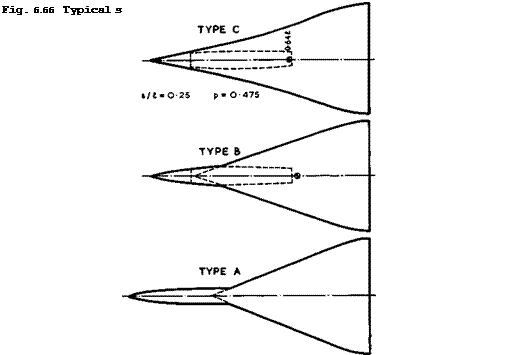
Three possible configurations of a transport aircraft with about 175 seats, for flight at a cruising Mach number Mq = 2.2 across the Atlantic, are shown in Fig. 6.66, as proposed by D Kuchemann & A Spence (1961). Some of the design parameters are given in the table below. All three types are meant to

Type A

Type В

Type C

V*

0.65

0.78

1 .00

s h

0.24

0.25

0.25

p

0.39

0.45

0.475

6s/A

0.47

0.49

0.49

6s/*w

0.72

0.62

0.49

Some design parameters of the configurations in Fig. 6.66

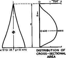
be reasonably realistic and have been designed by J Weber to provide sufficient Volume in the right places. The volume distribution of wing C is shown in Fig. 6.67, which also indicates how the passenger cabin can be accommodated in a bulge within the wing. The volume-dependent wavedrag of this symmetrical configuration is reasonably low: its measured value of Kq was 0.76. The table indicates that Type A may have an advantage over the others because of its low nominal value of p but its wing is no longer aerodynamically slender at cruise. It is not yet known how such a configuration can be trimmed aero­dynamically, and we concentrate here on Types В and C, which may be regarded as slender enough for the application of the design methods discussed above.

The starboard leading edge of wing C is given by

Подпись: 2 l Подпись: >Lifting wings at supersonic speeds

Lifting wings at supersonic speeds

(6.76)

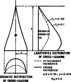
with the centre of area at хса/Л =0.69 . It was estimated at the time of design that the position of the aerodynamic centre at Cl 0.5 and Mq s» 0.2 would be at xac/A =0.64 . The centre of gravity is supposed to be at the same point to give neutral longitudinal stability in the approach. The wing is intended to cruise at Mo = 2.2 and Cl = 0.1 without control surface deflections, with the same position of the centre of gravity. For the sake of achieving a relatively low drag and of moderating the required leading – edge droop, only half the cruising Cl is produced by warp and the other half by an appropriate angle of incidence, as indicated in Fig. 6.68. It is assumed that the two lift and pitching moment contributions are additive.

F(>0t

Lifting wings at supersonic speeds


Lifting wings at supersonic speeds

TYPICAL CROSS-SECTION OF AN UNCAMBERED WING

(*=««)


Fig. 6.67 Typical shapes and area distribution of a thick slender wing

Lifting wings at supersonic speeds

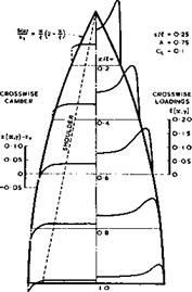
Fig. 6.68 Typical spanwise and lengthwise loadings over a warped slender wing


The lift contribution due to the angle of incidence then acts at the high­speed aerodynamic centre which is taken to lie about 8% of the length behind that at low speeds, at xac/£ = 0.72 . The lift contribution of the warp, designed for Cl = 0.05 with the attachment lines along the leading edges, must then act at a point which lies 8% ahead of the aerodynamic centre at low speeds, at xCp/f = 0.56 , so that the combined loading at Cl = 0.1 acts again at x/i. = 0.64 , the centre of gravity.

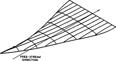
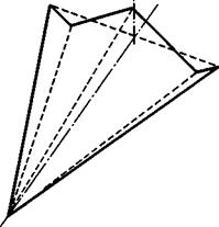
The warped mean surface of this wing was designed by the method of J H В Smith et at. (1965) described above and details about the many other aspects taken into account in the design may be found in the original paper. The resulting shape is typical for this kind of wing design; it is illustrated in Fig. 6.69,

Lifting wings at supersonic speeds

Fig. 6.69 Mean surface of warped slender wing at attachment angle of incidence

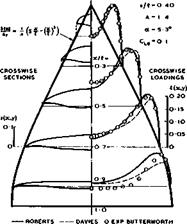
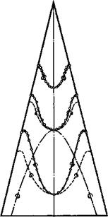
in which cross-sections and chordwise sections are combined to give a three­dimensional impression of the mean surface at its attachment angle of inci­dence. (An isometric projection has been used, where the lengths along chord and span are reduced relative to verticals in the ratio l:/3.) The arbitrary function of у which enters the calculation of the mean surface has been chosen to make the trailing edge straight. The cross-sections show the characteristic droop of the leading edges required to produce attached flow at a positive lift coefficient, with the droop concentrated close to the leading edges towards the rear and spread over the whole cross-section at the front. These cross-sections are arranged lengthwise so that the angle of incidence of the centre line is much larger at the front than at the rear, giving the required shift of the centre of pressure forward from the aerodynamic centre. The mean surface can be described as having negative camber on the centre line, changing through inflected shapes to positive camber near the tips, with marked washout from root to tip. Even with these large changes in wing slope, the local loading f(x, y) still has pronounced peaks inboard of the leading edges and a deep valley along the middle, like those in Figs. 6.57 and 6.58.

Wing C was tested by A 0 Ormerod (1962, unpublished), both as a symmetrical wing and in combination with the warped mean surface described. Some results have been quoted by A Spence and J H В Smith (1962) and by J H В Smith et at.

(1965) and show that this design method can be successful. At the design

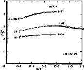
Mach number of 2.2, the attachment lift coefficient was produced at an angle of incidence within one-tenth of a degree of the calculated value. At Cjj = 0.05 , the position of the centre of pressure was at xcp/A = 0.57 , i. e. less than 1% of the length behind the intended position. The actual shift in aerodynamic centre between Mq = 2.2; Cl = 0.05 and low speed, Cl = 0.5 , was almost exactly 8% of the length, as assumed in the design. Because the aerodynamic centre of the plane wing at low speeds was about 1% of the length further forward than assumed, and the aerodynamic centre of the warped wing a further 1% ahead of that, the trimmed Cl at Mq *» 2.2 was 0.08 instead of 0.10. At the intended cruising lift coefficient Cl = 0.10 , the measured lift-dependent drag factor was К = 1.93 , which is marginally less than the value of 2.00 measured on the unwarped wing. These values are marked as square points in Fig. 6.65. They are significantly tower than those of a corresponding unwarped wing of delta planform (K = 2.25) or of a thin delta wing with no suction (K = 2.4) . Results very similar to these were obtained with another warped wing designed to have attached flow at Cl = 0 , but to be

trimmed again at Cl = 0.1 . This implies that this method for trimming slender

wings is not very sensitive to the value chosen for the attachment Cl. Differences may arise at off-design Mach numbers, and this makes it possible to consider, and to allow for, conditions at other flight Mach numbers in an actual design, for example, flight at a high subsonic speed.

We have seen from the results in Fig. 6.7 that interest in future designs of supersonic transport aircraft should concentrate on either wings alone or wings with fuselages which protrude only slightly ahead of the wing. With this in mind, the configuration В in Fig. 6.66 was designed. The short fore­body has circular cross-sections, and the sharp-edged wing emerges from the

body side about 30% of the overall length from the nose. Further aft, the body disappears into the wing thickness so that the rear part of the configura­tion can be the same as that of the wing C described above. The volume dis­tribution is such that it can include a cabin with the same number of pas­sengers as that of wing C. We must also bear in mind the discussion of the flow past fuselages and of wing-body interference in sections 5.5 and 5.7 and remember that a round body is a difficult shape on which to produce a chosen distribution of lift of significant magnitude without undesirable uncontrolled flow separations. Therefore, such lift and interference should be designed out as far as possible. A simple way to reduce the interference of the fore­body on the lifting properties of the wing is to arrange the forebody to point into the incident stream at the attachment condition. There is then no body upwash field to interfere with the wing flow and be taken into account in the calculation of the warp distribution. For the distribution of warp to be compatible with this direction of the body, the local angle of incidence of the wing must vanish at the apex. This can readily be achieved in the design method of J H В Smith et al. (1965). The body can then be carried forward from the apex of the gross wing into the wind direction and backward from it along the centre line of the gross wing. The lift carried on the body forward of the wing root is then close to that postulated for the gross wing forward of the same station and, since this lift is small, the correspondence should be close enough for the properties of the wing-body combination to be treated by the methods described for wings alone. Moreover, the upwash generated by that part of the body ahead of the root of the gross wing should also be close to that generated by the portion of the gross wing ahead of the root and should again be small.

A model designed in this way and a corresponding symmetrical model were tested by C R Taylor (1962, unpublished) and some results have been quoted by

A Spence & J H В Smith (1962) and J H В Smith et at. (1965). The attachment lift coefficient of 0.05 was again reached at about one tenth of a degree from the calculated attachment angle of incidence. At Cl = 0.05 , the measured centre of pressure was about 1% of the length of the gross wing behind its intended position. The required forward movement was slightly under-estimated so that the trimmed lift coefficient was again about 0.08. The measured lift – dependent drag factor was К = 1.95 for the warped configuration, as against 2.05 for the symmetrical one, at Cl = 0.10 and Mq = 2.2.

All these results indicate a substantial measure of success for the design procedure and calculation. We may conclude that the trim problem can be solved aerodynamiaally without incurring a trim drag, and that warp can be designed by the methods described as successfully for configurations with short forebodies as for wings alone, provided the bodies can be shaped to fit the flowfield of the wing.

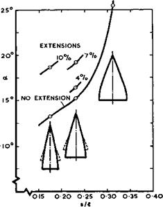
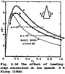
This aerodynamic solution to the trim problem should be the most attractive among the various possible solutions, which include the following: trailing edge flaps may be deflected downwards at low speeds, which can be quite effect­ive but requires complex measures for trimming out by means of a foreplane or of direct jet lift from a special engine installed in front; Kirby’s leading – edge extensions, discussed above, could be an effective means for trimming the aircraft at low speeds when the centre of gravity is put in a position suit­able for cruising flight, but these have not yet been worked out in detail and engineered; lastly, the problem can be circumvented altogether by mechanical engineering in that the centre of gravity is shifted about from one position to another in the manner of the ‘Duke of York’ by pumping fuel fore and aft, as required, during flight.

The methods described so far are intended primarily for the design of relati­vely large transport aircraft. If the slender-wing concept is to be applied to smaller combat aircraft, a fuselage is necessarily more prominent. The volume is then usually asymmetrically disposed about the mean surface of the wing and the fuselage does not fit the flowfield of the wing. The body may generate its own compressions and expansions in the flowfield, and these may be used to advantage in the design if they are superposed on the wing flow in suitable places. For example, expanding flows past bodies placed on the upper wing surface, or compression flows past bodies placed on the lower surface may be used to increase the lift and possibly the lift-to-drag ratio and also for trimming purposes (see e. g. D Kilchemann (I960)), in a similar manner to wing warp, on large and on small wings. How lift and volume effects can be com­bined in a powerful way in the design of non-slender lifting bodies will be discussed in detail in Chapter 8. Here, we refer to the work of J R Spreiter (1950) and of W C Pitts et al. (1957) on slender-wing-body combinations and to other methods which have already been mentioned.

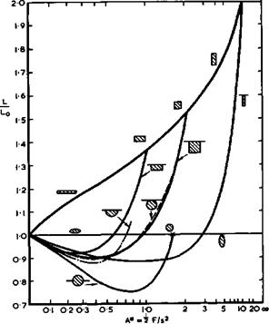
For slender wing-body combinations, the lift acting on that part of a configu­ration upstream of a given transverse plane depends only on the shape and size of the section of the configuration cut by that plane and on the streamwise rate of change of the section. The size of the body can be described by the parameter A* = jF/s^ , where F is the cross-sectional area. The effects which volume asymmetrically disposed may have on the lift are summarised in Fig. 6.70, from results obtained by R S Bartlett (1964) for circular cylinders carrying wings at different vertical positions, by H Portnoy (1968) for semi­circular bodies mounted beneath wings, and by R D Andrews (1968) for fuselages with rectangular cross-sections. In all cases, the bottom surface of the

LIVE GRAPH

Click here to view

Lifting wings at supersonic speeds

Fig. 6.70 Lift generated by wings and bodies

fuselage is assumed to be parallel to the wing and the side-surfaces are assumed to lie along the freestream direction, i. e. the fuselage does not produce either streamwise compressions or expansions by itself in the trans­verse plane considered. The calculated lift L is expressed in terms of the lift

L0 “ 2raIIpV0!t

carried by a thin slender wing of the same span at the same angle of incidence, which is the linear lift term in (6.38). We find that wingless ellipses always give L = Lq, whereas wingless rectangles produce a lift which increases monotonically with A* . On all the other configurations, with wings, the interference is unfavourable at first, as A* increases, and L/Lo reaches a minimum. L/Lq then increases again as A* increases further. The calcualted lift gains above that of the wing alone can be substantial, but the results in Fig. 6.70 may only give an indication of the general trends: it is not clear how the flows implied in the theory can be realised physically.

Lastly, we mention briefly a special problem which may arise in the design of ogee wings with pronounced changes of the local angle of sweep along the lead­ing edge, where the leading edge may be nominally subsonic along some parts and nominally supersonic in others. Such shapes may have some attraction

because they have low values of the planform shape parameter p, which could lead to low drag values according to (4.140). Possible types of flow around swept leading edges which are nominally near-sonic have been described by A Stanbrook & L C Squire (1964) and have also been investigated by E Y C Sun (1964). The singularities which linear theory predicts for wings with mixed subsonic-supersonic leading edges have been cleared up by J H В Smith et al. (1968). However, there is no evidence that such wings have real advantages over wings which are aerodynamically slender and have the simple stable type of flow associated with them.

6.9 Some problems of complete aircraft. Since slender aircraft as considered here are basically constant-geometry wings, many of the problems concerning the complete aircraft have already been discussed above in the context of wings alone. In particular, some of the work on problems of stability and control at low speeds has been mentioned in section 6.5. Here, we want to follow this up by a brief discussion of some further problems concerned with flight dynamics; propulsion and engine installation; and sonic bangs.

In the field of flight dynamics and handling characteristics, we note that the design concept of slender wings implies that some problems which are prominent in the design of classical and swept aircraft simply do not arise: problems associated with variable-geometry devices or with interference effects between the wing, the fuselage, and the tailplane assembly do not appear in the design of constant-geometry slender-wing layouts. On the other hand, we must be aware from the beginning that we are in the middle of a development which may bring about radical changes: from the classical approach of designing for the dichotomy of stability and control to the introduction of active control as an integral part of aircraft design. These matters have been set out clearly in a review by W J G Pinsker (1974) of the scope of active control in the design and operation of aircraft. When we discuss below the more conventional approach to these problems, we should bear in mind that future developments may bring about new and improved design methods for automatic control, stabil­ity and control augmentation, artificial static stability, gust and flutter alleviation, and various methods for reducing wing loads. The application of these methods may alter many design and operating traditions and affect not only the aerodynamic but also the structural design and bring with them considerable benefits. For example, Pinsker has estimated that, by placing the centre of gravity behind the aerodynamic centre of a typical slender transport aircraft, the lift available for take-off and landing at a given angle of incidence could be increased by as much as 20%, and the drag reduced.

There is an important role of theory and calculations in studies of flight dynamics and in the refinement of flying qualities, as explained by H H В M Thomas & A J Ross (1972) and W J G Pinsker (1972). But much of the information needed has to be obtained from experiments, especially from flight tests, when transient responses in manoeuvering flight are involved. The problem of identifying the relevant aerodynamic parameters from the results of flight tests has been discussed by V Klein (1973) and A J Ross (1974). This supplements the work of A F Waterfall (1970) and of С H Wolowicz (1972) already mentioned in section 5.10.

Consider now some specific problems which are typical of large slender air­craft. On the airfield, there is the problem of rotation at lift-off and its implication for tail clearance requirements. The dynamics of this motion have been clarified by W J G Pinsker (1967). Piloted simulator studies by В N Tomlinson & T Wilcock (1967) revealed no serious problems and demonstrated the usefulness of a take-off director device. Two conditions on the approach to land, which might be expected to pose some problems are: flight in strong crosswinds and associated turbulence and the sidestep manoeuvre which may be required to align an aircraft with the runway when it breaks cloud and finds itself displaced laterally from the runway. The response of slender aircraft to sidegusts and means for its suppression have been worked out theoretically by В Etkin (1959) and by W J G Pinsker (1961). The theoretical results have been confirmed and supplemented by simulator studies and by flight tests with the HP 115 and ВАС 221 research aircraft, see A McPherson (1968) and F W Dee et al. (1968). The problems have been reviewed in the context of automatic landing by M J Lighthill (1962). Pilots have not reported any particular difficulties. Landings have been made with the ВАС 221 aircraft in cross­winds up to 12 knots, with a total wind of 20 knots, using the crabbing tech­nique, where the aircraft retains a moderate angle of yaw, or drift, during landing. Considerable control activity was required throughout the range of test conditions. Because of the aircraft’s relatively high approach speed, the highest drift angle at touchdown was only 4|° and the pilots either removed the drift by gentle rudder application, or landed without correcting the drift. Sidestep manoeuvres were made from an initial displacement of over 100m from the centre line of the runway, starting at an altitude of about 100m, in crosswinds up to 10 knots. Pilots found the coordinated S-turn easy to perform, despite the oscillatory roll response to aileron inputs. The largest bank angle used was 30°, and the time required to complete a sidestep manoeuvre was comfortably between 10 and 15 seconds. We have already mentioned in section 6.5 the favourable effect of ground proximity in these manoeuvres.

Thus slender wings are inherently easy and safe at take-off and landing.

There is again the problem of the vortex wake and its effect on following air­craft, which has already been discussed in section 5.7. There is evidence that the vortex cores behind slender wings decay and disappear much sooner than those behind classical aircraft (see e. g. R L Maltby & F W Dee (1971) and G H Lee (1973)), so that the vortex wake of an aircraft like Concorde presents less of a hazard than that of a classical aircraft of similar size.

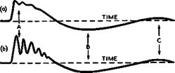
Another special problem is the behaviour of slender wings on entering and leaving vertical upgusts and in flight in continuous turbulence. Experimental measurements of the transient pressures on a slender wing in a vertical gust, obtained in a specially designed facility, have been reported by G К Hunt et al. (1961) and by D R Roberts & G К Hunt (1966). A remarkable result of these tests was that the extra lift due to an upgust takes some time to build up, whereas it vanishes much more quickly when the wing returns to undisturbed air. This behaviour has not yet been fully explained, but several theoretical models of gust penetration have been discussed by G W Foster (1974). When working out the gust response, it is necessary to take account of the flex­ibility of the aircraft. Theoretical studies of dynamic aeroelastic effects on stability, control, and gust response have been carried out by E Huntley (1961), J К Zbrozek (1963), W J G Pinsker (1963), C G В Mitchell (1967) and

(1970) , and E G Broadbent et al. (1972). Further experimental work has been described by J M Simmons & M F Platzer (1971) and by J H Horlock (1974).

Another phenomenon which is peculiar to slender aircraft is flight at or near the zero-rate-of-climb speed (Vzrc) which is defined as the minimum speed, under a given set of conditions, at which an aircraft can maintain level flight. Such a condition obviously exists for all types of aircraft, but it has no operational significance on classical and swept aircraft which stall.

On slender aircraft, however, with no stall and with a large increase of lift-dependent drag at low speeds, flight at low altitude near this condition can be potentially hazardous (although much less dangerous than a conventional stall), since the pilot may not be aware of approaching or passing the zero – rate-of-climb speed because adverse aerodynamic handling features, which normally precede the stall and warn the pilot, are absent in this case. Furthermore, as the zero-rate-of-climb condition is not purely aerodynamic in origin, it is not associated with a particular equivalent airspeed, as is the conventional stall, but the zero-rate-of-climb speed varies with altitude, power setting, aircraft weight, air temperature, and aircraft configuration. There are three main problems of practical importance: the likelihood of the airspeed falling below VZrc ; the accuracy of determining the value of Vzrc; and the consequences of a speed reduction below VZrc in terns of the height losses incurred during the recovery to a speed safely above Vzrc • These problems have been clarified and solved for practical purposes by theoretical work of W J G Pinsker (1966), by flight tests by C S Barnes & 0 P Nicholas

(1967) , and by simulator studies by T Wilcock (1970). The experimental results agreed very closely with the theoretical predictions. It turns out that the energy associated with the height loss is used partly to increase the speed of the aircraft and partly to overcome the excess of drag over thrust when flying below Vzrc • As would be expected, the first effect is generally by far the larger but, in some manoeuvres, the drag term accounted for up to 30% of the total height loss. It also appeared that the best recovery technique is the most rapid one possible, to be effected by a positive manoeuvre involving a brief but rapid loss of height during gain of speed.

In this context, we mention a related problem which is not confined to slender wings only, namely, that of the glidepath stability of aircraft flown under speed constraint. There is a tendency towards a speed instability when an aircraft is flying in the approach on the backside of the drag curve. This may be corrected by the use of an autothrottle: the system can provide an absolute speed hold, i. e. the airspeed can be maintained even in the event of substantial changes in flightpath angle. Thus the modern autothrottle allows the pilot to select the desired approach speed and thereafter to virtually forget airspeed as a parameter to be monitored further. However, this system inhibits the fundamental energy-exchange mechanism between speed and height which normally stabilises the glidepath (see e. g. J G Jones (1971)), so that the aircraft can rapidly change its flightpath by a substantial amount without the normal self-corrective action coming into play and without the speed changes which might otherwise have alerted the pilot. This phenomenon has been clarified by W J G Pinsker (1971) who suggested that, when autothrottles are to be used in otherwise manually-controlled approaches, the speed lock should be removed or at least weakened.

Yet another instability which may be encountered by slender aircraft at very high angles of incidence is a form of sideslip divergence, i. e. a tendency to diverge to higher angles of yaw, when all lateral modes of motion of the air­craft, including the Dutch roll (see section 6.5), remain stable. In flight tests at very high incidence with the ВАС 221 research aircraft, it was observed that pilots applied tight aileron control so as to maintain level bank angle. Assuming such a bank-angle constraint, W J G Pinsker (1967) then developed a theory which suggested that the condition could be alleviated by reducing the adverse yawing moment due to aileron deflection. This was realised on the aircraft by an appropriate interconnect between the ailerons and the rudder. Subsequent flight tests confirmed the efficacy of this technique.

No serious stability or handling problems are known to arise during the super­sonic phase of the flight of slender aircraft, although there is an influence of the variation of engine thrust with speed and height on the dynamic stab­ility of the longitudinal motion. This has been discussed by G Sachs (1972). There have been fears that a slender aircraft might respond excessively to an engine failure at supersonic speeds, but these have now been completely allayed by a great deal of research work and information from flight tests, which has been summarised by C S Leyman & R L Scotland (1972).

This brings us to a brief discussion of some problems of propulsion and of engine installation. Means for generating propulsive forces have already been discussed in Chapter 3 and, considering the various types of engine available, we may conclude that a straight turbojet engine is very suitable for flight at a Mach number of 2 or just above that. As discussed in section 6.2, such an engine should also provide the thrust needed for take-off. Future develop­ments may go beyond this and use engines with more complex and efficient cycles, such as a variable-cycle engine in which the airflow is temporarily increased at take-off, to reduce engine noise, without increasing the frontal area of the engine.

It now remains to decide how such an engine should be installed. Some of the design methods discussed in section 5.9 still apply but, in the case of slender wings where the means of providing volume and lift can already be integrated, it is possible, in principle, also to integrate the means of propulsion with them. In an ideal and simple case of turbo-jets of equal intake and exit area, where the intake is running full and the jet is fully expanded at the nozzle exit, the engines need not be installed in isolated nacelles. Instead, they may be installed on the upper or the lower wing sur­face in such a way that a streamtube of the wing flow is used in part as the external surface of the powerplant, with the bulk of the engine buried inside the wing. This is quite possible in principle with a thick lifting wing like wing C discussed above. If the powerplant is small enough, the external pressures and forces on the combination are the same as those on the wing alone, to a first order, and the internal forces on the installed engine are the same as on the engine in isolation. This implies that the wing can be designed without taking account of the engine, and that the engine may be installed without any additional external drag, in contrast to podded instal­lations on swept wings, say, where the installed drag of an engine may be twice, or more, the drag of the isolated engine nacelle alone. As we shall see, we are far from achieving this ideal state in practice and we depart from it in many ways, for various reasons, but the potential benefits should always remain as an aim before us (see e. g. L F Nicholson (1957)).

In principle, again, the ideal installation of engines would be near the centre line on the top surface of slender wings in the region of parallel flow between the attachment lines, as indicated in Fig. 6.19. This should avoid the poss­ible ingestion of debris which may occur with the engines installed on the lower surface; it should provide a strong backbone and lighten the structure weight; and it should provide noise shielding, as discussed in section 5.9.

We have yet to learn how to exploit these potential benefits.

A real engine nacelle, as installed on the Concorde and described by C S Leyman & D P Morriss (1971) is shown schematically in Fig. 6.71. Later minor modifi­cations, to give more performance, have been described by M Wilson (1974).

This nacelle is installed on the lower surface; it is very much larger than the actual ‘gas generator’: compressor, combustion chamber, and turbine.

RAMPS SHUT-OFF NOZZLE NOZZLE

FRONT REAR FLAPS DOORS SHROUD

Lifting wings at supersonic speeds

Fig. 6.71 Schematic layout of a supersonic powerplant. After Leyman Morriss (1971)

Intake and nozzle take up a great deal of the length of the nacelle. Another supersonic engine installation has been described by W C Swan (1974). General design principles have already been discussed in sections 3.7 and 5.9 (see also AGARD Conference Proceedings CP 91, 1971).

The supersonic compression in the intake may be partly external and partly internal, followed by a subsonic diffuser. The geometry of the intake can be varied by moving ramps. They are fully open up to about Mg = 1.3 . Above this, the ramps are progressively moved so as to reduce the throat area of the intake and to maintain the final intake shockwave on the intake lip.

E L Goldsmith (1966) has shown that the need for variable-geometry intakes arises in two ways: from the need to match engine and intake mass flows under all flight conditions, and from the need to maintain a high pressure recovery in the intake together with a low external drag over a range of Mach numbers. To avoid separation of the boundary layer from the walls, a large bleed hole is incorporated as well as doors and other openings, leading to a secondary airflow duct. Some drag is, of course, associated with such boundary-layer bleeds, see e. g. E L Goldsmith (1966). The nozzle is also of variable geo­metry and incorporates the secondary airstream. If the nacelles are grouped in pairs, a serious base-drag problem may arise. For experimental data on such layouts, we refer to tests by J W Britton (1965) and M D Dobson (1966). Nacelles installed in this way do interfere with the wing flow and are them­selves affected by it. These interference problems have been investigated e. g. by M D Dobson (1968) and J Leynaert (1974).

Next, we refer briefly to some work on tne problem of the so-called sonic bang op boom. This is the rather spectacular phenomenon which causes the pressure on the ground to change audibly, roughly in the form of an N-wave, when the system of shockwaves and expansions generated by an aircraft in supersonic flight reaches the ground. We are then interested in the farfield of the dis­turbances. The phenomenon itself has been known for a long time from the flight of projectiles, and theoretical work on the problem goes back to L Prandtl (1938). The theory of G В Whitham (1952) and (1956) and F Walkden

(1958) is concerned with farfield effects of weak supersonic disturbances and forms the basis of most of the current theories of the sonic bang. According to this theory, which is related to the supersonic area rule, the farfield effects, in a given direction, of a body or of a lifting wing are the same as those of an equivalent body of revolution. This amounts to replacing the disturbances by some equivalent cylindrical waves. There is now an extensive literature on the subject, and we refer here to reviews by С H E Warren &

D G Randall (1961) and by A R Seebass (1967), and to a practical numerical method by W D Hayes et al. (1969). Effects of density stratification, tempe­rature gradients, and turbulence in the atmosphere can now also be taken into account, see e. g. R Stuff (1970) and J A Beasley (1974), and predictions of the pressures have been made to an accuracy of about ±5%, compared with results from actual flights. Research work continues in order to take account of higher-order effects and to generalise Whitham’s approach, e. g. by M Landahl et al. (1973) and by К Oswatitsch (1972), the latter using an analytical method of characteristics. The accuracy of this method has been questioned by A R Seebass & A R George (1974), and this matter has not yet been fully resolved.

Attempts have also been made to find lower bounds to the bang or to minimise the peak overpressure or impulse, or to maximise the rise-time, see e. g.

L В Jones (1961), (1967) and (1970) and also A R Seebass & A R George (1974).

It turns out to be difficult to improve one aspect by much without adversely affecting the others, but any improvements in the general efficiency of the aircraft will tend to reduce the sonic bang also. Specifically, increases in the lift-to-drag ratio or thrust-to-weight ratio, or decreases in specific fuel consumption or overall weight, will all decrease both the overpressure and the impulse. However, the instinctive remedy of increasing the altitude of flight may actually increase the impulse due to lift. Moreover, it is at moderate altitudes that there is a chance of utilising any favourable effects that occur in the midfield, before the bang signature attains its final N-wave form.

Our knowledge of the effects that sonic bangs may have on people and on build­ings is still rather incomplete and uncertain. It seems to emerge that the effects on people are psychological rather than physical, and thus very difficult to assess. Many tests have been made on the effects of bangs on various structures, such as window glass in a building (see e. g. G W Zumwalt

(1966) ) or bridges (see e. g. V X Kunukkasseril & R Ramakrishnan (1974)). Historic buildings, particularly churches, were at one time thought to be in special danger of damage by bangs, but it seems clear now that the bang noise is generally less than that caused by such natural hazards as bells and organs. Many of these tests have been made by bang simulators (see e. g. J J Gottlieb

(1974) ), and we mention here the portable simulator for field use developed by N D Ellis et al. (1974). These devices have been applied, for example, to test the lifetime of plaster panels; a study which led to the conclusion that plaster in good repair is unlikely to be significantly damaged by repeated exposure to sonic booms generated by overflights of supersonic transport air­craft (see В R Leigh (1974)). In another study by 0 V Nowakiwsky (1974), the effects of simulated booms on the behaviour of car drivers were examined statistically, leading to the conclusion that current commercial supersonic aircraft under normal flight conditions will not produce adverse effects on a driver’s stopping distance or his ability to follow a particular course. We may mention in this context that supersonic transport aircraft are not expected to have any other harmful effects on the environment; they will cause climatic effects far less than those minimally detectable.

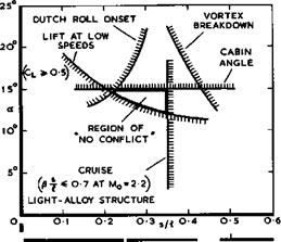
Finally, it may be useful to summarise in one simple illustration some of the limitations which arise in the design of slender aircraft from various stabi­lity and performance aspects and to demonstrate that there is a region where these are not in conflict. Several of the aspects which have been discussed impose limits on the geometry of slender shapes suitable for supersonic trans­port aircraft. How all these fit together is shown in Fig. 6.72, which

LIVE GRAPH

Click here to view

Lifting wings at supersonic speeds

I J..

О I 2

A FOR DELTA WINGS

Fig. 6.72 Various typical design limitations


summarises in a general way the essential limitations for typical conditions. The geometry of the aeroplane is simply represented by the shape of the box, s/£ , into which it fits. A number of the limitations are concerned with the low-speed behaviour. A line on the left-hand side gives an indication of the region which would be dominated by the onset of the Dutch-roll motion. This could now be defined in more detail as a result of the theoretical work men­tioned above, but we find that it does not present a serious practical limita­tion. On the right-hand side, a line is drawn beyond which vortex breakdown and significant pressure fluctuations on the wing surface may be expected.

The line is drawn for an angle of sideslip of 5°, which corresponds roughly to a crosswind of 15 knots in the approach. A third line, drawn at a = 15° , is meant to indicate that the cabin floor angle cannot be allowed to exceed certain values during take-off and approach, mainly for reasons of comfort.

The precise limiting number depends on the particular layout; and other criteria such as undercarriage length may be more practical, but some limit of this type always occurs. A fourth consideration is the lift coefficient which must be available in the approach to ensure safe landing speeds. At best, Cl – 0.5 for a long-range aircraft is a suitable criterion. These four low-speed limitations leave a region within which the proportions of an aircraft could be chosen. But on the right-hand side, the region will be bounded by considerations of cruise performance and here, for simplicity, a very complex aspect has been reduced to one line, defined by the assumption that the box into which the aircraft fits is aerodynamically slender at Mach numbers for which light-alloy structures are usable. All these limitations taken together leave a region within which the various requirements can be met and are not in conflict: no special measures are needed in order to meet the various conditions. This compatibility of the design aspects confirms that slender wings do indeed constitute a useful major type of aircraft.

All the matters dealt with in this chapter refer to A New Shape in the Sky (see M В Morgan (1972), R D Fitzsimmons (1974), R Chevalier (1974)). Concorde and its Russian counterpart the TU 144, represent the first generation of this new type of slender aircraft. They will have to prove their worth.

Non-lifting wings at supersonic speeds

6.7 We have already discussed wings in supersonic flows very briefly in section 3.4, and we have used a general relation (3.44), or (4.140), for the wavedrag due to volume, to demonstrate the importance of this contribution to the drag force which occurs when Mq * 1 (see e. g. Fig. 4.75). Now, we want to consider the volume-dependent effects in more detail for sharp-edged slender wings with leading edges which lie well within the Mach cone from the apex, so that Bs/Л <1 , as in Fig.

Подпись: 6.60, where the Mach angle a = cot' selves first to inviscid flows.

In the theoretical approaches which are suitable for design purposes, the assumption is usually made that the wing causes only small perturbations.

Non-lifting wings at supersonic speeds Подпись: (6.50)

This also provides the justification for treating thickness effects separately from lift effects. The general potential equation (2.2) or (6.31) is then again linearised:

Non-lifting wings at supersonic speeds Non-lifting wings at supersonic speeds Подпись: (6.51)
Non-lifting wings at supersonic speeds

As before, we may also neglect second-order and higher-order terms in the boundary conditions and fulfil these in the plane z = 0 . Again, in this thin wing theory,

where z = z(x, y) is the equation of the wing surface. If the wing is repre­sented by a distribution of sources, the simplified boundary condition (6.51) is equivalent to the assumption that the source strength is proportional to the normal component of the mainstream velocity at the wing surface. Again,

as before, the wing may also be assumed to be slender if, geometrically, its dimensions in the flight direction are large compared with its dimensions normal to the flight direction; and if, aerodynamically, the leading edges lie well within the Mach cone from the apex. Then (6.50) reduces to

(6.52)

We speak of slender thin-wing theory if the simplified boundary conditions (6.51) are used, and of slender-body theory if the boundary conditions are fulfilled on the surface. Thus we have again three possible theoretical approaches which correspond to the cases tabulated in the previous section.

There is a considerable body of theoretical work, and we refer to papers by G N Ward (1949), F Keune (1952), M A Heaslet & H Lomax (1953), H Lomax (1955),

К Oswatitsch & F Keune (1955), M A Heaslet & J R Spreiter (1956), M J Lighthill

(1956) , J R Spreiter & A Y Alksne (1958), E Y C Sun (1964), and D Hummel

(1968) , where derivations of the basic relations may be found. A full account of the general theory has been given by W R Sears (1955). For the present purpose, we follow the work of J Weber (1957), (1959), W T Lord & G G Brebner (1959), and J H В Smith et al. (1965), which is specifically concerned with the kind of shapes we have in mind for practical applications.

Non-lifting wings at supersonic speeds

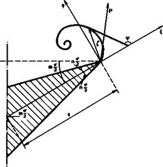
Consider first the problem of calculating the pressure distribution over the surface of a wing of given shape, according to linear thin-^wing theory. A unique solution of (6.50), which satisfies the boundary conditions (6.51), is given by

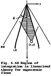
i. e. over the Mach forecone of the pivotal point, as indicated by the shaded area in Fig. 6.60. The flow at that point is not influenced by the part of the wing which lies behind the forecone. Apart from the region of integration, (6.53) differs from the corresponding relation (6.45) for subsonic flow by a factor 2: in supersonic flow, it takes a source strength four times the local surface slope to produce a certain thickness. The pressure coefficient can then be determined from the linearised Bernoulli equation (6.46), as before.

An accurate method for obtaining numerical answers has been developed by J H В Smith et al. (1965). Using an extension of finite-difference operator techniques, A Roberts & К Rundle (1973) have derived another method which can also be applied to the inverse problem of determining the shape of the wing to have a prescribed pressure distribution. M С P Firmin (1963) and (1966) provided yet another specific method as well as experimental results in the transonic speed range, which demonstrated that the transition from subsonic to supersonic flow proceeded smoothly as the Mach number was increased.

D G Randall (1958) and (1959) has introduced specific improvements to render the solutions uniformly valid when dealing with the trailing-edge region in

Подпись: Fig. 6.60 Region of integration in linearised theory for supersonic flows

subsonic flow and with the leading-edge region in supersonic flow when the leading edge lies close to the Mach cone from the apex.

Consider next the problem of calculating the pressure distribution according to stender-body theory. Equation (6.52) in the two variables у and z together with the boundary condition of zero normal velocity at the wing sur­face, determines the potential function ф(х, у,г) except for an additive function of x, which must be obtained in some other way:

ф(х, у,г) = ф|(y, z;x) + Ф2(х) . (6.55)

If the linearised boundary conditions (6.51) are used, the solution for ф| is

+s(x)

Ф,(у, г=0;х) = ^ f In |y – y’|dy’ . (6.56)

0 – s{x)

Non-lifting wings at supersonic speeds

G N Ward (1949) has determined the function ф2(х) by returning to the com­plete linearised potential equation (6.50) and satisfying the boundary conditions ф(x, y,z) = 0 and Эф(х, у,г)/Эг = 0 at the Mach cone through the apex. Alternatively, F Keune (1952) has determined ф2(х) by expanding the integral in (6.53) in a power series with respect to the semispan and neglect­ing higher-order terms. Both arrive at the same result:

can again be calculated from (6.46) for thin wings. Note that the function ф] is independent of Mq, so that ф only varies with Mach number through

Ф2 •

In many practical cases, these approximate theories may give adequate results, but they cannot be relied upon in general* Typical diacve, pan3jie8 which may arise are shown in Figs. 6.61 and 6.62 for two wings of large thickness, one

Подпись: LIVE GRAPH Click here to view —^ SLENDER-BODY THEORY

—– THIN-WING THEORY

Non-lifting wings at supersonic speeds

AO EXPERIMENT BRITTON

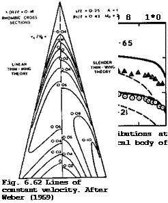
of conical shape and the other non-conical with a sharp trailing edge. Experi­mental results in Fig. 6.61 by J W Britton (1962) agree quite well with those from slender-body theory when 8s/& is small, but at &s/l = 0.65 this geo­metrically thick body can obviously no longer be regarded as aerodynamically slender. Further, the thinness assumption does not appear to be justified in this case. In Fig. 6.62, results from thin-wing theories are compared to show the difference which the additional slenderness assumption can make.

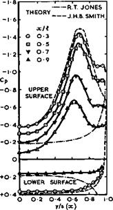
Both theories predict quite small velocity increments and the same general type of velocity distribution, with an expansion over the forward part of each spanwise station and a compression over the rear part, but there are discrep­ancies in the details, especially near the wing tips. J Weber (1957) has dis­cussed the various shortcomings of the theories. A wholly satisfactory theory for calculating pressure distributions, which can also take account of the effects of viscosity, does not yet exist.

Подпись: dy . (6.58)
Non-lifting wings at supersonic speeds

These theories have proved useful in predicting the wavedrag due to volume and especially in providing pointers to how to design wings which have a low wavedrag. Within linear thin-wing theory, the overall drag is given by

This calculation of the drag from the shape altogether involves four integra­tions. Alternatively, the drag may be calculated from the rate of change of momentum in the x-direction through a large cylinder around the body (see sections 3.1 and 3.2). This leads to the supersonic area rule, derived by H Lomax (1955), which gives the same results as those from linear thin-wing theory. It involves the determination of cross-sectional areas in oblique cuts through the body followed by the evaluation of a triple integral.

Following initial work by Th von Karman (1936), F I Frankl & E A Karpovich (1948) and G N Ward (1949) have provided a method for calculating the wave – drag of slender bodies with pointed noses, and M J Lighthill (1955) has applied this to wings with unswept trailing edges for 8s/S, < 1 , with the following result:

Подпись: DWПодпись: 0 0Non-lifting wings at supersonic speeds

Подпись: 0

C,

Подпись: 9Non-lifting wings at supersonic speeds(6.59)

where the constant к is given by

+s +s

Подпись: with Подпись: к Подпись: / Non-lifting wings at supersonic speeds Подпись: (6.60)

I I In [~~-‘SyT| e (y)s(y’ )dydy’

Non-lifting wings at supersonic speeds(6.61)

and the length і = 1 . The function F(x) and its derivatives have the same meaning as in (6.57). E Eminton (1955) and (1961) and J Weber (1959) have provided practical methods for evaluating the integrals. This relation indicates the important part which the geometry песет the trailing edge has in determining the wavedrag. For pointed bodies of revolution and for wings with cusped trailing edges, F'(l) = 0 , and the drag then does not depend on the Mach number. This is the sonio area rule for smooth bodies. But for wings with non-zero trailing-edge angles, F'(l) =£0 , and the third term in (6.59) then gives a variation of the drag with Mach number, depending on the stream – wise slope of the wing shape at the trailing edge.

Подпись: 4V0 Подпись: 128 vol 7Г .4 Подпись: (6.62)

Before considering how this fact may be exploited in wing design, we can indicate at last how we arrive at the relation (3.44) or (4.140), which has already been used so often. W Haack (1941) and W R Sears (1947) have derived shapes of bodies of revolution of given length and volume which have the smallest possible wavedrag. One of these is the so-called Sears-Haack body, which is pointed at both ends. Its drag is

This is twice the drag of the von Karman ogive forebody of one half the volume and one half the length. In (4.140), the drag from (6.62) has been used as a standard to measure the drag of any other body or wing, and Kq = 1 indicates that the body or wing has the same drag as the Sears-Haack body of revolution of the same volume and length. We see from (6.59) that the value of the volume-dependent wavedrag factor Kq of wings can vary with Mach number.

Подпись: z(x,y) Подпись: (6.63)
Non-lifting wings at supersonic speeds

We are interested here in sharp-edged delta wings with smooth surfaces. For some of these with simple, but nevertheless interesting, geometry, pressure distributions and wavedrags can be worked out analytically in elosed form (see J Weber (1957)). Such a wing is that proposed by К W Newby (1955), who also calculated pressure distributions in incompressible flow. This wing has biconvex sections in the x-direction; spanwise sections are of rhombic shape so that the thickness-to-chord ratio decreases linearly across the span to zero at the tip. The ordinates of the wing surface are given by

and the cross-sectional area distribution by

F(x) = 12 vol x (1 – x)

Подпись: (6.64)Theoretical velocity distributions over the surface of such a wing have already been shown in Fig. 6.62. The value of the wavedrag factor according to slender-body theory is

Подпись: (6.65)Ko – li (f – І ln 2 – ln 6s/*) •

For example, Kq = 0.85 for this wing when 6s/A = 0.4, i. e. it is below unity.

Another wing of simple shape has been defined by W T Lord & G G Brebner (1959)

Подпись:(6.66)

with the so-called "Lord V" area distribution:

Подпись: (6.67)F(x) = vol 7×2(l – x)(4 – 6x + 4×2 – x8) .

In this case, the value of Kg according to slender-body theory can be approximated by

tr _ ii7 1 + ^.56s/& £o

K0 ” K17 1+ 4es/T • (6*68)

Kq = 0.72 for the same value of 6s/I as for the Newby wing.

These rather low values of Kg call for a more systematic investigation of the effects of the geometry on the wavedrag. We follow here J Weber (1959), who considered a family of wings with the area distribution

F(x) = vol x2(l – x)f(x) , (6.69)

where f(x) is a polynomial, so that, in fact,

N

F(x) = vol x2(l – x) апхП • (6.70)

n=0

To obtain numerical answers, wings with rhombic cross-sections and, therefore, a linear spanwise distribution of the streamwise slope at the trailing edge were chosen:

є(у) = є(0)(1 – J y/s I) , (6.71)

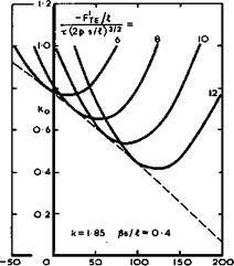
for which к = 1.85 . The drag factor according to slender-body theory can then be written down explicitly and its minimum determined by differentiation with respect to chosen parameters, for given values of s/A and 6s/A. An example is shown in Fig. 6.63 for such a family of wings. The curves for minimum drag are seen to have an envelope which represents the lowest attain­able wavedrag within the family considered. The theory predicts values of Kq which are well below unity. (The value of Kq for Newby’s wing lies

LIVE GRAPH

Click here to view

Non-lifting wings at supersonic speeds

x(2p s/03/a

Fig. 6.63 The smallest volume-dependent wavedrags of a family of slender wings. After J Weber (1959)

above the envelope and that for the Lord V area distribution lies close to it.) Kq i-s small when F* and F" at the trailing edge are large.

Although Fig. 6.63 applies only for a particular family, similar general trends have been found also with other families. Much the same curves have been obtained for area distributions which are polynomials of sixth degree (as in Fig. 6.63) and others which are polynomials of eighth degree. The results also indicate that the same values of Кл can be obtained with

* I If v

different values of F*je and Fte » and of x, p, and s/i as long as the volume x(p s/Л)3/2 and the length і are the same. This gives some free­dom of choice to the designer to satisfy other conditions. This work also demonstrates very clearly how much more insight into what really matters may be obtained from approximate solutions in closed form rather than from purely numerical solutions obtained by a computer, where the main trends may be difficult to detect and well hidden and may easily be missed altogether.

In all the cases considered so far, the trailing edge is assumed to be sharp and unswept. Equation (6.59) still applies to wings with unswept trailing edges when the trailing edge is blunt (but it excludes the base drag itself), or when a fuselage is combined with the wing (provided that any part of the fuselage behind the trailing edge is cylindrical). In the latter case the expression for the factor к is different. J Weber (I960) has derived numerical values of к for wings with blunt trailing edges and for wings with sharp trailing edges attached to circular-cylindrical bodies in midwing position. Another geometrical feature to be considered is a relatively small angle of sweepbaok of the trailing edge, which, as we have seen, might be beneficial with regard to the lift-dependent drag and for trimming purposes. The effect of swept trailing edges cannot be obtained reliably from slender – body theory. It has been investigated by J C Cooke & J A Beasley (1960) and by J A Beasley (1965), using linear thin-wing theory. These calculations are

much mere laborious and require the evaluation of a four-fold integral. The general result in all the cases considered is that sweeping the trailing edge of a given wing increases the zero-lift wavedrag, if the length and volume are held constant. The increase may be as much as 20% for a sweepback angle of about 35°. F Keune et al. (1975) have investigated slender wings with various thickness distributions, with a view to reducing the wavedrag. Variational methods have been applied by A Nastase (1974), (1975) to determine the opti­mum optimorum’ of the wavedrag due to volume. It appears that her examples give values of Ко near 0.35 at $s/£ – 0.75 . In the same series of papers she also studied the corresponding problem for the lift-dependent drag.

The main question of practical importance is how far the predicted low values of Kq are physically realistic. Obviously, the very low values cannot be realised in practice. Short of an appeal to experiment, several checks can be made in the design of a wing. First, the result can be inspected to see whether the assumptions made in the theory have been violated. Various errors which may arise in the theories have been discussed by J Weber (1957) and (1959). Second, the pressure distribution can, and should, be calculated to see whether the flow implied looks at least physically plausible and, in particular, whether the real flow is likely to involve shockwaves which are unwanted and have not been represented. Third, the development of the bound­ary layer can be estimated to see whether separation is likely to occur in the real flow. However, an experiment will be needed in the end to resolve the many uncertainties which remain in the theoretical estimates.

Experimental results have been provided by T E В Bateman & A В Haines (1961), and other workers already mentioned above. We reproduce here the results of tests on seven different delta wings in Fig. 6.64, which all have the same cross-sectional area distribution (that of wing 5 of W T Lord & G G Brebner (1959)) but different values of s/l and of the overall volume, following an analysis by J Weber (1976). In spite of some scatter, these results clearly

Подпись:
LIVE GRAPH

Click here to view
confirm that the general theoretical trends are realistic. The theory can indeed be used to design wings with Kq-values well below unity. Thus the estimates made in section 6.2 are not over-optimistic and should be attainable. The tests also indicate that Kg is a useful parameter for correlating results obtained for different wings. Fig. 6.64 includes results from tests on free-flight models by C Kell (1958) so that we can see what really happens at and near sonic speed. Both slender-body and thin-wing theories break down there, predicting an infinite drag at Mg = 1 , whereas the actual drag approaches the theoretical values from below when 8s/& exceeds about 0.2.

In this case the actual Kg-values never reach unity; they begin to climb steadily above the critical Mach number of about 0.95 and reach a maximum value near about 6s/I =0.1 , as would be expected physically. The results also indicate that the sonic area rule is quite inadequate for slender wings: the drag of the equivalent body of revolution (the first term in (6.59)) gives a value of Kg of about unity in this case, with a corresponding value of

2.1 for Kg in the case of the Newby area distribution given by (6.64).

Neither of these values has any physical meaning.

The design of warped wings with attached flow

6.6 To maintain the same type of flow throughout the flight range and, specifically, to obtain a flow with separation all along the leading edges and coiled vortex sheets on one side of the wing only, the wings must have such a shape that attachment lines lie all along the leading edges at one particular condition. All wings with flat chordal planes fulfil this condition automatically, at Cl = 0 . If this condition is to be fulfilled at Cl Ф 0 , the wing must be cambered and twisted or warped, in such a way that the load falls to zero along the edges at this design point. For CL > 0 , the leading edges are then bent down into the local flow direction, and the appropriate behaviour of the load is to vanish like the square root of the distance from the edge. The practical purpose of designing warped wings for attachment at Cl > 0 may be to reduce the lift – dependent drag or to trim the aircraft. Here, we discuss how such wings can be designed for low speeds, leaving the design of warped wings for supersonic speeds to section 6.8.

We note that the existence of such attachment design points constitutes only a necessary condition to obtain the desired type of flow – they are not likely

to be actual operating points of an aircraft. An aircraft is likely to fly, at any speed, at a lift coefficient above the attachment Cl, when the flow is separated from the edges. A complete design method should, therefore, be able to deal with both attached and separated flows but, as we have seen in section 6.4, existing design methods for separated flows are poor. Thus a complete design method is not yet established, and this makes it somewhat uncertain what precisely the design aims for the attached-flow condition should be. On the other hand, several theoretical approaches are available to design wings for attached flow, which lead to satisfactory results because, in general, we have a flow with genuinely small disturbances. The approximate equations of motions to be used are, of course, the same as those which have been used in the design of swept wings (see Chapter 5), but the solutions are not now in a form which allows special physical effects, such as kink effects on swept wings, to be identified. This makes it more difficult to formulate physically reasonable and effective design aims.

These matters have some repercussions especially on the design of wings to have low vortex drag. We have already noted that we are not able to calculate the wing shapes which give the smallest vortex drag for a given lift and span, when the downwash along the non-planar vortex sheet, shed from a slender wing with leading-edge separations, should be constant. If, on the other hand, the trailing vortex sheet could be assumed to be essentially planar, then the lower bound of the vortex drag factor in frictionless flow is known to be Kv = 1 , according to R T Jones (1951). But this requires the spanwise dis­tribution of the chord loading to be elliptic, with an infinite slope at the tips, which is, in general, incompatible with our condition that, even in attached flow, the load should be zero along the leading edges, when the span – wise distribution of chord load has zero slope at the tips (as in Fig. 6.37). Thus we do not know how low the vortex drag can be, and we can set ourselves only the rather vague design aim to find wings with ‘a low drag’.

We are dealing here with threedimensional subsonic potential flows which are governed by (2.2). For the present purpose, this may be simplified and the boundary conditions may be applied in various ways, so that there are four main approaches and approximations, which are summarised in the table below and labelled (1) to (4). We are already familiar with these approximations:

Differential equation:

ф + ф =0 yy zz

(l – М^ф + ф + ф =0 0/Yxx yy Tzz

Boundary condition:

(2)

in a mean plane

slender thin-wing theory

subsonic linear theory

(3)

(4)

on the wing surface

slender-body theory

surface panel methods

if the perturbations can be assumed to be small, (2.2) can be simplified into

(2.28) with 6^ = 1 “ м2 , the differential equation for cases (2) and (4) in

the table above. If, in addition, the wing can be assumed to be slender, or if the Mach number can be assumed to be near unity, then (2.28) can be simplified into (3.17), the differential equation for cases (1) and (3) in the table above. A further distinction can be made as to where the boundary conditions are to be applied: either in a mean chordal plane, cases (1) and (2); or on the wing surface, cases (3) and (4). Calculation methods have been developed for all four cases.

The earliest method for slender wings, case (1)» is that by R T Jones (1946) (see also J R Spreiter (1948) and G N Ward (1949) for a discussion of the assumptions and errors involved in this method). The downwash vz(x, y)/VQ induced by a specified load £(x, y) over the wing surface is then given by

(4.66) . R T Jones’s solution for a flat thin wing has already been quoted in

(4.67) to (4.69). There are also several theories which may be regarded as being halfway between the cases listed in the table. We refer to those for not-so-thin wings by J C Cooke (1962) and for not-so-8tender-wingв by

Mac C Adams & W R Sears (1953) and by L C Squire (1960). J H В Smith (1958),

J C Cooke (1960), D Hummel (1968), and H Portnoy (1968) have applied slender – body theory, case (3); and a surface-panel method, case (4), which is adapted for slender wings, has been developed by A Roberts & К Rundle (1972). However, most of these methods do not deal directly with the design problem which we want to discuss here. Also, we have already seen (see Fig. 6.11) that some of the theories are based on a physically unrealistic model of the flow, which allows infinite velocities around the edges.

There are several practical methods for the design of warped wings according to slender thin-wing theory, case (1), notably those by G G Brebner (1957) and (1958) and by J H В Smith & К W Mangier (1957), all these for delta wings with conical camber; and by J Weber (1957) and (1960) for more general slender shapes. In all cases, the load £(x, y) and the downwash vz(x, y) are related by (4.66), and the downwash is related by the boundary condition to the slope of the chordal mean surface, from which the shape of this surface can be obtained by integration. The assumptions of this theory allow thick­ness effects to be treated separately from lift effects, so that a chosen thickness distribution can be added to the ordinates z(x, y) of the mean surface. In principle, the load can be prescribed and the shape determined, but it is not obvious what load distribution should be chosen. If the load is expressed as a sum of basic solutions, to allow some choice, then the result­ing wing shape, as well as the pressure distribution, may exhibit undesirable waviness. This is avoided in a method by R К Вега (1974) for warping delta wings to give minimum vortex drag.

J Weber (1957) and (1960) avoids waviness by applying a mixed procedure: partly, the wing shape is prescribed and, partly, some property of the toad distribution. For example, the inner part of the wing may be chosen to be flat inboard of shoulder tines, while the load falls to zero at the edges over the drooped outer parts of the wing. This is illustrated in Fig. 6.57. Aditionally, it may be specified that a hinge-tine suitable for trailing-edge controls should be straight in an otherwise warped wing. Alternatively, dihedral and anhedral may be incorporated, as discussed in relation to Fig. 6.55. Weber’s method is general enough to deal with wings with pointed nose and unswept trailing edge but otherwise arbitrary planform, with curved stream – wise and spanwise sections. A variety of aerodynamic conditions can be satis­fied, though not necessarily all at once: the pressure distribution may be chosen; in particular, adverse pressure gradients may be limited; the position of the centre of load may be specified; the drag due to lift may be reduced below that of the corresponding plane wing. One can also choose from a variety of shapes to find one that meets non-aerodynamic requirements, such as a restriction on undercarriage length. However, it is never quite clear what the choice should be and how the wing will behave in off-design conditions.

P В Earnshaw (1963) has tested an extensive series of warped wings, designed by Weber’s method and covering a wide range of parameters. The main result of these tests was an indication that the attachment condition could indeed be

The design of warped wings with attached flow

Fig. 6.57 A warped gothic wing. After J Weber (1957)

fulfilled near the design lift coefficient, and that the flow development was regular in off-design conditions. The results also indicated the shortcoming to be expected from any slender-wing theory: trailing-edge effects, which are not taken into account in such a theory, dominate the difference between the load distributions achieved in the tests and those predicted by slender-wing theory. The agreement with design values of lift and pitching moment was good only when an appreciable part of the design load was carried over the forward part of the wing.

This particular shortcoming can be overcome by the application of subsonic linear theory, case (2), or surface-panel methods, case (4). Both involve much more numerical work, but this can be carried out by a computer. In linear theory, the design probelm to determine the shape of the mean surface to sustain a given loading £(x, y) involves the evaluation of the general downwash integral (4.49). This has been expressed in a form suitable for direct numerical evaluation by M P Carr (1968), following a procedure origin­ally devised by J H В Smith et al. (1965) to solve the corresponding problem for supersonic flows (see section 6.8). An account of the method has been given by P J Davies (1971). This method corresponds to that of С C L Sells

(1969) for swept wings (see section 4.3), except that Sells’s method is more general in that it allows the downwash to be evaluated at any point on or off the mean surface.

In practical applications, one would like, in principle, to be able to specify the pressure distribution over the surface of a thick warped wing, as in the design of swept wings. Such designs have not yet been carried out. Instead, a given volume distribution Zy(x, y) is usually added to the mean surface and the pressure distribution due to volume determined separately. and added to the pressures due to lift, within the assumptions of linearised theory. The wing thickness Zy(x, y) is usually added to the mean surface in a constant direction normal to the plane of the planform, but P J Davies (1971) has shown
that, to preserve the attachment condition of the warp surface, it is more appropriate to add zv(x, y) at each point in the direction normal to the mean surface.

For completeness, we write down here how the pressure distribution due to thickness may be determined according to the linearised theory of subsonic flow past thin wings, case (2). As explained before (see section 4.3), the volume distribution is represented by a distribution of sources over the plan – form, where the source strength is twice the streamwise slope of the ordinate of the upper surface of a symmetrical wing. The disturbance velocity potential of this flow is

Подпись: SПодпись: Cx'.y')The design of warped wings with attached flowПодпись:___________ dx’dy’__________

[(x – x’)2 + e2(y – y’)2 + e2z2]* ’

…. (6.45)

With the linearised approximation for the pressure coefficient

Подпись:г _ _ _!i±

P " VQ Эх ‘

Подпись: C (x,y) The design of warped wings with attached flow Подпись: 62z2]i Подпись: (6.47)

the pressure coefficient at a point (x, y) on the wing is

This can be integrated by parts with respect to x’ , and P J Davies (1971), following M P Carr (1968), has shown how the differentiation with respect to x can then lead to an expression for Cp which is easy to evaluate numeric­ally for sharp-edged wings, on which the slope is finite everywhere:

Подпись: X(xL,y')4ST

Подпись: Cp(x,y)Jg 1 [(X – X)2 + e2(y – y’)2]*

The design of warped wings with attached flow The design of warped wings with attached flow

L ST L

and x^(y) and x^(y) are the values of x at the leading and trailing edges. The integration has been programmed by M P Carr (1968). We note that this procedure is more straightforward than the corresponding treatment of
swept wings with round leading edges and with strong centre and tip effects. Although this theory predicts an unrealistic logarithmic singularity along the leading and trailing edges, the regions affected by the singularity are small.

Davies’s method has been used to design several thick wings with various given loadings for testing in a low-speed windtunnel (see P J Butterworth (1970)). These wings are thought to be suitable for a subsonic allwing aerobus like that to be discussed in Chapter 7. For this application, s/l can be larger than for wings to fly at supersonic speeds. Also, the wing is thick enough (t/c = 0.09 at the centre line) to house the passenger cabin of an aircraft of medium size. An example is reproduced in Fig. 6.58 from an assessment of

The design of warped wings with attached flow

Fig. 6.58 A warped mild-gothic wing. After P J Davies (1974)

the accuracy of the design method by P J Davies (1973). This wing was designed to have a lift coefficient of = 0.1 and a centre of pressure

at the position хСр/Л = 0.533 at the attachment angle of incidence of ad = 5.3°. The results in Fig. 6.58 include not only the design calculations but also some obtained by the panel method of A Roberts & К Rundle (1972).

The latter is a direct calculation, producing the properties of a given shape, rather than a design calculation. It should be more accurate than linearised thin-wing theory because it takes proper account of the interference between the finite thickness and the warp of the wing, except near the leading edges where the required behaviour is not correctly represented. The comparison in Fig. 6.58 shows some differences between the loading distributions calculated from the two theories. Also, the overall lift from Roberts’s non-linear theory is nearly 10% higher than that from linear theory, and the centre of pressure is about 2% of the overall length further back at xCp/£ = 0.556 , in this particular case. No consistent improvement of the results from linearised theory could be obtained by adding second-order terms obtained from Bernoulli’s equation to the right-hand side of (6.46). Such an improve­ment requires the inclusion of second-order terms introduced through the boundary conditions, as in the general method by J Weber (1972).

Comparison with the experimental results by P J Butterworth (1970) in Fig.

6.58 for the design angle of incidence indicates that Roberts’s theory gives,
on the whole, a slightly better representation. But both theories are seen to be inadequate near the trailing edge where the actual load is significantly lower, presumably because of the displacement effect of the boundary layer. Consequently, the measured overall lift is also lower and happens to be close to that predicted by linear theory. The loss of lift at the rear also causes the experimental position of the centre of pressure to be ahead of both theoretical predictions. Thus the effects of viscosity should be taken into account in a complete design method. This could be done, in principle, in a way similar to that explained for swept wings in section 4.5, but such calcula­tions have not yet been carried out.

The experiment confirmed that attached flow was obtained at the design angle of incidence also in this example, and that separated flow developed in a regular manner at all other angles of incidence. Further, the lift-dependent drag was substantially reduced by the application of warp, as can be seen from the experimental results in Fig. 6.59. It is interesting to note that the

Подпись: Fig. 6.59 Lift-dependent drag factors of a flat and a warped mild-gothic wing. After P J Butterworth (1970) LIVE GRAPH

Click here to view drag reduction is spread over the whole C^-range tested and that it is greatest at CL-values well above the design value “ 0.1 for attached flow: the leading-edge vortex sheets induce suction forces over forward-facing surfaces. This emphasises again the need for a complete design method for warped slender wings, which can take flow separation into account. Only then can an attempt be made to obtain much more substantial drag reductions than those achieved so far. It may be significant in this context to point out that all the loadings we have seen in Figs. 6.11, 6.26, 6.27, 6.43, 6.57 and 6.58, whether for attached or for separated flow, have in common that the middle part of the wing is only lightly loaded and that the main loading is always concentrated near the leading edges. As explained in section 6.4, this can have undesir­able repercussions on the vortex drag. Sweptback wings also tend to have a lift deficiency in the middle but we know how to eliminate this by suitable design, at least for subcritical flow; with slender wings, we have not yet succeeded.

An interesting application of the slender-wing concept is the fleanhle wing or paraglider. In its simplest form, this may be a wing of delta planform, consisting of a sail-like flexible surface stretched between rigid beams along the leading edges. Other shapes may have two lobes between the leading edges and a third rigid beam along the middle. Any load is usually suspended below

the wing. Paragliders were first proposed by F M Rogallo & I 6 Lowry (1960) to transport space vehicles back to the ground after re-entry into the atmos­phere. More recently, they have been used as actual gliders. These highly cambered wings provide an instructive example of the application of slender – body theory (see e. g. J N Nielsen (1965)), together with the aerodynamic theory of sails (see e. g. В Thwaites (1961)). A great deal of theoretical and experimental work has been done, and this has been summarised and extended by К Gersten & W H Hucho (1965). Gersten calculated the shape and the pressure distribution of one-lobed wings in attached potential flow, making the assump­tions that the wings are slender and that the flow is conical. The material of the wing is assumed to be flexible but impermeable and inextensible. Under load, tension is assumed to act only in the spanwise direction. This tension T is then related to the pressure difference Ap and the radius of curvature R at any point by Ap/T = -1/R. Gersten obtained two approximations in. closed form, one for small camber and another for large camber, for an assumed family of contours. Experiments at low speeds showed that the wing shape is fairly well represented by this theory. But calculated and measured pressure distributions showed significant differences, especially at high angles of incidence. These were attributed by Gersten to the fact that the flow separa­ted from the leading edges, after all.

General properties of wings at low speeds

6.5 We consider first in more detail some of the important effects of viscosity. Experimental evidence has been provided among others by P В Earnshaw & J A Lawford (1961), J A Lawford (1964), and D A Lemaire (1965), and we refer especially to the extensive
measurements, by D Hummel (1965) and by L F East (1974), of the peculiarities of the boundary layers which develop in the flow induced by the vortex sheets. We have already noted that the boundary layer is essentially threedimensional, even when the outer inviscid stream may be regarded as conical, and we are therefore interested in theories which can deal with general threedimensional flows, laminar as well as turbulent. These are necessarily quite complex (see e. g. J C Cooke & M G Hall (1962)), and there is thus every incentive to try out assumptions which might simplify matters. One which would really help in this respect is the assumption that the crossflow velocity components are small as compared with the mainstream velocity. This may be justified for thin wings with attached flow, but not in the highly-curved flow typical of lifting wings with fully-developed vortex sheets. An example in Fig. 6.40 (for a rather extreme case of а/к « 1.4 , where the upper-surface attachment

Подпись: Fig. 6.40 Measured angles between streamlines and centreline on a delta wing at low speeds. After D Hummel (1965) and J C Cooke (1967) LIVE GRAPH

Click here to view line has reached the centre line), from Hummel’s tests, shows that the stream­lines at the edge of the boundary layer and, more particularly, the limiting streamlines in the wing surface may deviate from the mainstream direction by Very large angles. This is, of course, a consequence of the swirling flow around the vortex cores, and the crossflow angles are largest in the region between the attachment lines and the secondary separation lines (see e. g.

Fig. 6.19). J C Cooke (1967) found for laminar flow that a method assuming small crossflow gives only a rough general picture of the flow and is quite inaccurate in the details, especially in the velocity profiles it predicts.

He obtained a much better representation by using a finite-difference method, described in Cooke (1965), and by assuming the flow to be quasi-conical.

Cooke exploited the observed fact that all external streamlines cross a given ray from the apex at a constant angle and assumed that the velocity changes along a ray are small compared with those normal to it, thus making use of the fact that the wing is slender. It was necessary, however, to use the measured properties of the external flow – calculated values are inadequate. Thus much more work needs to be done before we can predict with some confidence the development of even the laminar boundary layer over lifting slender wings.

Measured starting values and external velocities must also be used in calculat­ing turbulent boundary layers. We note that, in many experiments, only the pressure distribution has been measured. For these cases, P D Smith (1973) has developed an approximate method for calculating the external velocity dis­tribution from the given pressure distribution. This calculation can be
carried out simultaneously with that of the boundary layer. Progress in numerical methods has reached a stage where several methods have been program­med to solve the fully-threedimensional boundary-layer equations, and we refer here to the methods by D F Myring (1970), J Cousteix et al. (1971),

P Wesseling & J P F Lindhout (1971), P D Smith (1973) and T К Fannelop &

D A Humphreys (1974). In particular, Smith’s method has been written in a sufficiently general form to be applied readily to real threedimensional flows; it has been tested successfully not only on swept wings (see section 4.5) but also on East’s experiments on a large flat delta wing with s/Л =1/4 at а/к =0.56 ; the momentum thickness is very well predicted; the shape factor of the velocity profiles is well predicted and also the direction of the limiting streamlines in the surface. A tentative conclusion from the analysis of East’s experiments is that, in general turbulent threedimensional flows, the shear stress is not in the direction of the mean velocity gradient. In this test, the external flow was nearly conical within the traversed region, and the streamwise momentum integral thickness appeared to vary almost linearly with distance from the apex. P D Smith (1973) has also given general expressions for calculating the displacement thickness of the boundary layer, on the assumption of conical external flow. The main features of the distri­bution of the displacement thickness are a very considerable reduction under­neath the cores of the vortex sheet, well below the corresponding value for the twodimensional flow along a flat plate, and a very rapid increase as the secondary separation line is approached. Another feature of this boundary – layer flow is that the domain of dependence becomes progressively narrower as the apex is approached so that the flow at any given station becomes less and less dependent upon the starting conditions the further upstream the calcula­tion is started. Physically, this effect can be explained by the fact that the contribution which the flow within the boundary layer at an upstream station makes to the flow within the boundary layer at a downstream station may be very small and that the rest of the flow at the downstream station has been entrained by the vortex sheets from the external flow and is not influ­enced by the upstream boundary layer. This applies particularly to the flow over the wing outboard of the primary attachment lines, but also to the nearly parallel flow between them.

The next question to be discussed is that of how the state and development of the boundary layer may affect the flow over slender wings. Here, we follow the presentation by J H В Smith (1969). As in the threedimensional boundary layers over swept wings, there are several mechanisms which can bring about transition from the laminar to the turbulent state. J C Cooke (1960) has explained how the region of nearly parallel flow between the attachment lines usually responds to two kinds of mechanism: a twodimensional (Tollmien – Schlichting) instability near the centre line, which gives rise to a transi­tion front CDE in Fig. 6.41 more or less parallel to the attachment lines (shown as dashed lines); and a sweep (Owen-Stuart) instability further out­board, which leads to wedge-shaped fronts ABC and E F G. The existence of such complex fronts has been confirmed in flow observations by J A Lawford (1964). Conditions are more complicated and less predictable in the region with highly-curved flow between the attachment lines and the secondary separa­tion lines. Very roughly, the flow may be expected to remain laminar more readily in the region near the apex because the local Reynolds number is lower there than in the region near the trailing edge, where transition to turbulent flow may occur while the flow is still laminar further upstream. This happens quite frequently in model tests in windtunnels; it has been observed by J A Lawford (1964) and D Hummel (1965) and shown to lead to different spanwise positions of the secondary separation lines’, both may still lie approximately

General properties of wings at low speeds

Fig. 6.41 Possible instability fronts on a slender wing. After J C Cooke

(1960)

along rays from the apex, but the turbulent separation over the rear of the wing is further outboard because the turbulent boundary layer withstands a greater recompression than the laminar layer. This displacement may be quite large, as can be seen from the results in Fig. 6.42 from tests by P В Earnshaw (1968, unpublished) on a delta wing model which was smooth in some of the tests and roughened in others. When the model was smooth, the secondary sepa­ration was laminar over at least 70% of the model length and occurred at у = 0.68 of the semispan; when the model was rough, transition occurred with­in the first 10% of its length and the secondary separation shifted out to у = 0.79 of the semispan, at the relatively high angle of incidence а/к ■ 1.4. This affects the shape and size of the secondary vortex sheets and hence also the shape of the primary vortex sheets. The example in Fig.

6.42 shows how the position of the vortex core is shifted slightly outward when the wing flow becomes turbulent.

Because of these changes, the state of the boundary layer has its main effect on the pressure distribution over the wing: the ‘induced suction peaks are significantly affected by the shape of the primary vortex sheets and also by the position and strength of the secondary vortex sheets. This is demon­strated clearly by the results of D Hummel & G Redeker (1972) in Fig. 6.43, which shows pressure distributions across a forward station, where the flow may be regarded as conical, for the same wing as in Fig. 6.11. We may assume that the theoretical curve of J H В Smith (1966) is likely to represent the pressures in the absence of any secondary separation. Thus the difference between the dashed line and the measured curve for turbulent flow (circles) indicates the additional suction induced by the secondary vortex sheets.

This difference is much larger when the boundary layer is laminar (triangles): the suction peak induced by the primary vortex sheet is lower and that induced by the now larger secondary vortex sheet is significantly higher. The effects will influence not only the lift but also the drag of slender wings, particu­larly if these have appreciable thickness or camber near the leading edges.

We understand how these effects come about but we cannot yet predict them. In particular, we cannot be certain what the conditions at full scale on an air­craft in flight will be, and we do not know how to simulate these with con­fidence in model tests in a windtunnel.

Подпись: Fig. 6.43 Pressure distributions over a thin delta wing at low speeds with laminar and with turbulent flow. After D Hummel & G Redeker (1972) LIVE GRAPH

Click here to view

Having seen how the state and the development of the boundary layer may affect the pressures and forces on a slender wing, we proceed to discuss the question of what the skin-friction forces are in these flows, through the whole speed range. This is an important question since skin friction may account for about a third of the overall drag of a slender supersonic transport aircraft
(see e. g. the review of practical drag prediction methods by S F J Butler

(1973) , with its extensive bibliography).

Consider first a sharp-edged, symmetrical wing at zero lift. Following ideas of D A Spence (1959), J C Cooke (1963) developed a method for calculating turbulent boundary layers and hence the skin friction on slender wings. He found that the effect of the pressure gradient on the boundary layer is negli­gible, if the wing is thin enough, and he could then simplify the calculations, while allowing for convergence and divergence of streamlines. Except near the centre line, where streamline convergence causes some extra thickening towards the trailing edge, Cooke found that the relationship between skin friction and Reynolds number based on the local momentum thickness could be taken to be nearly the same as on a flat plate of the same planform. In fact, a power law was used. This makes the determination by means of a ‘strip method’ of the viscous pressure drag and of the skin-friction drag quite simple. К G Smith (1964) has provided charts for applying the method, including means for cal­culating the ‘wetted area’ of given wings. Comparison with experimental results has shown that the method is quite adequate for simple shapes. When this method is applied to full-scale aircraft, the Reynolds numbers are usually higher than those for which flat-plate data exist. Therefore, recent results obtained by К G Winter & L Gaudet (1971) for Reynolds numbers up to 200 x 10°, based on streamwise length, in low-speed flow (from Mq = 0.2) and up to 100 x 10^ in supersonic flows (up to Mq = 2.8) are especially useful. These tests show that the accepted descriptions of turbulent boundary layers in incompressible flow, derived from the concept of a universal law of velo­city defect, are preserved for compressible flows if the boundary-layer para­meters are expressed in kinematic form, whereby velocities only are considered. This observation, together with an empirical expression for the effect of compressibility on the skin-friction coefficient, makes it possible to formu­late a simple method for calculating the skin friction and the velocity pro­files of turbulent boundary layers for flows with constant pressure and with­out heat transfer. In this context, we mention the fact that, on real air­craft, the surface may not be smooth. For measurements of the additional drag of some characteristic aircraft excrescences, immersed in turbulent boundary layers, we refer to the work of S F Hoerner (1965) and of L Gaudet &

К G Winter (1973) and other references given there. We also mention that, in windtunnel tests, the surface of aircraft models may be made rough inten­tionally, for the purpose of provoking an early transition to turbulent flow. For a discussion of possible drag increments associated with roughness on slender wings, we refer to the work of D G Mabey (1963) and J Y G Evans (1964).

Consider now the slightly more complicated flow past a thick cambered wing, when the attachment lines still lie along the sharp leading edges. Such flows may be relevant in practice as they may occur near the cruise condition (see section 6.8 below). Mild adverse pressure gradients may then occur, and the convergence and divergence of streamlines is likely to be greater than on a symmetrical wing. By measuring the local skin friction on such a wing (by means of a razor blade technique), К G Winter & К G Smith (1965) discovered large departures from flat-plate flow, so that the theory of J C Cooke (1963) is not adequate in such cases. Even though the overall skin-friction drag still happened to be fairly close to that of a flat plate, local values as low as half that on a flat plate, at the same length Reynolds number, were found in regions where convergence of the flow considerably amplified the effect of a mild adverse pressure gradient. These effects arise as a direct consequence of changes in the velocity profiles – crossflows are obviously no longer small.

The observations have been confirmed by the results of an extensive study by К G Winter et al. (1968) on a body of revolution especially designed to have regions where convergence and divergence, and favourable and unfavourable pressure gradients, are combined in various ways. This study showed that a modified form of the Ludwieg-Tillmann formula can be used in compressible flow and that a calculation method, based on simultaneous integration of the momentum and kinetic-energy equations, gives good agreement with some of the experimental results, but also has some deficiencies. These probably stem from the representation of the velocity profiles by a single parameter (power law) and from inadequate allowances for dissipation and surface curvature.

Their effects have later been investigated by J C Rotta (1967) and (1969), but further work to elucidate some of the uncertainties of the study remains to be done. For practical purposes, numerical methods such as those by P D Smith (1973) may be adequate. However we should be aware that our ability to predict with confidence the behaviour of general threedimensional turbulent boundary layers is still quite limited and uncertain. This has been brought out very clearly by systematic comparisons of the performance of available calculation methods in the valuable ‘Trondheim Trials’, reported by L F East

(1975) . In most methods, adiabatic walls are assumed but some can deal with heat transfer between wall and air. Aerodynamic heating just becomes signifi­cant in flight at Mach numbers around 2.

Real gaps in the theory exist when separated flows, as in Fig. 6.19, are to be considered. At present, we have to rely entirely on experiments, and very little information is available.

In the context of effects of viscosity, we refer briefly to some possible sources of unsteadiness in the flow, bearing in mind, that in general terms the slender-wing flow is very steady and stable compared with that over swept wings: phenomena such as stalling or buffeting do not occur on slender wings. Yet some pressure fluctuations on the wing surface have been observed by D A Lovell & T В Owen (1970), which could have significant repercussions on the structural design of the wing, particularly in relation to panel vibration. Substantial fluctuations are confined to a small area immediately inboard of the secondary separation line. The frequency spectrum is such that the high- frequency portion conforms to a scaling law obtained from data on twodimen­sional turbulent boundary layers and is thus related to the turbulence struc­ture. But there is another amplitude peak at low frequencies (between about fx/VQ = 5 and 10), which is not amenable to such simple scaling. This is most likely to be associated with the fact that the secondary separation line is not fixed in position but may move with time. Similar fluctuations have been found near the separation line in front of forward-facing steps on a flat plate. It was found that the amplitudes and spectrum shapes of these low – frequency portions of the spectra are not strongly dependent on the Reynolds number and increase only slowly with increasing angle of incidence. For general predictions of pressure fluctuations on aircraft surfaces see К G Winter (1974).

Another unsteady flow phenomenon is the breakdown in the vortex cores, the causes of which have already been discussed above. No effects on the wing’s stability and performance have been observed until the point of vortex break­down, which moves forward as the angle of incidence is increased, passes the trailing edge. At the angle at which this occurs, small but sudden changes are experienced in the lift and pitching moment and sometimes also in the rolling moment, and there is a rapid rise in the level of pressure fluctua­tions on the wing surface beyond that described above. Therefore, vortex

breakdown needs to be considered at an early stage in both the structural and the aerodynamic design. Because these effects of breakdown, its precise cause, and how the history of the vortex flow over the wing affects it are only imperfectly understood, the angle of incidence at which the point of vortex breakdown in the cores passes the trailing edge is at present regarded as imposing an operational limit to slender wings. This cannot yet be pre­dicted at all and the information needed must be obtained from experiments. These present their own difficulties because the introduction of probes to measure the vortex structure can easily provoke premature breakdown. Non – instrusive testing with a Schlieren system, for example, gives more reliable results. D A Kirby (1971, unpublished), has collected and evaluated the results from various tests by N C Lambourne & D W Bryer (1960), J A Lawford & P Beavenham (1961), P В Earnshaw & J A Lawford (1961), P В Earnshaw (1964) and (1968), Ph Poisson-Quinton & E Erlich (1965) and W H Wentz & D L Kohlman (1971); his summary of the results in reproduced in Fig. 6.44. The shape of

Подпись: Fig. 6.44 Angle of incidence at which vortex breakdown crosses trailing edge of symmetrical wings LIVE GRAPH

Click here to view the points gives an indication of the wing planform and the numbers give the mean thickness-to-chord ratio. We find that the angle of incidence at which the vortex breakdown position crosses the trailing edge is very high for values of the slenderness ratio s/Я. = 0.25 , and thus well outside the range of practical interest. There is a general, and fairly orderly, trend for this angle to decrease as s/4 is increased, and breakdown occurs earlier the thicker the wings and the fuller the planform shape, as on gothic wings with p > 1/2 . The insets in Fig. 6.44 show schematically the changes in lift, pitching moment, and rolling moment as vortex breakdown reaches the wing. The kinks in the curves are quite small in practical cases and become less pro­nounced as s/l is increased and the contribution of the leading-edge vor­tices to lift and moments becomes smaller. Thus any operational limit is imposed on structural rather than aerodynamic grounds.

The results from model tests on vortex breakdown in Fig. 6.44 have been generally confirmed by results from flight tests on the HP 115 research air­craft by L J Fennell (1971). Once the point of breakdown moved across the trailing edge, its distance from the apex of the wing, in terms of the overall length, was found to vary like a“5/2 f on this aircraft with s/й, « 0.25 .

Подпись: Fig. 6.45 Lift on a slender delta wing. After P В Earnshaw and J A Lawford (1961)

We can now look at the overall forces and moments and the stability character­istics of slender wings at low speeds in some more detail, on the basis of experimental evidence, since the available theories cannot yet provide the information. To supplement the information already given, Figs. 6.45 and 6.46 show measured lift forces and pitching moments on a cambered delta wing

Подпись: Fig. 6.46 Pitching moment of a slender delta wing. After P В Earnshaw and J A Lawford (1961) LIVE GRAPH

Click here to view (with a flat upper surface and a smooth convex lower surface) over a wide range of angles of incidence from a “ -60° to +60° . To put these results into perspective, the dotted lines give results for a swept wing of constant chord with ф = 45°, t/c = 0.06, A – 4 , reproduced from Fig. 4.36. Varia­tions and limitations of lift and moment on the swept wing are quite pro­nounced, in contrast to the smooth characteristics of the slender wing. This demonstrates once again why swept wings need variable-geometry high-lift devices and tailplanes, and why slender wings do not and can be tailless; it also demonstrates clearly the aerodynamic advantages of slender wings, although, as explained in section 6.2, these cannot be exploited in full in practice because of operational and weight limitations.

The orderly behaviour of the slender wing stems mainly from the fact that the primary separation lines are firmly fixed along the leading edges at all angles of incidence tested. F В Earnshaw and J A Lawford (1961) found that the flow over the wing of Figs. 6.45 and 6.46 remained of the leading-edge vortex-sheet type (as in Fig. 3.6) up to about a = 50° . At higher angles, the flow changed into a bubble type, with flow reversal setting in near the trailing edge and spreading over the whole upper surface by about a – 60° . Approximate boundaries between these flow regimes for a whole series of simi­lar delta wings are shown in Fig, 6.47. The angle up to which leading-edge

Подпись: ¥LE Fig. 6.47 Boundaries of flow regimes on a series of delta wings. After P В Earnshaw & J A Lawford (1964) LIVE GRAPH

Click here to view vortex-sheet flows exist becomes smaller and smaller as s/& is increased and the angle of sweep of the leading edge reduced. Note that the line for vortex breakdown in Fig. 6.44 lies well below the boundary of leading-edge vortex-sheet flow in Fig. 6.47. Note also that С^(а) in Fig. 6.45 has a maximum value. This is associated with the change in type of flow. The normal force coefficient С^(а) also has a maximum value and finally appears to approach a value around 1.2 for а = 90° . But this maximum lift has obviously not the same significance as the maximum lift near the stall of swept wings.

We have already reproduced some general experimental evidence on the lift- dependent drag in Fig. 6.33 and on longitudinal stability and trim in Fig.

6.24. We can supplement that now by more details on the effects of planform shapeл thickness, and slenderness ratio or aspect ratio A = 2(s/A)/p, on the basis of an analysis by D L I Kirkpatrick & D A Kirby (1971) of low-speed tests on a large number of wings by D A Kirby (1967), D L I Kirkpatrick (1968), D A Kirby & D L I Kirkpatrick (1969) and A G Hepworth (1971). In Figs. 6.48 and 6.49, the lift-dependent drag factor is plotted in the form KyYA = ірКу/^Д) against the distance Ah of the aerodynamic centre ahead of the centre of area, measured in terms of the overall length і. Each point is indicated by a symbol which crudely represents the planform shape: delta, gothic or ogee. All the data in Fig. 6.48 are for Cj, = 0.5 . It deals in three parts separately with variations of one of three parameters – aspect ratio^ planform shape parameterл and thickness to-chord ratio – while the other two are kept constant. Each symbol is labelled with the value of the varying parameter and each line of symbols with the values of the

LIVE GRAPH

Click here to view


Подпись: 397

General properties of wings at low speeds General properties of wings at low speeds

Design of Supersonic Slender Aircraft

Fig. 6.48 Drag and stability of Fig. 6.49 Lift, drag and stability of

slender wings at = 0.5 slender wings. After D L I Kirkpatrick

& D A Kirby (1971)

parameters which are constant along it. Delta wings have been omitted in the middle of Fig. 6.48 because their pointed tips give rise to anomalous varia­tions. The symbols in the three parts of Fig. 6.48 have been superimposed in Fig. 6.49. The arrows indicate trends with increasing aspect ratio, thick­ness, and planform shape parameter noted from Fig. 6.48, and the parameters of the individual wings can be recovered by reading across. The labels beside the symbols are now the angles of incidence at which the lift coefficient of 0.5 is achieved. The line drawn from each symbol connects it to the point on the plot which corresponds to the same wing at a CL-value of 0.2. Thus a simultaneous and comprehensive presentation is achieved of certain basic characteristics affecting performance (Ky/A) , usable lift (a for Cl = 0.5) , balancing difficulty (AhA) , and trimming difficulty (Ah(Cl = 0.5) – Ah(CL = 0.2)) . These data may be used to estimate the properties of similar wings, but it is not claimed that the characteristics are the best that can be achieved, even with uncambered wings.

It is not yet possible to provide full explanations for these effects on theoretical grounds, but some are at least physically plausible. Consider, for example, the effect of thickness on a particular gothic wing as tested by D L I Kirkpatrick & D A Kirby (1971). Fig. 6.50 gives an indication of how the measured drag comes about; it is much lower than it would have been if there had been only a linear lift force Cl£ normal to the chordal plane (Cl£ x ot) ; it is also less than it would have been if the actual lift force had been normal to the chordal plane (Cl x a) . Thus both the non-linear lift component and the thrust force induced by the leading-edge vortex sheet on the forward-facing surfaces of the thick wing substantially reduce the lift-dependent drag below that given by linear theory in the absence of suction forces. This illustrates also the severe demands which a good theory has to meet.

Подпись: Fig. 6.50 Lift-dependent drag factor of a thick gothic wing at low speeds. After D L I Kirkpatrick & D A Kirby (1971)

Similar effects of wings thickness were found by D A Kirby & D L I Kirkpatrick

(1969) on a series of delta wings with thickness-to-chord ratios varying from 0.04 to 0.16. On the assumption that the normal force and the pitching moment can be split into linear and non-linear components, they found that:

(1) a reduction in overall lift occurs as wing thickness is increased; the linear component of the normal force falls and also the non-linear component, in keeping with the similarity laws discussed above;

(2) with increasing wing thickness, the suction forces induced by the lead­ing-edge vortex sheets have an increasingly large forward component in the plane of the wing and, consequently, the lift-dependent drag of a thick slender wing is less than that of a thin wing with the same planform;

(3) the point of action of the linear component of the normal force appears to move forward with increasing thickness but that of the non-linear component appears to move rearward; this might explain why the longitudinal stability

is reduced with increasing thickness at low lift coefficients and increased at high lift coefficients appropriate to take-off and landing.

Подпись: ac % Подпись: (6.43)
General properties of wings at low speeds

We have already seen from the results in Fig. 6.24 that the planform shape strongly affects the position of the aerodynamic centre. Further results, based on low-speed data for uncambered slender wings, are presented in a form suggested by Messrs. Handley Page in Fig. 6.51 (after A Spence & D Lean (1962)). These confirm that the planform shape, expressed here simply by the position of the centre of area (xca) , does indeed largely determine where the overall lift force acts. For crude estimates, the simple relation

General properties of wings at low speeds

Fig. 6.51 Position of the aerodynamic centre at low speeds and Cl – 0.5 . After A Spence and D Lean (1962)

may be used. These results also explain why it is safety at take-off and landing, when the aerodynamic centre is at its most forward position, which largely controls the choice of planform: for trim and stability considerations, the aerodynamic centre should be behind the centre of gravity (but not too far behind in view of the fact that it moves aft at supersonic speeds). In turn, the centre of gravity of a thin wing is likely to be close to the centre of area of the planform. Thus a balancing problem, in positioning all the weight items, exists since the results in Fig. 6.51 show the aerodynamic centre to lie ahead of the centre of area. This problem is least severe for ogee planforms.

One way of solving this balancing problem is to apply a small degree of sweep – back to the trailing edge. According to experimental results obtained by D L I Kirkpatrick & A G Hepworth (1970), even a small angle of sweepback of 15° may reduce the distance Ah/£ between the aerodynamic centre and the centre of area by about 1% to 2% of the overall length. The lengthwise position of the engines may also be used to some extent to adjust the centre of gravity. Further, the volume distribution may be used for the same purpose if the wing is thick and the payload housed within the wing. Lastly, a fuse­lage protruding ahead of the wing may ease the balancing problem. As shown by D A Kirby (1967), the changes in the aerodynamic properties brought about by a fuselage need not always be detrimental, especially if we restrict ourselves to wing-fuselage combinations with £.W/Z = 0.8 or more, i. e. to relatively short fore-bodies, as we found to be desirable from the results in Fig. 6.7. Finally, bringing the centre of pressure ahead of the aerodynamic centre requires the application of camber; this will be discussed in sections 6.6 and 6.8.

Whe considering the lateral stability and control characteristics, we must remember that the wings are not only aerodynamically slender but also inertially slender, i. e. the moments of inertia about the pitch and yaw axes

are much greater than that about the roll axis. Thus it was a matter of con­cern from the beginning that:

(1) rolling moments due to sideslip might be large at high angles of incidence, because the vortex sheets will then move relative to the wing and with them the suction peaks, lifting the upwind side more than the downwind side;

(2) the response to such rolling moments might be unusually rapid and lead to oscillatory motions;

(3) lateral control by ailerons might not be adequate because the span is small.

Such conditions might be set up especially during an approach in a crosswind or in flight through sidegusts. As we shall see, fears that these and other related properties of slender aircraft might lead to unacceptable flight characteristics turned out to be unfounded, but only after a great deal of work had been done. This work covered all aspects of the problem, from theoretical studies of the lateral motion and response (see e. g. В Etkin

(1959) and W J G Pinsker (1961)), and of the various derivatives involved (see e. g. A J Ross (1961)), to windtunnel measurements of steady character­istics (see e. g. J В Scott-Wilson (1958), M В Howard (1958), and J К Harvey

(1960) ), and of oscillatory derivatives (see e. g. J S Thompson & R Fail (1966) and J S Thompson et al. (1969)), to the testing of free-flight models (see e. g. R Fail (1972), A J Ross et al. (1973), and G H Greenwood & G F Edwards

(1974) ), and to full-scale flight testing of two research aircraft, the HP 115 (see e. g. J M Henderson (1965) and P L Bisgood & R L Poulter (1972)), and the ВАС 221 (see e. g. R Rose (1961), F W Dee & 0 P Nicholas (1964), and R Rose et al. (1967)). An extensive survey of derivatives in rolling motion has been given by F Schlottmann (1974). Further details will be discussed in section 6.9. We note also that AGARD has specified the shape of particular slender wings as calibration models for dynamic stability tests (see R Fail ft H C Garner (1968)), and valuable results have been obtained for them.

What may be described as the most dramatic of the possible lateral motions is the Dutch roll oscillation about an axis above the centre line of the aircraft, which itself swings periodically and points slightly to port and then to star­board and then back again. This was first observed on delta-wing models in a free-flight windtunnel by M 0 McKinney & H M Drake (1948) and interpreted as an instability which would make such wings unflyable at CL~values beyond about 0.5 for s/Я. = 0.25 . The onset was observed at an angle of incidence as low as about 10° on a wing with s/l near 0.25. This seemed difficult to under­stand, and so W E Gray (1958) and (1964) carried out dynamic tests on a series of free-flying models, with results which were much more favourable, as can be seen from Fig. 6.52. These results changed the whole picture radically and opened up the way for the evolution of slender supersonic transport aircraft. Gray’s results were confirmed by many other windtunnel and flight tests, which have already been referred to above. It emerged that the Dutch roll of slender wings does not present a serious problem. D W Partridge ft В E Pecover (1969), using the windtunnel-based flight-dynamic simulator of L J Beecham (1961), showed that this particular oscillatory behaviour is a direct conse­quence of the non-linear aerodynamic characteristics of slender wings. They found that, below a certain trim angle of attack, the Dutch roll is convergent in the conventional manner. Above a critical value, which corresponds to that at which the motion would have been dynamically unstable if the aerodynamics

General properties of wings at low speeds

Fig. 6.52 Angle of incidence at which lateral oscillation may start. After W E Gray (1958)

had been linear, a limit cycle, that is, a sustained oscillation in sideslip and bank angle, develops, the amplitude increasing as the angle of attack is increased further, as indicated by the example in Fig. 6.53. By reducing the trim angle of attack to below the critical value, the sustained oscillation can be eliminated, and such a recovery is shown in Fig. 6.53. This behaviour can now be explained also on theoretical grounds in terms of the non-linearity of the yawing moment with sideslip. On slender wings the Dutch roll is an almost pure rolling oscillation, which should be easier to control than the coupled motion in roll and yaw which occurs in the classical Dutch roll. All these findings have been fully confirmed by flight tests. It has been poss­ible to fly the HP 115 aircraft (with s/Я 0.25) up to angles of incidence of nearly 40°. J M Henderson (1965) describes how, at some high angle of incidence, the oscillation can be triggered off by a rudder or aileron pulse or by some external disturbance. If the controls are then kept fixed, the bank amplitude builds up over some 8 to 12 cycles until it reaches some ±30° in a sustained oscillation which is neither unpleasant nor disturbing to the pilot. What is even more important, the motion can be quickly and comfortably corrected and completely suppressed by normal use of lateral controls. This is a shining example of the value of independent enquiry and perseverance in aimed research: a phenomenon which might have prevented the practical applica­tion of slender wings was understood and resolved, and in a most satisfactory manner.

Fig. 6.52 includes some results for wings with leading-edge extensions which are seen to be an effective means of raising the angle for the onset of lateral oscillations still further. Such extensions have been proposed and tested by D A Kirby (1958). They are flat thin surfaces extending sideways from a basic wing and may be thought of as variable-geometry devices to be

extended only at low speeds. They give a percentage lift increment which, at a = 15°, is about twice the percentage increment in area. The results in Fig. 6.54 show that they also improve the lift-to-drag ratio in a manner which was shown to be desirable in section 6.2 in connection with Fig. 6.2. The fore-and-aft position of the extensions can be arranged to give either no change in the static stability margin; or no change of trim; or any required small change of trim or static stability. Further, extensions may reduce the

Подпись:

General properties of wings at low speeds

LIVE GRAPH

Click here to view

After

rolling moment due to sideslip to about 0.6 that of the basic wing. The best results were obtained, with an orderly and stable flow, when the inboard part of the leading edge of the extension was swept forward through a moderate angle (unlike the unswept leading edges in the examples in Fig. 6.54). In this case, there are three vortex sheets and cores on either side of the wing: one from the front part of the main wing; another from the sweptback edge of the extension, both with vorticity turning in the ordinary sense; and a third weaker core from the sweptforward edge of the extension, which turns in the opposite sense. The third core appears to prevent the other two from rolling around one another, and the three of them form a stable combination – a nonage & trois – that seems to work. Kirby’s leading-edge extensions may present some structural problems which have not been resolved; they have not yet been applied in practice.

Of the lateral derivatives, the rotting moment due to angte of sidestip

3, = ЭС*/Э6 > is probably the most important and its variation with

slenderness ratio s/A the most typical of slender wings. Some experimental results are given in Fig. 6.55, from a collection of data by A Spence &

D Lean (1962). – lv increases very steeply as the slenderness ratio s/% is

Подпись: о зоПодпись:Подпись: 0*15Подпись: 0*10Подпись: 0*05Подпись:Подпись:General properties of wings at low speeds0*35

decreased, and, for a given wing, it is roughly proportional to the lift coefficient. s/£ is evidently the dominant parameter, but thickness may increase the value of -£v • Several means are available for reducing the rolling moment due to sideslip, should that be required. Kirby’s leading – edge extensions have already been mentioned. Bearing in mind the nature of the flow, we should expect large benefits from a downward deflection of the wing tips. This was confirmed by windtunnel tests by W J G Trebble &

D A Kirby (1967). Such anhedral may cause a ground-clearance problem at take­off and landing, but this can be alleviated without losing its benefits by

Next Page

giving some dihedral to the inner part of the wing. This leads us to a non­conical form of gullwing. One of the models tested by Trebble & Kirby had a delta planform with s/l = 0.25 , a deflection of 40° of the tip outboard of 0.75 of the semispan, and 10° dihedral applied to the inner wing so that the wing tips were no lower than the trailing edge at the centre line. This gave a reduction of about one-third in the magnitude of the rolling moment deriva­tive below that of the plane wing, as shown in Fig. 6.55. Thus, once again, one of the few undesirable characteristics of slender wings can be controlled and moderated by design, although this particular principle has not yet been applied in practice.

Because of the vortex flow over slender wings, the forces on the fin are important in determining the overall lateral characteristics. Early tests by D H Peckham (1958) established quite firmly that a central fin is to be pre­ferred: if two fins are placed substantially outboard of the centre line or at the wing tips, they may interfere with the vortex sheets from the leading edges in an unfavourable and uncontrollable manner. The contributions of central fins, on the other hand, have been shown in several experiments (see e. g. M В Howard (1958, unpublished A V Roe Report) and G H Greenwood et al.

(1974) ) to be orderly and predictable, in agreement with calculations assuming full reflection in the wing, and also to be sensibly constant up to angles of incidence of at least 25°.

Another characteristic of slender wings which turned out to be entirely favourable is the ground effect, quite unlike the much more complicated and as yet unresolved ground effect on swept wings (see e. g. F Thomas (1958) and section 5.7). For wings at a small angle of incidence for the case when the span 2s is large as compared with the height h from the ground, К Gersten & J van der Decken (1965) produced an adequate theory for the lift increase caused by the ground proximity. This was extended by D Hummel (1973), who found satisfactory agreement between calculated and experimental results obtained by H John (1965). Gersten’s theory was complemented by a semi­empirical method by D L I Kirkpatrick (1969) for the case when the span is small as compared with the height from the ground. With the help of results for these two limiting cases and of various experimental results, e. g. by D H Peckham (1957) and by L F East (1967) and (1970), it is possible to draw an interpolating curve, as shown in Fig. 6.56, which is given by

ACN /2s V-4

c~ = °-045F X * <6-44>

N" ‘ ‘

where ACjg is the increment in normal force, Сцоо is the normal force away from the ground, h is the height of the mean quarter-chord point above the ground, and F = (2/тгА) (dCjj/dct),» is a correction factor for the assumptions of slender-body theory. This approximation is based on the observation that measured values of АСц/Сцсо, at given values of 2s/h, do not depend on the angle of incidence. Kirkpatrick used the same technique to derive a similar correlation of data for the effects of ground proximity on the pitching moment. The extra lift due to ground effect and the induced nose-down pitching moment are particularly useful during the landing flare. In addition, there are powerful and again favourable lateral effects: windtunnel tests by T В Owen

(1968) , in which a slender model was banked and oscillated in roll over a groundboard, showed not only the existence of quite a strong roll constraint but also a marked increase in roll damping as the ground is approached. Theoretical investigations by W J G Pinsker (1970) showed that, in the crucial

Previous Page


Подпись: 405Подпись: Fig. 6.56 Comparison of theory and experiment for ground effect on normal force for slender wings at small incidence
Design of Supersonic Slender Aircraft

period just before touchdown, the lateral characteristics of slender aircraft are completely dominated by ground effects in a very favourable way: for example, the wing tends to level up near the ground even in severe turbulence, and hardly any aileron control deflection is required in a crosswind if the aircraft is allowed a slight amount of bank angle. These results have been fully confirmed by flight tests: a well-designed slender aircraft may 1and 1itself,

Properties of vortex flows over slender wings

6.3 We have already discussed briefly the flow over lifting slender wings in section 3.3 (Fig. 3.6) and vortex sheets as the main flow element involved in section 2.4. Now we must describe the flow in more detail – a good understanding of the flow properties is indispensable for the aerodynamic design of slender aircraft. Our know­ledge of this type of flow stems partly from theoretical investigations, to

be discussed below in section 6.4, and partly from experimental observations, to be discussed below in section 6.5, where notable contributions have been made by S В Berndt & К Orlik-RUckemann (1948), T Ornberg (1954), G H Lee (1955), P T Fink (1957), D J Marsden et at. (1958), A P Cox (1959),

A Stanbrook & L C Squire (1959), N C Lambourne & D W Bryer (1958) and (1960), P В Earnshaw (1961) and (1964), D Hummel (1965), D G Mabey (1968), D Hummel & G Redeker (1972), and others. We refer also to flow visualisation studies by R L Maltby (1956, unpublished) and (1962), by J-C Morey & Q Zuber (1974) and those summarised by H Werld (1973) and to select bibliographies of early work on slender wings compiled by E L Houghton (1963) and by J P Street &

M D Miller (1970). Here, we follow mainly the concepts developed by E C Maskell (1962) and J H В Smith (1975).

Properties of vortex flows over slender wings

The geometry of the wings to be considered is not restricted to delta plan – forms with straight edges. Curved beading edges with streamwise tigs are preferable to straight edges on many grounds. This leads to two classes of planform shape, one where the leading edge remains convex along its length, and another where the leading edge has an inflection point (see Fig. 6.9).

r

Fig. 6.9 Planform shapes of slender wings

Подпись: s(x) STE Подпись: (6.9)
Properties of vortex flows over slender wings

Typical of the first class of so-called gothio wings is the planform given by

Подпись: s(x) STE Подпись: 0.8 j + 0.6 Подпись: (6.10)
Properties of vortex flows over slender wings Properties of vortex flows over slender wings

Typical of the second class of so-called ogee wings is the planform given by

The planform shape parameter p of gothic wings is necessarily greater than the value p = 1/2 for the delta wing if the trailing edge is unswept, p is 2/3 for the particular shape given by equation (6.9). Its centre of area is situated at x/fc = 0.625 . Ogee wings can have values of p smaller than 1/2 and thus offer some advantage because the drag can be lower, according to
(4.140). p is 0.475 for the particular shape given by С6.Ю). Its centre of area is situated at x/f. = 0.687 . All the slender wings to be considered have a pointed apex and approach geometrically conical shapes in that neigh­bourhood. The flow may then also be approximately conical in a region down­stream of the apex. Thus conical flows have the same fundamental significance for slender wings as the classical twodimensional aerofoil flow has for clas­sical and swept wings. These basic matters have been set out in detail by J H В Smith (1972). An understanding of the structure of these conical flows is needed for our purpose.

A flowfield is conical if there is a point, called the vertex of the flow, such that the velocity does not vary along rays drawn from the vertex. The structure of both conical and twodimensional flows is most clearly revealed by the properties of certain streamsurfaces. In twodimensional flow, these are the streamsurfaces which are orthogonal to the plane of the flow and cut it in the familiar streamline pattern. In conical flow, the streamsurfaces of corresponding significance are those which are conical and, consequently, pass through the vertex of the conical flow. Their properties are revealed by the curves in which they intersect a sphere centered on the vertex, but it is more convenient to draw plane maps of these curves, obtained by projection.

For the present purpose, it is sufficient to project from the vertex on to a plane on the downstream side of the vertex. The whole region of disturbed flow can then be represented on such a plane for the slender—body flow past conical wings, and so can the region of interest in a conical vortex-sheet core. The curves on the sphere and their planar projections will be referred to as conical streamlines. There is a physical difference between these and twodimensional streamlines. In steady twodimensional flows, streamlines are the paths of fluid particles and the condition of continuity prevents them from running together. Conical streamlines, on the other hand, are only pro­jections of space curves which form the actual streamlines and particle paths of the threedimensional flow. Continuity does nothing to prevent conical streamlines from running together. It is the occurrence of certain singular points, such as nodes and spiral points, at which conical streamlines run together, that most readily distinguishes patterns of conical streamlines from patterns of twodimensional streamlines. For a detailed discussion of these singular points we refer to J H В Smith (1972).

Before we consider conical streamline patterns over slender wings in more detail, we look briefly at some mainly experimental evidence, so that we are quite aware from the outset of the advantages and appropriateness of the conical-flow approximation and also of its limitations, in the same way as we have previously pointed out the powers and the limitations of the twodimen­sional aerofoil flow in the context of swept wings. This will at the same time expose some problems which will have to be explained and clarified.

In Fig. 6.10, we have plotted the local normal force coefficient CN(x) , integrated from pressure differences along the span for various chordwise stations, from measurements at low speeds on a delta wing by D H Peckham

(1958) . In a conical flow, %(х) should be constant and equal to the extra­polated value Cjj(0) at the apex. We find that this is approximately true in the region downstream of the apex for large values of the angle of incidence but less so for smaller angles. This indicates that the wing thickness brings about some departure from conicality, which matters more when the angle of incidence is small. This effect will be explained in section 6.4 below. We find also that the trailing edge has a large upstream influence: the Kutta condition demands zero load at the trailing edge and thus conical flow cannot

LIVE GRAPH

Click here to view

Properties of vortex flows over slender wings

x/«

Fig. 6.10 Chordwise distribution of integrated spanloading over delta wing at low speeds. After Peckham (1958)

exist in its neighbourhood at subsonic speeds. Again, this effect will be explained below in section 6.5 but, in this case, no theory to determine this very large and important effect adequately is as yet available.

Fig. 6.11 shows pressure distributions over the surfaces of a thin delta wing in more detail, from extensive measurements by D Hummel & G Redeker (1972). Theoretical results for attached conical flow (R T Jones (1946)) and for fully-separated conical flow (J H В Smith (1966)) are also given. We find that the solution for attached flow is quite inadequate, but that the solu­tion for separated flow gives quite a good representation in the region near the apex, except in the immediate neighbourhood of the leading edge where some effect occurs which will have to be explained below. Again, the influ­ence of the trailing edge is clearly apparent: it does not seem to affect the character of the flow but mainly the actual values of the pressure.

Fig. 6.12 shows the distribution of the bound vortices over the surface of a delta wing at low speeds, from measurements by D Hummel & G Redeker (1972), where the vorticity vector was determined from the magnitude and direction of the velocities just outside the boundary layers over the upper and lower sur­faces of the wing. These results indicate again that the theory for conical separated flow gives a good approximation in the neighbourhood of the apex. Departures from conical flow near the trailing edge are also clearly shown. Both theory and experiment lead us to expect the shedding of some vortioity of the rwrong* sign from the trailing edge (i. e. opposite to the sign of the main vorticity shed from the leading edge), as already indicated in Fig. 3.6. The consequences of this feature will be discussed in section 6.5 and attempts to eliminate it in section 6.4.

Another example in Fig. 6.13 shows the axial velocity component along the centre of one of the rolled-up vortex cores above a slender delta wing, from

LIVE GRAPH

Click here to view


Properties of vortex flows over slender wings

—— THEORY J. H.B. SMITH SEPARATED CONICAL FLOW

—— THEORY R. T. JONES ATTACHED FLOW

—o – EXPERIMENT HUMMEL


Properties of vortex flows over slender wings

Fig. 6.11 Pressure distributions over a thin delta wing at low speeds. s/A – 0.25; a – 20.5°. After D Hummel & G Redeker (1972)


Fig. 6.12 Distribution of bound vortices over a slender wing at low speeds

LIVE GRAPH

Properties of vortex flows over slender wingsClick here to view

"Fig. 6.13 Axial velocity at the centre of vortex cores over a delta wing at low speeds. After P В Earnshaw (1961) measurements by P В Earnshaw (1961). Although the shape of the core itself was observed to be nearly straight along a ray from the apex of the wing over much of its length, the axial velocity is seen to vary, both in the region near the apex and in the region influenced by the trailing edge. We shall

explain below the reasons for these effects and what their consequences are. One is caused by viscosity and the other by variations of the pressure field in the neighbourhood of the trailing edge. We note that the axial Velocity is several times that of the mainstream, a remarkable feature in a flow where otherwise the wing causes only small perturbations.

The last example is concerned with the development of the threedimensional boundary layer in conical inviscid flows. Quite generally in viscous flows, the conical nature cannot be preserved and the flow variables must to some extent vary along rays through the vertex. For instance, a boundary layer evidently grows along such a ray in a non-conical manner. We must, therefore, expect that complications arise and that the full threedimensional flow must be considered whenever the boundary-layer displacement thickness becomes com­parable with some characteristic dimension of the wing (see e. g. J C Cooke & M G Hall (1962)). However, the conicality of the external inviscid flow may still lead to some simplification in the boundary-layer behaviour. For laminar boundary layers, F К Moore (1951) and W D Hayes (1951) have shown that there is then a parabolic similarity along rays. If u and v are velocity components in the boundary layer along and perpendicular to the rays, then

u = f(X,0) , v = g(X,0) , with X = z//r, (6.11)

where z is the distance normal to the surface, r is the distance from the vertex, and 0 is constant along a ray. One consequence of this behaviour is that the limiting streamlines in the surface (or skin friction lines) make a fixed angle with the ray, independent of r. This feature has often been observed.

With these reservations in mind, we can now describe some properties of conical flows in more detail, following the presentation by J H В Smith (1972), where a rigorous mathematical formulation may be found. Here, we want to look at some typical conical streamline patterns; relations for those properties which we need to know will follow later.

Consider first the incompressible flow past a flat thin delta wing (with its trailing edge at infinity downstream) at an angle of incidence a without flow separation from the leading edges. The wing is assumed to be slender so that, if к ■ s/Я. is the tangent of half the angle at the apex, then к ^ 1 . In a conical flow, the three independent space coordinates x, y, z are reduced to the two combinations n = y/x and Z, = z/x. This implies that flows are the same if the similarity parameter

— – a

к s/St,

has the same value for each. If a/к < 1 , the conical streamlines are as shown in Fig. 6.14. Note the fundamental difference between this pattern and the streamline pattern of the twodimensional flow at right angles to a flat plate in Fig. 3.2. Now, singular points occur on the wing. Two saddle points move in along the lower surface from the leading edge, when a/к = 0 , to the centre line, when a/к = 1 . On the centre line on the top and bottom sur­faces, there is a node if a/к < 1 and a saddle point if а/к > 1 . The node on the upper surface of the wing moves up into the stream at the same value of а/к as the node on the lower surface disappears. At a/< = 1 , higher-order singularities appear, and a sketch of the behaviour of the conical streamlines

Properties of vortex flows over slender wings Properties of vortex flows over slender wings

near the singular points in this case is shown in Fig. 6.15. The essentially unrealistic feature of all these flows is that the flow is supposed to be turned around the leading edges through 180° at an infinite velocity. There is at most one singular point on the wing surface at which fluid leaves the wing, i. e. one separation line. This appears in the plane of symmetry so that no vorticity is shed from it. In a realistic flow pattern, flow separa­tion occurs at the edges, associated with the shedding of vorticity and the formation of vortex sheets.

Fig. 6.14 Flat delta wing in attached Fig. 6.15 Neighbourhood of centre flow, а/к < 1 line of flat delta wing, а/к = 1 .

After J H В Smith (1972)

Three flow patterns with leading-edge vortex sheets are sketched in Fig. 6.16, for increasing values of the similarity parameter а/к. At the smallest value, there are two saddle points of attachment and one saddle point of separation on each half of the wing, with two nodes on the centre line and two singular spiral points of leading-edge vortex type. At the intermediate values of а/к, these singular points on the upper surface have united at the centre line, so that two saddle points and a node become a single saddle point. Similarly, at the largest value of а/к, the singular points on the lower surface have united at the centre line.

We can imagine that the points of attachment on the lower surface reach the centre line before those on the upper surface; but there is no evidence that this ever happens. The sketches in Fig. 6.16 suggest that, at the higher angles of incidence, all the flow ends up in the vortex cores far downstream. This need not happen, and Fig. 6.17 shows how a node and a saddle point can be introduced in the plane of symmetry to provide an alternative destination for part of the fluid. Again, there is no evidence that this flow pattern occurs in practice.

What does occur in a real flow is a secondary separation of the boundary layer on the upper surface of the wing underneath the vortex cores. As can be seen from Fig. 6.11, the cores induce pronounced suction peaks on the wing so that the outflow towards the leading edges, which is a feature of all the stream­line patterns in Figs. 6.16 and 6.17, subsequently meets an adverse pressure gradient that, in turn, causes separation of the boundary layer. This results in the formation of a further singularity of the vortex-sheet type on each

Properties of vortex flows over slender wings Properties of vortex flows over slender wings

half of the wing. A sketch of the conical streamlines for a moderate value of а/к is shown in Fig. 6.18. The cores of the secondary vortex sheets

Fig. 6.18 Flat-plate delta wing with secondary separation. After J H В Smith

(1972)

locally increase the suction on the wing surface, and this accounts for the departure of the measured pressures in Fig. 6.11 from those calculated for a flow with primary vortex sheets only. No difficulty arises in constructing streamline patterns with further separations under the secondary vortex sheets etc., and tertiary separations have, in fact, been observed. These flow properties are clearly observable from the pattern of limiting streamlines in the surface of the wing (see section 2.4). Fig. 6.19 gives a typical example for an ogee wing with primary separation from the leading edges, where the

Properties of vortex flows over slender wings

Fig. 6.19 Streamline pattern in the upper surface of a slender wing at low speeds, a = 15°

flow is not conical but nevertheless exhibits the features outlined above. There is a region of nearly parallel flow between the primary attachment lines around the centre line of the wing. The air drawn into the cores of the primary vortex sheets moves sideways until it meets the secondary separation line. A secondary vortex sheet springs from there and causes a secondary attachment line on the wing, which divides the air which is drawn into the secondary vortex cores from that which is not. The position of the secondary separation line is not fixed and thus depends on the state of the boundary layer and on the Reynolds number, as will be discussed further in section 6.5.

Conical flows may also exist when there is no plane of symmetry. Consider, for example, a thin flat delta wing of low aspect ratio yawed to starboard at an angle greater than half its apex angle, so that its port leading edge becomes a ‘trailing edge’. If the flow separates from this trailing edge but remains attached at the starboard leading edge, a streamline pattern like that in Fig. 6.20 results. This flow has been calculated by I P Jones (1975). The resemblance of the streamline pattern near the wing to the twodimensional streamlines in the flow past a flat plate in Fig. 3.3 is not coincidental, since twodimensional flow is a degenerate case of conical flow, in which the vertex of the conical field is infinitely remote.

Consider now the inviscid, incompressible flow past a coherent vortex sheet with a rotled-^up core in more detail. The sheet must originate at some separation line on a solid body, from which vorticity is continually shed.

As already explained in section 2.4, the vorticity is convected along the
local mean flow direction (in which the local vorticity vector also lies) and we may, therefore, think in terms of elemental vortex lines in the sheet along the local vorticity vector. These elemental vortex lines must, in general, have a spiral shape, if vorticity is convected at all. If the sheet is coni­cal in shape, the vortex lines cannot lie along rays from the apex nor at right angles to these. Bearing in mind that the velocity vectors on either side of the sheet are symmetrically placed on either side of the vorticity vector (see Fig. 2.15), we find that the velocity field has not oniy a swirl component vq but also a radial component vr and an axial component vx, in cylindrical coordinates x, r, 6, with the x-axis directed along the axis of the core. There is usually a radial inflow into the core region, which is then converted into axial flow. This is the reason why the core must grow in space, generally in the streamwise direction, and may assume a conical shape. There is also a strong interaction between axial and swirl velocities, and this is one of the key features of threedimensional vortex cores.

An instructive example is the flow in an isolated self-similar oore of oonioal shape:

Подпись: (6.12)

Подпись: Fig. 6.20 Flat plate delta wing at large angle of yaw. After J H В Smith (1972)

S(x, r,8) = r – xf (8) = 0

Properties of vortex flows over slender wings

Solutions for the velocity components at the sheet have been given by D Ktichemann & J Weber (1965) and by К W Mangier & J Weber (1967) as a series in the neighbourhood of the axis

where c and к are free constants. The first terms on the right-hand sides are the leading terms in the mean values, and the second terms are the leading terms in the jumps across the sheet, where the upper signs refer to the

Properties of vortex flows over slender wings Подпись: (6.16)

outside of the sheet. The shape of the sheet is obtained by integrating

Подпись: Fig. 6.21 Shape of inner portion of section of vortex sheet in threedimensional flow

The resulting spiral shape, illustrated in Fig. 6.21, is tightly rolled and becomes more nearly circular near the axis. The spiral intersects any circle only once, on entering it.

If there is a varying external velocity field superimposed on the inner core flow, as generated by a nearby wing, then the vortex sheet should have an oval shape, with a factor to its leading term, which varies sinusoidally with the polar angle, as shown by E C Maskell ((1964), unpublished; see also J H В Smith (1966) and N Riley (1974)).

In practice, the relations given above for an isolated conical core represent the shape and the velocity components of vortex cores over slender wings very well. P В Earnshaw (1961) and (1964) carried out tests at low speeds on a thin delta wing with s/f. = J at a relatively high angle of incidence a = 20° , i. e. a/к = 1.4 . The velocity components were measured in two perpendicular traverses through the axis of one vortex core in a plane normal to the mainstream about 2/3 of the wing chord behind the apex where the flow may still be regarded as approximately conical. The trace of what might be called the basic thin vortex sheet was derived from the measured velocity field and is shown as a full line in Fig. 6.22. The inner part of the asymp­totic vortex sheet calculated from (6.16) is shown as a dashed line, matching the scale (rg in Fig. 6.21) rather arbitrarily to one point on the outboard side of the measured sheet. Values calculated from equations (6.13) to (6.15) can be fitted to the experimental values of the mean velocity components (the average over the four quadrants) with a single set of the free constants over

Properties of vortex flows over slender wings

Fig. 6.22 Trace of vortex sheet over a delta wing and circumferential velocities in a horizontal traverse

the whole of the traverse region, namely, c = 0.62Vq and к = -0.8 . As can be seen from Figs. 6.22 and 6.23, shape and velocity components are remarkably well represented by the theory for conical vortex sheets in inviscid flow.

The measured circumferential velocity component is shown in Fig. 6.22 by the circles, and the first term in (6.15) by dashed lines, whereas the full lines give the total velocity as calculated from (6.15), including the jumps where the traverse crosses the sheet. This is the typical rolled-up vortex-sheet core we should bear in mind, especially since such vortex flows are so often wrongly represented. This model was first proposed as a conjecture by A Betz (1950) and is now firmly established, theoretically and experimentally.

Analytical solutions can also be obtained when the additional assumption is made that the conical core is also slender, i. e. that vx < Vq (which cannot hold at large angles of incidence, see e. g. Fig. 6.13). It then turns out that the solution is formally the same as that for a twodimensional vortex – sheet core which grows linearly with time. Note that such a correspondence can only obtain in inviscid flows: the Navier-Stokes equations for a steady threedimensional motion can only be transformed into those for an unsteady twodimensional flow by the operator

V J – – J – 0 Эх 3t

2 2 2 2 . . . if the terms Э Vy/Эх and Э v2/3x can also be ignored. This is not

justifiable» in general, especially not near lines of separation. Solutions for slender conical cores have been given by К W Mangier & J H В Smith (1959) and by К W Mangier & С C L Sells (1967). The shape of the cross-section in a plane x = const is

Подпись: 6Properties of vortex flows over slender wings(6.17)

It differs from that of the non-slender conical core, (6.16), especially near the axis where it is more tightly rolled. For the slender conical sheet,

Подпись:Подпись: rProperties of vortex flows over slender wingsProperties of vortex flows over slender wings

Properties of vortex flows over slender wings
Подпись: Fig. 6.23 Mean velocity components in vortex core from Earnshaw's experiment
Properties of vortex flows over slender wings

(6.18)

and (6.19)

Comparison between (6.14) and (6.18) shows that there is a mean radial inflow into the non-slender core whereas there is none into the slender core. Com­parison between (6.15) and (6.19) shows that the mean swirl velocity component increases toward the axis of the non-slender core whereas it is constant across the slender core. Lastly, even though the perturbation to the axial velocity component vx has been ignored in the derivation of. the flow in the slender core, its value is nevertheless implied and the total axial velocity can be determined:

V0 + = cs(> + ks – ln f) ♦ °(!) • (6-20>

9

If the free constants are chosen such that Cg ■ c and 1 + kg = к, the mean values near the axis are the same as those for the non-slender core, (6.13).

In particular, vx increases towards, and becomes infinitely large at, the
axis. This violates the assumption made in its derivation and renders the solution not uniformly valid. Physically, the model of a slender conical core does not make sense. This should he borne in mind when we discuss complete solutions for separated flows in section 6.4.

Properties of vortex flows over slender wings

We turn now to a different model of the flow in the core of a rolled-up vortex sheet growing in space where, according to M G Hall (1961) and (1966), the flow is assumed to be continuous and rotational inside a certain circular boundary r = rg. Physically, this may be interpreted as a situation in which viscous diffusion has smoothed out completely all the discontinuous velocity jumps inherent in the thin-sheet model (see Fig. 6.22) but where viscosity can subsequently be ignored again. We consider an incompressible inviscid steady flow which is governed by the Euler equations, together with the continuity equation. The flow is again assumed to be conical and, in a quasi-cylindrical approximation, variations in the axial direction are taken to be small compared with variations in the radial direction. The equations of motion have been solved by M 6 Hall (1961) and H Ludwieg (1962) for the

К W Mangier & J Weber (1967) have shown that these relations are the first terms in series of powers of r/x, in which the assumption of quasi­cylindrical flow is not made. Thus these narrow-core solutions hold as long as r/x < 1 .

For these elongated narrow cores, the velocity field induced by them outside their boundaries, i. e. for r > rj, can readily be estimated. For this purpose, the core at any station x is replaced by a circular cylinder of infinite length and radius rB, with a distribution of singularities, i. e. of potential sources, ring vortices and axial vortices, inside the core. Any source distribution q(r) induces only radial velocity components. If q = constant, then vr(r) inside the cylinder is the same as that given by equation (6.22). Outside the cylinder, vr is the same as that induced by a sink line on the axis of strength

Q = 2,rrBvrB. (6.25)

This holds for any distribution of q(r) and of vr(r) inside the core. Any distribution of vortex rings whose strength depends solely on r induces only axial velocity components. These are zero outside the core, whatever vx(r) is

inside. Any distribution of axial vortices whose strength depends solely on r induces only swirl velocity components. The distribution can be adjusted to induce any given velocity distribution ve(r) inside the core. Outside the core, any such vortex distribution induces swirl velocities which are the same as those induced by a line vortex on the axis of the strength

Г = 2lrrBV0B ‘ (6.26)

Thus the velocity field external to any narrow core can be approximated by that of a vortex-sink line along the axis, as is also indicated by the experi­ments in Fig. 6.22. We note that Q/Г = v,-b/v0b. But even though the external flow is so simple, the flow inside the core is entirely different from solid-body rotation, as is sometimes erroneously assumed. The strong interaction between swirl and axial velocity remains an essential feature also in this smooth-core model, and any model involving a twodimensional rotating flow can never be adequate.

There is a close connection between this smooth model and the thin-sheet model for vortex cores discussed above. This can easily be seen by comparing the solutions (6.13) to (6.15) for the velocity components at the sheet of the core growing conically in space with the solutions (6.21) to (6.23) for those of the corresponding smooth core. The first terms of the former are the same as the latter when the free constants are adjusted as follows:

C = ’ <6-27>

к = і + In rfi. (6.28)

Thus the first terms of the vortex-sheet solution (which are the mean values at the sheet) are actually the same as would occur in a rotational flow.

This remarkable connection between the two core models suggests the concept of a hypothetical mixing process in which viscous diffusion smears out the initial velocity jumps and leads eventually to the mean velocity distribution. This would have to effect a gradual transition from the velocity vector V£ on one side of the sheet to Ve on the other, and only at an infinitely large Reynolds number would the thin vortex sheet with discontinuities in the velocities appear. It would seem rather important that this diffusion process be such that both the velocity component in the mean flow direction along the sheet and that normal to the sheet remain unaltered and that only the lateral velocity component (tangential to the sheet and normal to the mean flow direc­tion) is affected. In that case, the displacement thickness of the hypotheti­cal viscous layer in the mean flow direction would be zero and thus the flow and the pressure field would not be upset. Otherwise, the displacement thick­ness would widen out the spiral sheet. This conjecture is supported by the solution for a simplified laminar flow along an infinite plane surface, obtained by К W Mangier (1965, unpublished). The sheet is given by z = 0 in a Cartesian system of coordinates and for z = ±°°, u = Uq in the x – direction and v = ±Vq in the у-direction. Boundary-layer type approxima­tions are made and the solution turns out to be

u = V v = ТИ V0 / e * dx’ w = 0 » (6.29)

0

Properties of vortex flows over slender wings
Подпись: (6.30)
Подпись: where

This solution has all the required features. The lateral velocity profile follows the Gaussian error integral; it approaches a linear distribution for small Reynolds numbers; it becomes discontinuous again at infinitely large Reynolds number, i. e. 3v/3z = » for z = 0 and 3v/3z = 0 for z Ф 0 when v ■+■ 0 . Thus the connection between the vortex-sheet core and the smooth core, established above, may not be fortuitous but have some physical meaning. More general vortex motions have been investigated by W Albring (1972).

The relation between convection and diffusion processes in vortex cores has been discussed more thoroughly by E C Maskell (1962). He argues that there must be an inner core in the immediate neighbourhood of the axis where the flow is dominated by viscous diffusion and consequently subject to a marked scale-effect. The solutions given above for inviscid flow cannot hold in this inner core: both the axial velocity component, (6.13) and (6.21), and the circumferential velocity component, (6.15) and (6.23), tend to infinity at the axis r = 0 . The experiments in Fig. 6.23 show that the axial velo­city has a finite, albeit high, value on the axis, and the experiments in Fig. 6.22 show a region of effectively solid-body rotation near the axis.

This is exceedingly small – so small, in fact, that most investigators apart from P В Earnshaw (1961) have missed it altogether. These observed properties can be predicted, at least qualitatively, by a theory developed by M G Hall

(1961) and later extended by К Stewartson & M G Hall (1963) and by M G Hall

(1965) . Approximations of essentially boundary-layer type are made to find a solution for the inner viscous flow, which is compatible with the solution given above, (6.21) to (6.24), for the outer inviscid flow. Although the observed trends are well represented by this theory, there are some discrep­ancies which may be attributed to the fact that the actual inner core is turbulent and not laminar as the theory assumes. Fair agreement can be obtained by replacing the kinematic viscosity in the theory by an eddy vis­cosity about five times larger. It follows from this physical picture of the vortex core that the boundary of the inner viscous core lies relatively

closer to the axis the higher the Reynolds number. Thus the diameter of the

viscous core does not grow in a conical manner even when the outer inviscid flow may be regarded as conical. Earnshaw has observed a variation of the diameter like x£ with axial distance, x, which is as predicted by Hall’s

theory. Similarly, the axial velocity component vx on the axis r = 0

varies with x, and this explains the departure from conicality over the forward part of the wing, illustrated in Fig. 6.13.

Although rolled-up vortex cores are extraordinarily stable flow elements, there are conditions which restrict their persistence. In the present con­text of slender wings, such conditions may be set up at low speeds in the region of the trailing edge, where the cores are subjected to a longitudinal adverse pressure gradient which causes a gradual retardation of the axial velocity in the core (Fig. 6.13), and should, according to the theoretical models, leads to some tightening of the spiralling flow. This may go as far as a sudden and abrupt change in the structure of the core, leading to a very pronounced retardation of the flow along the axis, or even to flow reversal, and a corresponding divergence of the streamsurfaces near the axis. There is a range of possible flow patterns, from a highly asymmetric spiral to a bubble with a high degree of axial symmetry. This phenomenon is generally called vortex breakdown. It was first observed by D H Peckham & S A Atkinson (1957)
in the flow field of a slender wing, but it occurs also in other motions, such as swirling flows through nozzles and diffusers, and in tornados, when­ever there is a strong interaction between swirling and axial velocity com­ponents. Of various further experimental investigations of interest in the present context, we mention those by N C Lambourne & D W Bryer (1961),

J К Harvey (1962), D L I Kirkpatrick (1964), and D Hunmel (1965). What effects vortex breakdown may have on the properties of wings will be discus­sed in section 6.5. Here, we describe briefly several different explanations that have been advanced, following the reviews by M G Hall (1966) and (1972). Hall points out that each of the explanations has contributed to our under­standing and that they are complementary in some respects, but that each has some important shortcomings. So far, none has received general acceptance.

The explanations can he grouped into three categories:

(1) The phenomenon is in some sense like the singular separation of a two­dimensional boundary layer (I S Gartshore (1962), M G Hall (1967), and others): the spiralling flow gets so tight that the axial flow is brought to rest at some point on the axis.

(2) The phenomenon is a consequence of hydrodynamic instability (H Ludwieg

(1962) , (1964), (1970)): The swirling flow in an annulus is found to be

unstable with respect to spiral disturbances, which might in suitable circum­stances be amplified and induce an asymmetry in the core.

(3) The phenomenon depends in an essential way on the existence of a critical state (H В Squire (1960), T В Benjamin (1962), H H Bossel (1967)): standing waves might exist and disturb the flow, or there might be a transi­tion between two possible steady states of axisyrometric swirling flow, in principle the same as the hydraulic jump in open-channel flow; the transition between two such conjugate flows is from a supercritical flow, which cannot support standing waves, to a subcritical flow, which can.

All explanations have in common that some increase in the swirl parameter at the outer boundary sets off the phenomenon: this may cause an instability; it may lead to a critical state; and it retards the axial flow, especially along the axis. On wings, such conditions and hence vortex breakdown usually occur in the region of the trailing edge, where the flow departs significantly from conicality. Since we have as yet no good theory for calculating either the flowfield of the wing in that region or the structure of the vortex cores, the onset of vortex breakdown and its consequences must be determined by experiment.

Consider now the various effects that compressibility can have. The foremost of these is related to the fact that the flow near the trailing edge cannot be conical and that the departure from conicality at subsonic speeds differs from that at supersonic speeds: the load at the trailing edge vanishes at subsonic speeds (Fig. 6.10) but not at supersonic speeds, and thus the aerodynamic centre moves aft in the transonic speed range (see e. g. S В Gates

(1949) ). At supersonic mainstream Mach numbers, the flow on the wing surface near the trailing edge reaches a local Mach number which is, in general, higher than the mainstream Mach number. On an inclined wing with non-zero trailing-edge angle, the necessary recompression and change in flow direction may be effected through a single oblique shockwave attached to the trailing edge, if the mainstream Mach number is high enough and the trailing-edge angle small enough. However, there may be conditions at transonic speeds where the largest turning angle attainable through a single attached shockwave is smaller than the actual turning angle needed. A system of shockwaves, extending upstream of the trailing edge, may then exist (see e. g. D Ktichemann (1962) and M С P Firmin (1966)). Also, an interaction between the leading – edge vortex sheets and a shockwave from the upper surface of the wing may occur and cause unsteadiness of the forces on the wing and a pitch-up, as observed by E P Sutton (1955).

These flow phenomena leave the designer with a trim problem: to bring the centre of lift and the aerodynamic centre, at low speeds as well as at the supersonic cruise, into the right positions relative to the centre of gravity of the aircraft so as to obtain acceptable stability and control character­istics, preferably without control deflection and consequent drag penalty and without actually shifting the eg, e. g. by pumping fuel fore and aft. How this can be achieved and the trim problem solved by the application of camber and twist will be explained below. Here, we note for later reference that the displacement of the aerodynamic centre from its most forward position in the landing-approach condition to its position at cruise is quite substantial but varies little with planform, although the mean positions differ consider­ably and lie much further to the rear on ogee wings than on gothic wings, as can be seen from the data in Fig. 6.24, collected by A Spence and J H В Smith (1962). But to determine the detailed changes near the trailing edge caused by compressibility on any given wing needs experiments, in the absence of a good theory.

°/o LENGTH FROM APEX

Properties of vortex flows over slender wings

Fig. 6.24 Effect of planform on shift of aerodynamic centre between M = 0.3, CT = 0.5 and M = 2.0, C =0.1. After A. Spence & J H В Smith (1962)

Compressibility also affects other flow elements such as the vortex cores.

For a wide range of conditions in incompressible flow, a change in the axial velocity increment vx along the outside of the core leads to a more pro­nounced change in the inner core, due to the presence of swirl. For a com­pressible, supersonic (inviscid and non-conducting) core, there is no-such amplification: M G Hall (1966) has shown that there is a damping instead and thus the structure of the core is radically different. This has been con­firmed by analytical solutions for inviscid conical cores by S N Brown (1965) and by S N Brown & К W Mangier (1967), and some typical results are shown in

Properties of vortex flows over slender wings Подпись: LIVE GRAPH Click here to view

Fig. 6.25 Effect of compressibility on circumferential and axial velocity components in smooth conical vortex cores. After S N Brown (1964)

the swirl velocity ratio (ve/vx)B – 1 at the boundary. Both these quanti­ties may be arbitrarily specified in Brown*s theory. We see from Fig. 6.25 that compressibility reduce the axial velocity on the axis to a finite value, even though there are infinite gradients there. In addition, the circumferen­tial velocity component Vq is no longer infinite on the axis; instead of increasing towards the axis, it falls to zero. Compressibility thus produces a marked reduction in the variations of velocity and pressure across the vortex core. These effects are accompanied by a tendency towards exceedingly low densities in the core, approaching vacuum near the axis. Measurements by L Gaudet & К G Winter (1961) in the leading-edge vortex core over a slender delta wing in supersonic flow showed a region of such low pressure and density that it was not possible to define the structure of the core. W Merzkirch

(1964) has found similar effects in a corresponding time-dependent vortex core.

The overall flow pattern over a slender wing with leading-edge separation is also affected significantly by compressibility. As in the flow over swept wings (see section 4.2), subsonic, mixed transonic, and supersonic flows may be distinguished. This can be done rigorously for conical flows (see e. g.

D Rtichemann (1962)), and we recapitulate briefly here how the elliptic and hyperbolic regions in the flow, separated by a parabolic surface, can be dis­tinguished from one another. These correspond to the subsonic and supersonic regions of a plane compressible flow. We consider the flow of an inviscid
compressible fluid which is irrotational and isentropic, at least in certain regions, so that the velocity is the gradient of a potential ф. In rect­angular Cartesian coordinates, ф satisfies the second-order partial differ­ential equation

( 2 2л /2 2. / 2 2

Подпись: 2v v 1 у z

Properties of vortex flows over slender wings
Подпись: > - 2v v ф yz Z X

(a – v 1ф + la – v 1Ф + a – v |ф x/Yxx У/ УУ zfz

where V = (v, v,v ) = Уф ;

— x у z Y

Подпись: 2 a Properties of vortex flows over slender wings Подпись: (6.32)
Properties of vortex flows over slender wings

a is the speed of sound given by

with ap as the speed of sound under stagnation conditions and thus a con­stant; у is the adiabatic index. This equation may be called quasi-linear because the highest derivatives appear only in linear form. If, in addition, the flow is conical, the velocity potential can be written as

Ф(х, у,2> = xf(n, c) (6.33)

Подпись: v x Подпись: f - л£п ■ cfc ; vy Подпись: V z Properties of vortex flows over slender wings

where л = y/x; C = z/x. Then

and (6.31) becomes

[a2(l + n2) – (vy – nvx)2]fnn + 2 jjnCa2 – (vy – nvx) (vz – C^)]^ +

+ [a2(l + C2) – (vz – Cvx)2]fcc = 0 . (6.34)

This is a second-order quasi-linear equation in two independent variables only. At a point (n, C) where the velocity components are (vx, v„,vz) and the local speed of sound is a, the characteristics g(n, C) = 0 or (6.34) satisfy

[a2(l + П2) – (vy – nvx)2](gn)2 + 2{лса2 – (vy – nvx) (vz – C^jJg^g^ +

+ [a2(l + c2) – (vz – Cvx)2](gc)2 = 0 . (6.35)

Equation (6.34) is hyperbolic, parabolic, or elliptic according as the charac­teristic directions determined by equation (6.35) are real and distinct, coincident, or complex, i. e. as

[nca2 – (vy – nvx)(vz – Cvx)]2

= |a2(l + л2) – (vy – nvx)2][a2(l + ?2) – (vz – Cvx)2J , which is equivalent to

(v – nvx)2 + (vz – Cvx)2 + (cvy – лvz)2 = a2(l + n2 + C2) , (6.36)

2 ,

since a > 0 . This inequality can be rearranged in the form

Подпись: (VX + V + V> i Л2* ?2 . 2

Подпись:{ 2 j. 2 2

Iv + V + V I x у zj

The first term on the left-hand side is the square of the local velocity and the second term is the square of the component of this velocity along the local conical ray. Thus equation (6.34) is hyperbolic, parabolic, or elliptic as the velocity component normal to the local ray, Vn , is supersonic, sonic, or subsonic, i. e. as Vn ^ a.

When the flow is not isentropic, this simple analysis is inadequate. A second equation for the variation of the rotation arises and the lines of constant entropy appear as characteristics. However, the remaining pair of characteristic directions are real and distinct, coincident, or complex according to relations (6.36) and (6.37) and so the same criterion applies to distinguish between the different types of flow (see e. g. S H Maslen (1952) and L R Fowell (1956)).

In the flow of a supersonic stream parallel to the x-axis about a body con­fined to a finite region of the (n, C) plane, Vy and vz tend to zero as л and £ increase; so relation (6.37) shows that (6.34) is hyperbolic at large enough distances from the origin. Further, if the flow has a plane of sym­metry л = 0 , the velocity component Vy vanishes there and, where the body surface meets the plane of symnetry, vz = vx£ , so that, by (6.36), (6.34) is elliptic. Therefore, (6.34) is of mixed type for a large class of flows, some of which will be described in the following sections.

We note further that, in the special case of an aerodynamioally slender body, the flow is governed by an elliptic equation in the neighbourhood of the whole wing surface because the left-hand side of equation (6.36) is always smaller than the right-hand side if gs/Л < 1 . This is an important general feature in the aerodynamic design of slender wings for flight at supersonic speeds.

In its mixed character, equation (6.34) resembles the equation for inviscid compressible potential flow about a twodimensional body in the transonic speed range. The doubts about the existence of twodimensional smooth tran­sonic compressions for general boundaries may now also be felt about the existence of conical flow with general boundaries in which the governing equation changes smoothly from hyperbolic to elliptic type. The possible similarity between these types of flow has been suggested by various authors (see e. g. T W Boyd & E R Phelps (1951) and EWE Rogers & C J Berry (1957)).

If the flows are described with the aid of experimental pressure distributions over the surface of conical bodies, we should remind ourselves that it will not be possible to recognise inmediately from such pressure distributions whether we are dealing with a mixed flow and where the boundaries between the regions are. In this, conical flows are more general than the flows past infinite sheared wings which have been discussed in connection with the design of swept wings. There, an equation (4.25), directly equivalent to (6.37) can be derived, and we know that the velocity component along the line of sweep is

a constant, namely Vq sin ф in all cases. The second term on the left-hand side of (6.37) is therefore known in advance and this makes it possible to calculate critical resultant velocities for given angles of sweep and given mainstream Mach numbers, and hence to calculate critical pressure coefficients, if the assumption of an isentropic flow up to the sonic line can be made, as is usually justified in practical cases. Experimental pressure distributions thus reveal immediately where the flow changes type in that a certain criti­cal value is exceeded.

With conical flows, however, none of the velocity components is known a priori and all are needed in order to enable us to apply (6.37). How the surface velocity components can be calculated from measured pressure coefficients has been shown by J H В Smith SAG Kurn (1968).

One often finds that concepts applicable to infinite sheared wings are taken over in the analysis of conical flows, in particular, in the analysis of the flow near the leading edges of wing-like conical shapes. One then considers flows in sections normal to the leading edge. If, in addition, one assumes that the perturbations are infinitesimal, then the changeover from the hyper­bolic to the elliptic type of flow takes place along the leading edge, of

angle of sweep ф, when Mg cos ф = 1 , i. e. when the component of the main­

stream velocity normal to the leading edge is unity. This is equivalent to saying that the flow over the surface of a conical body becomes of a mixed type first when its leading edge lies along the Mach cone from its apex, i. e. when Bs/Л = 1 . In this sense, we shall speak of nominally subsonic leading edges when they lie within the Mach cone and of nominally supersonic leading

edges when they lie outside it. In view of this analogy, we may follow

L C Squire et al. (1961) in using such terms as conical sonic line and conically-supersonia region. The term conically-supersonic, for instance, can be used to describe a region in which (6.34) is hyperbolic in type. In practical applications, however, the flows are hardly ever strictly conical, although the physical nature may often be essentially the same as in a coni­cal mixed flow, especially if the phenomena are basically conical and have only been modified by non-conical details. Such flows will be loosely des­cribed as of the ‘transonic type’, and, in this more physical sense, we shall occasionally speak of flows of elliptic or hyperbolic type. #

We turn now again to lifting slender wings with coiled vortex sheets above the wing surface. This type of flow is usually regarded as basically subsonic in character and the governing equations should be of the elliptic type near the edges so that these can be separation lines. Consider what happens to this flow as the Mach number is increased, and in particular, as the mainstream becomes supersonic. Fig. 6.26 shows measured pressure distributions over a particular conical shape at a given angle of incidence for various Mach numbers. The pressures were measured on the upper surface along a line nor­mal to the axis of the body in various tests by D J Keating (1962, unpublished), J W Britton (1962) and L C Squire (1962). Fig. 6.26 gives the pressures in a form where the pressure at each point obtained at zero incidence has been subtracted, so that experimental results for a very low Mach number may be included, although the displacement flow due to thickness is then not conical. The values in Fig. 6.26 therefore give the pressure increments due to lift on this body. The main feature of these results is that the pronounced suction peaks inboard of the leading edges are reduced as the Mach number is increased, although the character of the pressure distribution is not funda­mentally changed.

LIVE GRAPH

Подпись: Next PageClick here to view

Design of Supersonic Slender Aircraft 373

Подпись:
The results in Fig. 6.27 were obtained on three wings at the same Maoh member, chosen so that both nominally subsonic and supersonic leading edges are

covered. The wings are compared at the same lift coefficient. Again, the character of the pressure distribution over the upper surface suggests the existence of leading-edge vortex sheets. This is confirmed by observation of the limiting streamlines in the surface, as obtained by an oil-flow technique, as at subsonic speeds. The flow separates along the leading edges and turns inward. An attachment surface (the position of which is marked by the letter A in Fig. 6.27) then divides the air which is directed immediately downstream from that which is drawn underneath the vortex sheet and flows towards the leading edges for a while until a secondary separation line (marked S in Fig. 6.27) is reached. It seems remarkable that this type of flow persists even when the leading edges are nominally supersonic.

Some experimental traverses of the flow field and also visual observations by D Pierce & D A Treadgold (1964) by means of a conical optical system indicate that a region with aoniaally-supersonic flow may exist above the vortex sheets, terminated by shockwaves, as sketched in Fig. 6.28. In this test, at a nominal 6s/£ of 0.57, there was a strong detached shockwave around the body (outside the field of vision) and primary separation from the leading edges. The flow then expanded around the outside of the vortex sheet to conically supersonic Mach numbers. It appears to be a general feature that the vortex

Previous Page

374

Properties of vortex flows over slender wings

Fig. 6.28 Observed flow pattern over a rhombic cone. After D Pierce &

D A Treadgold (1964)

sheets are flatter and closer to the surface the higher the Mach number.

There are two shocks on either side of the body in the particular case of Fig. 6.28; one of them may be associated with the existence of secondary vortex sheets springing from secondary separation lines marked S, which seem to affect the shape of the primary sheet. Similar results have been obtained by V N Alekseev & A L Gonor (1974) but they observed a shock of X-shape.

J H В Smith SAG Kurn (1968) measured pressures on the conical body of Fig. 6.26 over an intermediate Mach number range from Mo = 0.4 to 1.1 .

They found that, as the Mach number increased subsonically, the lifting pressure field was maintained in an almost conical form further back towards the trailing edge. Their results are entirely consistent with those in Fig. 6.26. They suppose, however, that the highest velocity normal to a conical ray anywhere in the flow field is reached just outside the boundary layer over the wing, whereas the results in Fig. 6.28 suggest that critical conditions first occur above the vortex sheet, where the flow is directed inward and the velocity component normal to a ray is greater than that below the sheet.

These matters need further clarification.

Some other effects of compressibility, such as heat transfer to the surface of the body, have been investigated experimentally, e. g. by H Thomann (1962) and by К G Winter et at. (1975). The effects of non-conical shapes with ogee and gothic planforms have been studied by L C Squire & D S Capps (1959) and by L C Squire (1962). Possible types of flow near the leading edges and, in particular, conditions for subsonic flow separations to occur or, alternati­vely, supersonic expansions without flow separation have been discussed by A Stanbrook & L C Squire (1964). These matters will be taken up again below in Chapter 8. Here, we confine the discussion to wings within the Mach cone from the apex, which may be regarded as aerodynamically slender, and where the flow always remains basically subsonic in type because, as we have seen above, these are the shapes of practical interest for transport aircraft to fly up to Mach numbers of around 2.

6.4 Theories for separated flows. There have been several attempts to cal­culate the flow over slender wings with leading-edge separation, usually under the assumptions that the flow is conical and that slender-body theory can be applied. Early work by M Roy (1952) and (1964) and by R Legendre (1952) and (1964) and others has been summarised by J H В Smith (1964), and we mention

also early papers by Mac C Adams (1953) and by R H Edwards (1954). Here, we give a brief outline and a few typical results of a theory developed by К W Mangier & J H В Smith (1957), which was later improved by J H В Smith

(1966) . This approach brings out clearly some of the physical features of the flow.

The conical flow past thin flat delta wings is calculated for a model where only one primary vortex sheet is shed from each edge, i. e. secondary vortex sheets, as in Figs. 6.18 and 6.19, are not included. The wing is made into a streamsurface, and the boundary conditions on the vortex sheets are that these should be streamsurfaces and that the static pressure should be the same at points on opposite sides of the sheets, which means that the magnitude of the velocity should be continuous across them, in this flow where the total head is the same everywhere (see section 2.4, equation (2.44)). The final boundary condition, which excludes the trivial solution without vortex sheets, is that the velocity at the leading edge should be finite. The only mathematical evidence for the existence and uniqueness of a solution to this problem is the success of calculations like those by J H В Smith (1966), where the numerical treatment is such that the uncertainties in the calculation are reduced to a negligible level.

In principle, the vortex sheet could be subdivided into an outer part, extending from the leading edge towards the core and including a few spiral turns, and an inner part, where the asymptotic core solutions described in the previous section could be used and fitted to the outer solution. In principle again, an inner solution for a non-slender core eould be matched to cm outer solution where slenderness assumptions are made. As explained above, this would be a better representation of the physics of the flow than one in which slenderness is assumed throughout, but such a treatment has not yet been carried out. In Smith’s numerical method, the handling of a spiral vortex sheet containing an infinite number of turns would present some diffi­culty and so the entire inner part of it is replaced, so far as its effects on the remainder of the flow field are concerned, by a line vortex. This has been shown to be justified, in the previous section, but some difficulties arise in the treatment of the inner part. The circulation around the line vortex must increase in the streamwise direction, and thus a surface joining the line vortex to the end of the outer vortex sheet must exist, across which the streamwise component of velocity is discontinuous, although the crossflow component is continuous. We can position this cut along a streamsurface, but the pressure will be discontinuous across it. The best that can be done is to satisfy the pressure condition in the mean, by making the overall force on the cut and the line vortex zero.

With these assumptions and conditions, J H В Smith (1966) could compute the shape of the vortex sheets, the vorticity distribution along them, and the pressure distribution and loads over the wing surface for the various flow patterns sketched in Fig. 6.16. We have already seen that, in some region downstream of the apex, these results agree well with measured pressure dis­tributions and with measured distributions of the bound vorticity in the wing (see Figs. 6.11 and 6.12). Fig. 6.29 shows calculated shapes of the vortex sheet and, in particular, the effect of increasing the extent of the outer sheet from half a turn around the centre of the core to one and a half and to two and a half turns (n is the number of pivotal points along the sheet). It is very satisfactory to see how the solution settles down. The variation of the shape of the sheet with а/к is shown in Fig. 6.30 (for n = 21). For the largest sheet, а/к = 1.5 , the inner turn is well removed from both the wing

Properties of vortex flows over slender wings

‘Fig. 6.30 Sheet shapes and vortex positions: n = 21 , various values of

-^L. . After Smith (1966)

and the plane of symmetry and has an almost Circular1 shape. The smaller sheets lie closer to the wing and become progressively flatter as a/к is reduced. The sheet always leaves the wing tangentially at the leading edge, though it turns inboard again so near to the edge for the smaller values of а/к that this is not apparent in the figure. One interesting feature of the solution for the longer sheets is that the radius of the spiral inner portion and the circulation along the sheet do not decrease monotonically towards the centre of the core, as in the asymptotic solutions discussed above, but there is a small oscillation with every turn around the values for the asymptotic core. This is also a feature of the solution for a slender sheet found by E C Maskell (1964, unpublished), which was mentioned in section 6.3.

Smith’s calculations lead to a simple approximate relation for the normal force on thin slender wings in conical flow:

4.9


(6.38)


Properties of vortex flows over slender wingsProperties of vortex flows over slender wingsProperties of vortex flows over slender wings

The first term on the right-hand side is the linear component, as calculated by R T Jones (1946), and the second is the non-linear component induced by the leading-edge vortices. Note that the exponent in the non-linear term lies between 2 from (4.113) and 3/2 from (4.115) for rectangular wings.

Meaningful comparisons between the forces on the wing as calculated by Smith and as measured at low speeds can be made if the experimental forces are derived from an integration of the surface pressure distribution in a region of conical flow near the apex. Fig. 6.31 shows values of the normal force

Подпись: Fig. 6.31 Normal forces on slender delta wings LIVE GRAPH

Click here to view

CN obtained in this way: from measurements by P T Fink & J Taylor (1955),

D J Marsden et al. (1958), and D H Peckham (1958) (the latter are the extra­polated values Cjj(O) used in Fig. 6.10). Results obtained by С E Brown &

W H Michael (1954) from balance measurements on a thin delta wing at Mq = 1.9 are also included in Fig. 6.31 because the wing is aerodynamically slender (8s/А = 0.14) and because the flow can be conical up to the trailing edge at supersonic speeds. The results are presented in a form which brings in the similarity parameter a/(s/£) so that Smith’s answers all lie on one single curve. We find excellent agreement for the thin wings, but lower experimental values than those calculated for thicker wings (Peckham*s wing has a biconvex parabolic-arc section of t/c =0.12 at all spanwise stations). We have met this thickness effect before and shall explain it further below. We also see from Fig. 6.31 how large the non-linear lift can be by comparison with the dashed curve for the linear lift for slender wings with attached flow, accord­ing to (4.69) in section 4.3.

At this point, we may also consider lift and drag forces on complete wings at low speeds. The lift coefficient measured at a = 15° on a variety of uncam­bered thin wings is shown in Fig. 6.32, and the corresponding lift-dependent drag factor Ky in Fig. 6.33. Quite generally, the resultant air force is not normal to the mainstream but nearly normal to the chordal plane of the wing, because there is no suction force acting on the sharp leading edges, so that Cj)L – Cl(x * in contrast to the behaviour of unswept wings of high aspect ratio with round leading edges (see (3.30) in section 3.2). All the measured values lie roughly on one single curve for Cl and for Ky respectively.

Properties of vortex flows over slender wings

Properties of vortex flows over slender wings

LIVE GRAPH

Click here to view “Fig. 6.33 Lift-dependent drag factors of flat thin wings at a – 15° and low speeds

They approach values from Smith’s theory for separated flow when s/£ becomes small: the effect of the trailing edge then matters less. We note, in parti­cular, that the drag factor can be considerably smaller than unity, which is the minimum value for planar wings of high aspect ratio with linear lift (see (3.22) in section 3.2). It lies even further below the curve which would obtain if there would be linear lift only, as for attached flow, but no suc­tion force. All this is a consequence of the large non-linear lift generated by the leading-edge vortex sheets: a given lift is generated at a much smaller angle of incidence than that required in an attached flow with linear lift only, and, in many cases, this more than compensates for the effective lift loss and drag increase caused by turning the resultant air force backward. However, we note also that, in the region of practical interest around

s/I = 0.25 , the lift could, in principle, be higher still and the drag lower than that which is obtained with flat wings. To improve on them poses a design problem which will be discussed below in section 6.6.

We can now proceed to consider theoretical work aimed at clarifying the effects which wing thickness has on the development of the leading-edge vortex sheets and on the forces on the wing, again under the assumptions that the wings are slender and the flow conical. These effects are strong and come out very clearly in a similarity theory developed by E C Maskell (1960), which provides insight into the vortex development by relating the growth with angle of incidence of the vortex systems above different slender wings to calculable similarity parameters. With these similarity parameters, the development of the flow field around each of a whole class of slender wings can be predicted, provided that the development of the field around one member of the class has been determined in some other way and is known. Maskell’s theory has been supported by extensive experiments at low speeds on a series of 17 conical wings, by D L I Kirkpatrick (1965), (1966), (1967), and by D L I Kirkpatrick & J D Field (1966). Supporting evidence for compressible flows has been provided by H Grauer-Carstensen (1969). These models were designed in such a way that the overall force could be measured on the front part of the model, where the flow could be assumed to be conical. Thickness effects have also been calculated directly by J H В Smith (1971) who extended his earlier theory for thin wings to thick conical shapes. The detailed behaviour of the sheet near the leading edge has been calculated by G J Clapworthy & К W Mangier

(1974) . H Portnoy & S C Russell (1971) have treated conical wings with small, but non-zero thickness. For details of these theories we refer to the origi­nal papers. Here, we can only give a brief outline and some results to illustrate the nature and magnitude of the effects.

The cross section of the starboard half of a typical wing of the family to be considered is shown in Fig. 6.34. It does not have to be bounded by straight lines, and some of the wings tested had circular-arc cross-sections. The leading-edge angle & = nir and the dihedral angle пит/2 are measured in a plane perpendicular to the axis and are defined respectively as the included angle of the spanwise cross section at the leading edge and the angle between

Properties of vortex flows over slender wings

Fig. 6.34 Nomenclature in Maskell’s similarity theory

the line joining the leading edges and the line which bisects the leading – edge angle and joins the leading edge to the axis. The dihedral angle is positive when the wing’s axis lies below the plane through the leading edges. The angle of incidence a is defined as the difference between the actual inclination of the wing’s axis and its inclination when the aerodynamic normal force on the wing is zero. Note that the length s in Fig. 6.34 is not the semispan of the wing. However, force coefficients will be referred to an area S = s£. .

The first main result of Smith’s calculations is that, for non-zero leading – edge angles, the vortex sheets leave the wing tangentially to the lower sur­face. This is also a feature of Maskell’s theory. In the latter, the flow is considered as the sum of two velocity fields, the linear and the non­linear. The linear field is associated with the attached flow around the wing, as assumed in slender-body theory, and yields a normal force which can be calculated for wings of any given cross-sectional shape. This normal force is directly proportional to the angle of incidence, and its rate of change with angle of incidence is directly proportional to the wing’s aspect ratio.

The non-linear field is associated with the vortex sheets which spring from the leading edges and their reflections in the wing surface. The two fields are adjusted so that the second cancels the singularity of the first at the edges and that the combined field has smooth outflow from the edges. Only small angles of incidence are considered so that it may be assumed that the distance of the vortex sheets from the leading edges is small compared with the lateral dimensions of the wing and that any interference between the vortex sheets springing from opposite edges can be ignored. The similarity theory shows that the non-linear velocity field depends only on the edge angle (n) , the dihedral angle (m) , an effective generalised incidence para­meter (о/к)е and a scaling factor L. L and (а/к)е can be calculated directly from the linear flowfield.

The two theories of Maskell and Smith are complementary and are supported by the results from Kirkpatrick’s experiments. As far as the shape of the vortex sheet and the position of the vortex core are concerned, the experi­mental results for symmetrical rhombic cones indicate that, at constant angle of incidence, the effect of increasing the edge angle and hence thickness is to displace the vortex core steadily outboard. It moves initially upwards from its position for a flat plate and then down again towards the mean plane of the wing as the edge angle exceeds about 60°. The effect of dihedral on core position can be described in various ways, depending on the reference system: relative to the plane which bisects the angle between the upper and lower surfaces of the wing, the locus of the core, for a given angle of incidence, is further outboard on the wings with dihedral and closer to the wing surface on the wings with anhedral. Relative to a plane through both leading edges, the core is higher and further outboard with anhedral than with dihedral, as would be expected intuitively. When the similarity laws are applied to the original widely-dispersed points and the measured core positions are expressed in terms of the scaled coordinates £/L and т/Ь, then the scaled positions of the vortex cores above wings with the same leading edge angle all lie on one common curve. Similarly, if the scaled positions are plotted against the effective generalised incidence parameter (а/к)е, all the points for a given value of n lie again on one common curve, up to angles of incidence which are much higher than the small angles assumed in the theory. Values obtained for cross-sections bounded by either straight lines or circu­lar arcs also lie on the same curves for given leading-edge angles. Thus

Kirkpatrick’s experiments confirm all aspects of Maskell’s similarity theory. They also confirm satisfactorily Smith’s calculated values for the variation of the total circulation in the vortex sheets with angle of incidence and with thickness. This circulation falls steadily with increasing thickness.

Подпись: Fig. 6.35 Variation of normal force coefficient with angle of incidence (n = 1/6)

When edge angle and dihedral have such strong effects on the development of the vortex sheets, we must expect that the forces on the wing are also strongly affected. For dihedral this is demonstrated by an example for the conical normal force coefficient from Kirkpatrick’s measurements in Fig. 6.35. Wings carry less load if the edge angle is increased, or if the dihedral or anhedral

Properties of vortex flows over slender wings Properties of vortex flows over slender wings Подпись: (6.39)
Properties of vortex flows over slender wings

angle is increased. Both the linear and the non-linear parts of the lift are affected, and CN/(s/i.)^ can no longer be represented by a single curve as a function of a/(s/Jl,) , as in (6.38) for thin wings. A more general approxi­mate relation has been introduced by Kirkpatrick (1968):

Подпись: where Properties of vortex flows over slender wings Properties of vortex flows over slender wings

The factor a of the linear term has been calculated by Smith (1971) from slender-body theory for rhombic cross-sections:

is related to the leading-edge angle 6 = шг, and where d(e) is a trans­formed value of the semispan, which is plotted in Fig. 6.36. Values for the factor b of the non-linear term and for the index p for symmetrical wings

Properties of vortex flows over slender wings

Properties of vortex flows over slender wings

Fig. 6.36 Values of parameters needed to determine the normal force on thick conical slender wings

are also plotted in Fig. 6.36, from Kirkpatrick’s experiments. They depend mainly on the leading-edge angle, but there are slight differences in the value of b for different cross-sectional shapes. The reduction of the non­linear lift by thickness may be very large, and this explains part of the discrepancies we noted in connection with Figs. 6.10 and 6.31.

There are many other theoretieat treatments of slender wings with leading edge separation. J E Barsby (1972) has extended Smith’s theory to wings with conical camber, and J E Barsby (1973) discovered an anomalous behaviour at very low angles of incidence, when separation appears to occur at a short distance inboard of the leading edge and the flow attaches smoothly at the edge. E S Levinsky & M H Y Wei (1968) applied Smith’s model and method to calculate combinations of thin delta wings with conical bodies of circular or elliptic cross-section. E S Levinsky et at. (1969) gave an extension of the theory to non-conical configurations. R W Clark (1976) has treated the general non-conical slender wing with straight, thin cross-sections; and a wing undergoing small plunging or pitching oscillations about a fixed angle of incidence has been calculated by R К Cooper (1975). D I Pullin (1972) and I P Jones (1975) have calculated the conical flow past a yawed slender delta wing. In most other theories, the flow model is simplified in varying degrees by using discrete line vortices, and we refer here to the versatile and general theory of К Gersten (1961), which has been extended to wing-fuselage combinations by H Otto (1974), and also to H C Garner & D E Lehrian (1963),

A H Sacks et at. (1967), and C Rehbach (1973). The simplest and earliest of
these theories is that by С E Brown & W H Michael (1954), where the vortex sheet is replaced by a single line vortex. This may be regarded as a degene­rate case of Smith’s theory, and the example in Fig. 6.29 shows the result to be quite inaccurate. There are some indications that the accuracy is greater at small angles of incidence (see J E Barsby (1972)). An attempt to extend the Brown & Michael model to supersonic conical flow has been made by J P Nenni & C Tung (1971). The simplicity of the model allows non-conical shapes to be treated, J H В Smith (1957) and (1973) (see also R W Clark et al.

(1975) , and the effect of the trailing edge to be taken into account,

R К Nangia & G L Hancock (1968). Trailing-edge effects can also be treated by the theory of E C Polhamus (1971), in which the non-linear lift is equated to the leading-edge suction force predicted by the theory for attached flow. This theory has been extended to wings of general planform shapes by R G Bradley et at. (1973).

Because the slenderness assumption is made in most theories, the results are independent of Mach number and so show none of the important compressibility effects which we noted in Figs. 6.26 and 6.27. A theory by L C Squire (1963), which gives an estimate of the non-linear lift at supersonic speeds is, there­fore, of special interest. He extends an earlier theory by D Ktlchemann (1955), where the principal assumption is that the vertical extent of the vortex sheet is of secondary importance so that the vorticity in the sheets and on the wing is taken to lie all in the one plane z = 0 . To retain the characteristic feature of the swirling motion around the vortex cores, the downwash is varied across the span. In a complete model of the flow, the wing would be repre­sented by distributions of vortices and of sources and sinks, so that there would be an upwash on the upper surface outboard of some conical station По = Уо/х and a downwash inboard of it, while the flow would be kept parallel to the lower surface. The position no of the discontinuity would be just underneath the spanwise position where the core of the rolled-up vortex sheet would be: it cannot be determined from this theory. The sources and sinks can be ignored if only the lift is to be calculated and thus, in the simplest model, the downwash is assumed to be piecewise constant, and the angle of incidence of the wing is taken to be equal to the mean value of the downwash.

Подпись: d(CLc)/d(y/s) = Подпись: when Подпись: У = Подпись: (6.42)

To retain the condition of smooth outflow from the leading edges, the solution is adjusted to give zero load along the edges. Solutions are obtained in closed form. They include the case of the flat wing of R T Jones (1946) with infinite suction at the leading edges when no = 1 (see Fig. 6.11). When Dq < 1 , the infinite suction peaks move inboard and the load is zero at the edges. Another characteristic of these solutions is that the spanwise distri­bution of the chord loading obeys the relation

for wings with conical flow, as illustrated in Fig. 6.37. Only when, riQ = 1 does the spanloading become elliptic and tend to zero like (s^ – y^)* . This is quite a general feature and has been observed experimentally even for wings on which the flow is not conical. In this simple theory, it is assumed that ng varies linearly from the leading edge to the centre line as a increases from 0 to тг/2 . In the theory of L C Squire (1963), the slenderness assumption is not made and the lift is calculated by linear theory. Further, the function no(“) is replaced by one which makes the overall lift agree with that calculated by К W Mangier and J H В Smith (1959), which is given by a = 1, b = 4, and p = 2 in (6.39). Again, solutions in closed form can be obtained. Results for a series of delta wings are compared in Fig. 6.38 with experimental values, shown as circled points, which were obtained by

Properties of vortex flows over slender wings

y/s


Properties of vortex flows over slender wings

Подпись: Fig. 6.37 Calculated spanwise loadings for delta wings with leading-edge vortex sheets and part-span vorticity at r = DQ LIVE GRAPH

Click here to view

CL

s/«

Fig. 6.38 Comparison between lift measured by W H Michael (1955) and calculated by L C Squire (1963)

I

Properties of vortex flows over slender wings

Fig. 6.39 Sketch of a conical gullwing

integrating pressure distributions measured by W H Michael (1955) at a Mach number Mg = 1.9 . The models covered a range of semi-apex angles from 5° to 32°, with a corresponding range of the slenderness parameter 8s/£ from 0.14 to 1.0. Squire’s theory (full line) is seen to give a good representation of the measured compressibility effects and shows, in particular, how the non­linear lift tends to disappear as the leading edge becomes sonic, in keeping with the effects noted in connection with Figs. 6.26 to 6.28. Physically, the non-linear lift is associated with the suction peaks induced by the vortex sheets. There must be a limit to this, and the highest lift generated in this way obviously occurs when the pressure on the upper surface falls to zero, i. e. when vacuum is reached. For an infinitely thin wing with stagnation pressure on the lower surface, the maximum lift coefficient is 2/уМ^ , but

the theory must already be in error at values lower than that. In Fig. 6.38, the theoretical curves are shown dotted at angles approaching the vacuum limits; the measured values then lie below these curves. The dashed curves represent the linear theory for attached flow.

All the theoretical work described so far has been concerned with direct problems, i. e. the shape of the wing was specified from the outset, and not with design problems, in which the shape is required to emerge from the process as the result of specifying some aerodynamic property. One such design problem is an attempt to reduce the lift-dependent drag factor Ky. Since a slender wing generates a non-planar vortex wake, it might be hoped that values of Ky below unity would be obtainable. We have already seen (Fig. 6.33) that this turns out to be the case for flat wings, though only when the slenderness ratio s/A is very small (below about 0.1), and the angle of incidence fairly high. The reason why similar benefits cannot be achieved in more realistic circumstances (when s/St, is around 0.25) is that the distribution of circulation along the wake cross-section is no longer under the control of the designer. Having been shed from the leading edge, the vorticity is convected downstream and adopts a configuration which is only partially controlled by the shape of the wing. The lowest value of Ky would be achieved by a distribution of circulation which generates a uniform induced downwash all along the cross-section of the sheet in the wake, but it is clear, from the swirling character of the flow around the vortex sheets, that nothing
approaching a uniform downwash can be hoped for. In fact, we have already concluded from the results in Fig. 6.12 that the wake behind flat wings includes vorticity of both senses of rotation behind each half wing so that some upwash must be expected to occur along part of the sheet (see also Fig. 3.6). This is an inherently inefficient way of imparting downward momentum to the airstream; it constitutes a fundamental unfavourable characteristic of the vortex flow past slender wings.

We can think of one design principle which should bring about some improve­ment: to design a warped vying in such a way that the shedding of vorticity from the trailing edge is prevented altogether. Carrying this condition for­ward from an unswept trailing edge in the simplest way, we arrive at a wing in which the bound vortices lie perpendicular to the stream until they enter the leading-edge vortex sheets. For a conical wing, this corresponds to a uniform loading over the wing planform. To calculate such a shape by slender-body theory leads to some fundamental difficulty which does not arise in classical linear theory: there, a wing warped to have a specified loading is designed by assuming that it lies near enough to a reference plane for the boundary condition satisfied on the warped wing to be applied on that plane. An approp­riate distribution of singularities related to the given loading is placed in the plane and the downwash induced by them is calculated and interpreted as corresponding to the surface slope of the warped wing. As explained above, this technique can. successfully be applied in the design of swept wings*, but it is quite inappropriate to the design of a slender wing in accordance with the design principle stated above. Within slender-body theory, the contribu­tion of vortices lying across the stream to the induced downwash is neglected. The downwash which determines the wing shape is therefore induced, not by the vorticity in the wing, but entirely by the vorticity shed from the leading edges. This vorticity lies above the wing, and the shape and strength of the vortex sheet must be determined so as to make it a streamsurface across which the pressure is continuous. The wing forms part of the same streamsurface.

Its shape is also unknown, but we know that it carries no vorticity, in this model of the flow. This is a substantial problem, and there is no a priori evidence for the existence of a solution. J H В Smith (1971) has treated this problem, using the simple model with two isolated vortex lines by С E Brown & W H Michael (1954) to represent the sheets. He found a limited family of unrealistic solutions, but he also demonstrated that solutions of this new type do exist. More realistic solutions from a more complete model of the flow still remain to be found.

In spite of its oversimplifications, the quasi-linear model of D Ktichemann (1955) has also been used to design wings with a view to reducing the vortex drag; this method is at least in a form which can be applied to this purpose in that the loading can be prescribed and the shape to sustain it determined. Some preliminary design calculations have been made by J Weber (1971, unpub­lished) and the resulting models tested by D L I Kirkpatrick & P J Butterworth (1972). It was not attempted to even out the loading completely, as described above, but to go only some way towards this by loading up the middle part of the wing and thus filling in the large hole between the suction peaks near the leading edges (see e. g. Fig. 6.11). At the same time, it was attempted to design the warp in such a way that the suction peaks act on forward-facing * We recall here that the central region of a sweptback wing is also an

inefficient lifting device, involving the shedding of trailing vorticity of the wrong sign (see Fig. 4.22), and that camber and twist are needed to load up that region more effectively.

surfaces and thus have a thrust component. To reduce the drag by such thrust forces was first proposed and successfully demonstrated by G H Lee (1962). Intuitively, the wing shape to achieve these two objectives should be that of a gullwing, as sketched in its simplest form in Fig. 6.39. Compared with a flat wing with the same leading edges, the centre line of a gullwing is inclined at a higher angle of incidence; the trailing edge has an angle of dihedral over its inner part up to ‘shoulders’, and an angle of anhedral over its outer parts beyond the shoulders up to the leading edges. The shapes calculated by Weber were all of this kind, and the results of the windtunnel tests on thin conical models with s/l = 1/2 confirm that the general design trends were successful. Significant drag reductions of about 20% below the value for a flat wing in Fig. 6.33 were achieved for a lift coefficient around 0.5. The work has not been carried on beyond this preliminary stage and thus the main design problem of how far the vortex drag can be reduced in practice remains unresolved. Other camber designs for attached flow will be discussed in section 6.6.

Finally, we mention briefly another possible means of increasing the lift of a slender wing for a given drag by blowing a thin get of air out of the lead­ing edges into the vortex sheets. This is a threedimensional equivalent of the get flap, discussed in section 5.2, which was proposed by D Ktichemann et al. (1956). It should increase the circulation in the vortex sheets, at the same time moving them outboard, and maintain a non-zero loading along the leading edge. Preliminary experiments by A J Alexander (1963) and by W J G Trebble (1966) demonstrated the physical reality of these effects. An inviscid flow model was proposed by С M P Morgado & A H Craven (1963), and E C Maskell (1964, unpublished) pointed out the essential feature that the jet streamlines, whose curvature determines the pressure difference the sheet can support, must be geodesics of the sheet. This idea was combined, by J E Barsby (1971), with the vortex-sheet representation by J H В Smith (1966) to provide a model of the flow both realistic and computable. He studied a flat-plate delta wing at an angle of incidence and used slender-wing theory. Conical flow was assumed to be maintained by increasing the blowing rate along the edge from zero at the apex. The initial jet direction was in the plane of the wing, at an angle to the leading edge that could be specified. Experimental investigations include balance measurements by R К Nangia (1970) and flow field surveys by J Spillman & M Goodridge (1972). A related scheme was studied by R G Bradley & W 0 Wray (1974). The outcome of the work on this threedimensional jet flap is that useful increments of lift can be obtained from moderate blowing momentum, with the jet inclined far enough backwards for most of its thrust to be recovered. The theory for inviscid flow predicts larger lift increments from blowing in a more forward direction. Apart from a theoretical study of the effects of blowing from the leading edges of a cambered delta wing by J E Barsby (1975), the two aspects conspicu­ously untreated so far are the effects of downward deflection of the jet sheet and of the interaction between the jet sheet and the leading-edge droop which is a design feature of slender aircraft. Leading-edge blowing thus appears attractive as a means of direct lift control, but it is not yet clear to what extent the complexity and weight of the duct system will offset the aero­dynamic benefits. In this context, we refer also to the extensive investiga­tions of E Carafoli (1962), (1969) and (1970).

Families of slender aircraft

To explain the main physical character­istics of a slender aircraft, we consider a particular datum aircraft, designed on the basis of present technology. As a concession to the tradi­tional reluctance to accept novel concepts on their technical merits, we take an example where the volume for the payload is contained in a separate fuse­lage and the lift produced by a slender wing attached to it. Thus the means for providing volume and lift of this datum aircraft are not integrated, and we shall discuss below what the probable penalties of this rather inconsistent approach are and what future improvements can be expected by a more rational design which is less inhibited by misplaced tradition. Nevertheless, the datum aircraft can be used to explain some properties of all slender wings, which are related to the fact that the geometry of the aircraft remains basically unchanged throughout the flight, in contrast to swept-winged air­craft where variable geometry plays an essential part in the design, as dis­cussed in section 4.1.

For simplicity, the geometry of the datum aircraft is assumed to consist of a delta wing of length Лу and semispan s attached to a fuselage of length Л and fitted into a box with s/Л =0.25 . We take Лм/Л = 0.6 and assume that the fuselage provides only volume and does not carry any lift. The wing, with S = 400m2 and no provision for any variability, is then the only lift­ing surface at all speeds, and the relevant planform shape parameter from (4.138) is p = 0.3 . The overall volume in wing and fuselage is taken as 450m^, so that the volume parameter from equation (4.139), referred to the relatively small lifting area, has the relatively large value of т = 0.0563 .

Consider first cruising flight at Mg = 2 , so that В = 1.73 and Bs/Л = 0.433 . The general drag relation (4.140) can be used to work out values of the lift-to-drag ratio, assuming typical numbers for the various factors: Kg = 1.67 , corresponding to p^Kg = 0.15 , can be regarded as a reasonably good value for a shape which has not been specially designed;

Ky = Ky = 1.2 , corresponding to pyKy = p^Ky = 0*6 (taking here the value of the planform parameter py = 0.5 of the lifting wing only), can also be regarded as reasonably good values. The overall value of the lift-dependent drag factor is then К = 2.45 , using the wing length, Л^ , in the last term of (4.140). For CDp , we take 2 x 0.002 for skin friction plus 0.0003 as the contribution of the fin plus 0.0007 for the drag of the engine installa­tion, so that Cpp = 0.005 . With these numbers, we obtain the curve in Fig. 6.2 for L/D at the supersonic cruise. The maximum value (L/D)m = 7.4 and it is reached at a Cjjn of about 0.15.

Families of slender aircraft

Cl

Fig. 6.2 Lift-to-drag ratios of slender datum aircraft

Consider now flight at low speeds near the airfield, where we may use take-off at the (relatively high) speed of Va = 120m/s as a typical condition. The wavedrag terms in equation (4.140) then drop out. Because of the lower values of the Reynolds number and of the Mach number, Cpp should be somewhat higher than 0.005 and Cup = 0.0065 has been taken. For the lift-dependent drag factor, we take typically Ky = К – 1.5 . With these numbers, we obtain the airfield curve in Fig. 6.2 for L/D (full line), with a maximum value (L/D)m – 11.6 , again, as it happens, at а СТдт1 of about 0,15.

The lift-to-drag ratios of a typical slender aircraft in Fig. 6.2 look remarkably different from those of a typical subsonic swept aircraft in Fig.

4.1. There, the values are highest at cruise and drop considerably when the geometry is varied and high-lift devices extended for flight at low speeds. Here, the values at low speeds are considerably better than those at cruise; they are quite comparable to what can be achieved with a swept wing and demonstrate convincingly the constructive role of flow separation on slender wings.

The question now arises of how far these properties can be exploited in prac­tice, i. e. where are suitable operating points on these curves? For instance, would it be possible to operate the aircraft at or near the maximum value of L/D, both at high and at low speeds, as can be arranged for the various con­figurations of a swept aircraft? In the example of Fig. 6.2, this would mean cLcr = CLa and hence qCr = qa. For Va = 120m/s, qa = 8.75kN/m^ and, for the given size (S – 400m^) , the overall weight would have to be W = 3500Cl3 kN. With CLa = Clcx: = 0.15 , we should have W = 526kN and W/S = 1.31 kN/m^ . Any higher weight or wing loading would mean operation below (L/D)m. To be consistent, the aircraft would have to be flown at a certain cruising altitude to reach the required value of qcr, which would be hcr * 23.5km for the values chosen. This demonstrates the importance of the wing loading as a design parameter. The consistency of these operating points obviously depends on whether the required weights can be achieved, i. e. primarily on the

weight of the structure, and on the weight of the engine needed to propel the aircraft at the required altitude. Therefore, we consider next some typical weight breakdowns, first for the datum aircraft.

The first-order analysis follows that derived by D Ktlchemann and J Weber 0 968) and is similar to that already applied in sections 1.2 and 4.1, but some changes are made to bring out some essential characteristics of slender wings. We consider again the various weight items which add up to a given all-up weight W :

WUc

= 0.05W

undercarriage

ws

= 0.05W

services and equipment

WP

payload

WFU

= Wp

furnishings etc.

Wp

fuel used

wR

= 0.1W

reserve fuel

Wg

installed engine

ww

wing, including fuselage

The main change is that we no longer assume that the wing structure weight is a constant fraction of the all-up weight but put

Wjj = ш]®с + ~ sc> + ш2^’^® » (6.3)

where S is the wing plan area and Sc the plan area of the cabin. The third term represents an allowance for the weight of the fin. mj is a speci­fic weight factor for the cabin, and we take o)j = 0.6kN/m^ . u>2 is a specific weight factor for the rest of the aircraft, and we take <02 = 0.5 kN/m^. The cabin area itself is assumed to be related to the payload:

Sc[m^] = 10"3Wp[N] , so that the total wing weight in terms of the all-up weight is

^W —3 w2

ТГ " 10 °"i – “2) ТГ * 1,1 w7s • (6’4)

Подпись: JL W Подпись: , Per :з Ws~ Families of slender aircraft Подпись: (6.5)

The engine weight fraction can be expressed as in (4.8) and is written here in the form

i. e. we assume, for the time being, that engine thrust and size are determined by the cruise condition and then check later whether or not this engine can provide the thrust needed at take-off. By taking C3 = 30kN/m2 , we assume that the engine and its installation are rather heavy. The fuel weight is assumed to be given by (4.6), as in Brdguet1s analysis. We take the range R = 6000km, corresponding to crossing the Atlantic Ocean, and np = 0.4 so that the range factor R/Hnp = 3.45 (see section 1.2 for general definitions and values).

The individual weight items can now be determined and added to find out how much payload, if any, is left. We observe that the weights of the fuel and of the engine depend strongly on L/D, both improving with increasing L/D, but that the engine weight increases with Cl (or, strictly, with CD). Further, both the wing and engine weights depend strongly on W/S and improve

with increasing wing loading* These relations determine the main trends which interest us here. Typical results are shown in Fig. 6.3 for the datum air­craft where size and wing loading are fixed. W/S * 4.15kN/m^ and hence

. The weights are plotted against the lift co­efficient at cruise or against the parameter n, defined by (4.3), n = 1 indicating operation at the maximum value of L/D. We find once again how precariously the payload is squeezed in between the other component weights which are required, for the purpose of providing for a payload and for lift­ing and propelling it. As before, we find that it does not pay to fly at the aerodynamic optimum (L/D)m : the engine is already too heavy at that point. Thus ncr = 0.96 and Сьсг/Стлп = 0*^6 to give optimum payload, which is Wp/W « 0.073 . The cruising height is then hcr = 14.2km 9 i. e. above the tropopause at h – 10.8km. The aircraft could fly lower (e. g. h = 10.2km

at Cx/Cjjn * 0.4) or higher (e. g. h * 18.1km at Ст./Су.^ * 1.4) , but such departures from the optimum point lead to serious losses in payload.

Подпись: W Families of slender aircraft Подпись: (6,6)

Consider now the airfield performance of the aircraft where, for simplicity, we assume that take-off at Va = 120m/s is the limiting operation. The engine thrust available is assumed to be related to the engine weight by

Families of slender aircraft Families of slender aircraft Подпись: (6.7)
Families of slender aircraft

As we are interested here only in first-order answers, we assume that the value of Tha/W can be determined from only two conditions: that it should be sufficient to accelerate the mass of the aircraft on the runway to a cer­tain speed (Va) within a given length (f, a) ; and that it should be suffi­cient subsequently to achieve a given climb angle (9a) without further acceleration. Both these motions are governed by the equation

where s is the coordinate along the runway and h that normal to it. For the motion on the runway, this gives a first-order relation for Tha/W, which shows Tha/W to be proportional to and inversely proportional to

Подпись: dh ds Families of slender aircraft Подпись: const 1

£a. Here, we simply assume that X. a can always be made sufficiently long. We assume further that the thrust to be determined will be sufficient for the aircraft to perform a lift-off manoeuvre between leaving the runway and reach ing a constant initial climb angle. The motion along the initial climb path is taken as one at a constant inclination

and at a constant speed,

V = V = const, a

at a lift coefficient

n W/S

uLa. ..2 ‘

Ip V zta a

Подпись: Th a W Families of slender aircraft Подпись: (6.8)
Families of slender aircraft

The equation of motion (6.7) then gives, together with the general drag relation,

For the wing loading of the datum aircraft and for the assumed take-off speed cLa = 0.474 and Tha/W = 0.2 if 0a = 3° . Thus WE/W = 0.06 by (6.6). This is well below any of the engine weights needed for cruise (Fig. 6.3): in this simple analysis where cruising and take-off conditions are considered to a first order only, the engine is sized for cruise.

We can now go back to Fig. 6.2 and mark the two main operating points (circles), which makes us realise that the flight conditions described above cannot be obtained with this datum aircraft: the lift coefficients at cruise and at take-off (0.11 and 0.47) are not the same but differ by a factor of 4.3; the aircraft is much heavier (W = 1660kN instead of 526Ш) and the wing loading much higher (W/S = 4.15kN/m2 instead of 1.31kN/m2); it cannot cruise at her = 23.5km but must fly much lower at hcr = 14.2km to have a reasonable payload. Thus the aircraft is operated from the airfield at a value of the lift-to-drag ratio which is well below the maximum attainable ((L/D)a = 6.6, = 0.57(L/D)m) quite unlike the swept aircraft in Fig. 4.1.

It is misleading to say that the constant-geometry slender aircraft has a
poor lift and a high drag at low speeds; it is more to the point to say that engine and structure weights prevent the proper exploitation of the aero­dynamics of the slender aircraft.

Fig. 6.2 also contains a dashed line for the airfield performance, which has been estimated on the assumption that there is no vortex flow and hence no non-linear lift contribution. This demonstrates very clearly how vital the extra lift generated by the vortex sheet really is.

Using the same set of aerodynamic and weight relations as above, we now con­sider whole families of related slender aircraft, to begin with, one whose members are geometrically similar to the datum aircraft but have different sizes, so that the wing loading is varied, while the overall weight W and Mcr are kept constant. Aerodynamically, a reduction of the wing loading below that of the datum aircraft is strongly beneficial, as can be seen from some results in Fig, 6.4: it allows flight at lower C^-values and higher

Подпись: Fig. 6.4 Lift-to-drag ratios of slender wings with various wing loadings LIVE GRAPH

Click here to view altitudes (e. g. hcr is over 17km for W/S « 2kN/m2) at generally higher values of L/D, and it brings the two operating points considered here closer together. However, engine and structure weights tend to wipe out the aero­dynamic advantage, as indicated by the payload fraction in Fig. 6.5 for the datum level of technology (wj » 0.6kN/m2 and u)2 ■ 0.3kN/m2) . How this comes about can be seen from the detailed weight breakdown in Fig. 6.6: the larger wing weight is mainly responsible. The datum aircraft has nearly the optimum wing loading. Thus it turns out that the wing loading is a powerful design parameter to achieve good aerodynamic characteristics but that it can only be applied for this purpose if means can be found to improve the structu­ral technology. If the specific weight factors of cabin and wing could be reduced to Ш] ш 0.5kN/m2 and W2 ■ 0.25kN/m2 , the payload fraction would be increased by over 50%, as shown by the results in Fig. 6.5. Lower wing loadings near 3kN/m2 could then be used.

LIVE GRAPH

Click here to view

Families of slender aircraft

W/S [kN/m2]

Fig. 6*5 Payload fractions of slender wings designed to technologies


different


LIVE GRAPH

Click here to view


Families of slender aircraft

Fig. 6.6 Weight breakdown of a family of slender wings with different wing loadings


To investigate possible improvements beyond the datum aircraft from various sources more systematically, we consider four different families of slender aircraft. The cruise Mach number, the overall slenderness ratio s/Я, the all-up mass and the overall volume are kept constant for all, and the optimum payload fraction Wp/W is determined, as described above. The first of the
families contains the datum aircraft (with йу/Й = 0.6) ; the length of the wing is varied between йу/й m 0.5 and 1.0, the latter designating a fully – integrated aircraft without fuselage. For the first family (1), a relatively poor set of aerodynamic drag factors has been assumed; their values are suit­ably varied with йу/й, Kq decreases as йу/й increases because a smoother shape should result, and Ky and Ky increase because some trim drag might be incurred. For the other families (2), (3), and (4), it has been assumed that the aircraft are more carefully designed to have better aerodynamies, so that Kg decreases substantially as йу/й increases and there is no trim drag penalty and Ky and Ky remain the same. As will be seen below, these are still modest values and should be attainable. The actual numbers taken are listed in the table below.

v* –

0.5 0.6

0.7

0.8

0.9

1.0

f

Kn =

2.00 1.67

1.43

1.25

1.11

1.00

(1)<

1

и

к

– –

1.12 1.20

1.28

1.35

1.43

1.50

(2)

r

Kn “

2.40 1.67

1.23

0.94

0.74

0.60

(3)i

1

u

(4)

к

– *w –

1.20 1.20

1.20

1.20

1.20

1.20

np

<i)j[kN/m^3

u

>2 [kN/m2}

0)

0.4

0.6

0.5

(2)

0.4

0.6

0.5

(3)

0.4

0.5

0.25

(4)

0.5

0.5

0.25

At the same time, we can investigate the effects which improved propulsive efficiency and lighter structure weights may bring about. For the first two families of aircraft (1) and (2), we use the same values for rip and (i)j and Ш2 as above, which roughly correspond to present technology. Thus the differences between (1) and (2) are caused entirely by aerodynamic improve­ments. For (3), we assume again that the specific weight factors for cabin and wing can be reduced. Keeping these values, we assume in addition that family (4) has a more efficient engine. Thus the differences between (2) and (3) give an indication of the consequences of structural improvements and those between (3) and (4) an indication of the effect of raising the propul­sive efficiency. The actual numbers taken are also listed in the table above.

The resulting optimum payload fractions for the four families of slender air­craft are shown in Fig. 6.7. The numbers assigned to the points are the values of L/D at the cruise condition. These results lead to some clear-cut conclusions: on present technology and with relatively poor aerodynamics, a conventional wing-fuselage combination, like the datum aircraft, appears to be the right choice, for the size of aircraft considered, on the criterion of achieving the best payload fraction. However, if the fuel fraction were to be a criterion that mattered more, then the corresponding results in Fig. 6.8 show that a more integrated design without distinct fuselage would be prefer­able. But it is also clear from these results that there is a real potential for substantial improvements: a more careful aerodynamic design (2) would

LIVE GRAPH

Click here to view

Families of slender aircraft

Fig. 6.7 Optimum payload fractions of families of slender wings with fuselage

Families of slender aircraft

Fig. 6.8 Fuel fractions needed for the family of slender aircraft of Fig. 6.7

increase the payload and reduce the fuel used and would favour layouts where a distinct fuselage protrudes very little ahead of the wing or where the cabin is completely integrated within the wing. The same conclusion comes out more strongly from the results for series (3): The aerodynamic concept of slender

wings involves lightly-loaded structures and would benefit greatly from new methods of construction and new materials leading to lighter specific weights. A structure where the strong members are a very slim fuselage and a spar across it, as for an unswept wing of high aspect ratio, does not fit the

concept of the slender wing. A large enough aircraft, where a flat cabin of non-circular cross-section inside the wing, possibly with buried engines, provides a strong backbone surrounded by a suitably-designed light wing struc­ture, would appear to offer a more promising prospect. Such integrated lay­outs are also favoured if more efficient engines could be developed, as shown by the results for family (4). Larger sizes would also be generally beneficial.

Similar results have been obtained by J В W Edwards Cl 968) who studied system­atically possible improvements beyond the present datum standards and con­cluded that the returns can be large if derived from improvements in techno­logical standards rather than from a more conventional ‘stretching* procedure. Many specific design aspects can continue to make slender aircraft more economical than the datum aircraft considered here. Typically, Edwards found that a reduction by 20% in the volume-dependent drag factor Kq would lead to an increase of the payload fraction by 12%; that 20% less specific wing weight (u>2) would make the payload 14% greater; that 50% less engine installa­tion drag would make the payload 14% greater; that 5% less specific fuel con­sumption would make the payload 11% greater; and that 20% less specific engine weight (сз in equation (6.5)) would make the payload 16% greater. We also note in this context that the weight breakdowns in Figs. 6.3 and 6.6 indicate that much may be gained by designing lighter furnishings, services, under­carriages etc. Further, a more refined air-traffic-control system might allow a reduction of the reserve fuel which, in most of our examples, weighs more than the useful payload. Similar conclusions have also been reached by C S Leyman & В Furness (1975) in a review of the prospects for second – generation supersonic transport aircraft. Reasonable objectives would be a substantial reduction of the engine noise and improvements in take-off and cruise performance while increasing the payload fraction to values approaching 10%. To meet all of these together, a variabte-eyole engine may be needed.

Two schemes for such engines have been outlined by R M Denning & T Jordan

(1974) . An airflow switch is used in both to allow a proportion of the com­pressed air to be exhausted and extra air to be aspirated at subsonic speeds. An extra fan is then used to increase the mass flow by about 50%. All these results demonstrate very clearly that the present first generation of slender supersonic aircraft should be regarded only as a beginning and that future generations may be more economical.

We learn from these results that, in discussing the aerodynamic design of slender wings in more detail below, we should pay special attention to thick lifting wings without, or with only a small, fuselage. The results also give clear indications of the aerodynamic design aims: to achieve low values of the drag factors with shapes which allow a lightweight construction. At low speeds, in particular, it is desirable to reach a low drag for a given lift and to operate as close as possible to the maximum value of L/D rather than to try to increase at the cost of more and more drag. Also, much may be

gained by an aerodynamically efficient engine installation. For a review of possible future developments, from another point of view, we refer to a paper by L К Loftin Jr (1974).

PROPERTIES AND DESIGN OF SLENDER AIRCRAFT. FOR SUPERSONIC FLIGHT

6.1 The evolution of the design concept. The aerodynamic design concept of slender wings differs radically from that of the classical and swept-winged types of aircraft, which has been described so far. We want to consider now how this new design concept may be applied to flight at supersonic speeds.

How the design concept evolved from some basic considerations of fluid mecha­nics is not without some instructive value in itself and will be discussed first.

PROPERTIES AND DESIGN OF SLENDER AIRCRAFT. FOR SUPERSONIC FLIGHT Подпись: M. + 3 Подпись: (6.1)

When the possibility of supersonic aivil flight was seriously considered in the early fifties, a great deal was known about the aerodynamics of bodies of revolution and of twodimensional aerofoils as well as unswept wings of finite span. Applying the classical design principles and using the numbers associa­ted with this set of aerodynamics for the various factors involved, the results turned out to be most disappointing. It seemed inevitable that, on the aerodynamics alone, supersonic long-range flight would be uneconomic if not altogether impossible. Therefore, some new piece of information had to be fed into the argument if we were to proceed at all. This came from the propulsion side in that it became clear that, for the same physical reason that makes the aerodynamics of wings and bodies deteriorate at supersonic Mach numbers, the aerodynamics of jet engines improves, so that we find a steady increase of the propulsive efficiency rip with Mach number, within limits. This was probably first realised by К Oswatitsch (1944, unpublished) and applied to ramjet propulsion, but it applies also to turbojets. To put some numbers to this, we may write typically:

which was suggested by R 6 Thorne (1956, unpublished) and has been used before in section 1.2 as a rough guide. The question then arises of whether this improvement in propulsive efficiency can compensate for the drag increase and the corresponding deterioration of the lift-to-drag ratio, L/D.

With this in mind, studies of conventional wing-fuselage layouts were under­taken. To give an example, one of these arrived at an unswept wing of aspect ratio 2 and of only 3|% thickness-to-chord ratio on a very slim fuselage of fineness ratio 1:20 and a high wing loading of 8.4kN/m^, the total mass at take-off being about 1.6 x lO^kg. It was concluded that it might just be possible to operate this type of airliner at Mq = 2 nonstop between London and New York with about 18 passengers, but that the economic fare might be some three times that of those days and about five times that of the high – subsonic jet aircraft which were then being considered. Note that the pay­load fraction of this supersonic aircraft would be about 1%. The answer, therefore, was that the expected improvements in the propulsive efficiency did not make up for the aerodynamic deficiencies of this type of aircraft.

Yet another input of new information was, therefore, needed if supersonic flight was to be economic. Results for a new set of aerodynamics became
available during the 1940s and early 50s which showed that pointed delta wings of small aspect ratio could have lower wavedrags at supersonic speeds than unswept wings (see sections 6.7 and 6.8 below). To our knowledge, the first attempt to exploit these properties and to use narrow delta wings in practical aircraft design was made by A A Griffith (1954, unpublished). This was in some military application but J R Collingbourne (1955, unpublished) pointed out soon afterwards that the concept was more promising as a civil long-range aircraft. In these studies, very low values of the aspect ratio, below 0.5, were considered and it was assumed as a matter of course that such aircraft would not be able to take-off or land unassisted. Griffith, there­fore, proposed to instal a large number of small jet engines within the wing and to use these to produce direct jet lift at low speeds. This introduced so many aerodynamic, structural and other complications that the attempt was abandoned.

Thus it was in 1955 that it was recognised clearly, for the first time, that Cayley’s design principle could not be applied to reach the objective of economic supersonic flight; that а new set of aerodynamic design principles would have to be thought out to reach this objective.

Bearing in mind the stature of Cayley’s reasoning and imagination, it was also clear that any new design principles, to stand side-by-side with Cayley’s, would have to prove that new shapes and layouts, associated with a new type of flow, would be as effective in engineering applications for the new objec­tive as the classical principles had been for their objectives. Thus the flow should again have the same basic physical features as the classical aerofoil flow: it should be steady, stable and controllable, changing quantitatively with changes in attitude and Mach number while remaining qualitatively of the same type throughout the whole flight range. As it turned out, the shape and flew of the slender wing could fulfil these conditions and thus a new design concept emerged, that could stand side-by-side with that of the classical aircraft, in its own right.

It took two essential steps to evolve the new aerodynamic design concept of the slender wing. In the first step (D KUchemann (1955)), the concept of controlled flow separation was introduced, based on the first precise defini­tion of what we mean by flow separation in three dimensions, which had only then been given by E C Maskell (1955), and on an analysis of the effects of flow separations, from existing experimental data, by J Weber (1955). The application of controlled separation in aerodynamic design was then explained in detail by E C Maskell & D KUchemann (1956), and the new design principles were summarised later by E C Maskell & J Weber (1959) and by E C Maskell (1961). Actually, it began with the realisation that the threedimensional flow patterns near a rounded and swept leading-edge would be like those sketched in Fig. 2.5, with the possibility that the limiting streamlines in the surface could readily run into an envelope and form an ordinary separation line. This led to serious doubts about whether it would be reasonable to attempt to keep the flow attached as in the classical aerofoil type of flow when the angle of sweep was high. This then provoked the question of what types of flow could be expected if the flow was allowed to separate? Simple reasoning then led to the flow patterns sketched in Fig. 2.8, and it became clear immediately that the wholly-mainflow pattern, without bubbles but with vortex sheets springing from fixed primary lines of separation, should be the preferred engineering solution. To fulfil the condition that the type of flow should remain the same throughout the whole flight range, the separation lines must be kept in the same place, i. e. they must be fixed along salient

and aerodynamically sharp edges. This led to the conclusion that the sharp edge was a much more valuable means of controlling the flow than had hitherto been realised. On the other hand, vortex sheets may spring from any line of separation on a threedimensional lifting body, not only from the trailing edge: it is not obvious that separation from a trailing edge only is prefer­able to any other pattern of separation. Thus separation was considered to be able to play an essentially constructive role, and this led to the question of how wings with flow separation from all edges, including sharp leading edges, might behave. Planforms where both leading and trailing edges are highly swept could be ruled out: the flow pattern, such as that sketched in Fig. 4.37, has too many undesirable features. Thus the natural outcome of the preceding arguments was a planform with highly-swept and sharp leading (and, possibly, side) edges and a nearly unswept and sharp trailing edge, i. e. some variant of the highly-swept, slender, sharp-edged delta wing.

The flow is then of the type sketched in Fig. 3.6. It is possible to maintain it at subsonic speeds and also at supersonic speeds. To ensure that the coiled vortex sheets lie always on the same side of the wing (upper or lower), and spring from the whole length of each edge, the sharp leading edges must be attachment lines at one particular attitude and speed: this can be chosen to occur at or near the cruising condition. Among the merits of this new type of aircraft with its new type of flow, which could readily be foreseen at the time, where the beneficial characteristics at low speeds, providing enough lift without any aid from engines (to be discussed in more detail in section 6.5 below) and also the chance of achieving a fully-integrated design, where the means of providing volume and lift are combined in one wing: a separate fuselage should be quite unnecessary from the aerodynamic point of view. Further, trailing-edge flaps and a fin should be sufficient for control pur­poses: there is no need for a tailplane.

After this, a second step had to be taken to complete the evolution of the aerodynamic design concept of the slender wing, namely, to show that the prin­ciples described so far could lead to a practical aircraft that could perform the desired task of crossing the Atlantic, say, economically and at some supersonic speed; and that there need be no fundamental conflicts between the requirements for low-speed flight and high-speed flight. This second step was taken soon afterwards (D KUchemann (1957)); see also D Kllchemann (1962)). It was already known at the time that some constraints had to be imposed on the planform shape to achieve the required lift at low speeds at a sufficiently low angle of incidence and with acceptable flying characteristics. Very roughly, all these conditions led to a constraint on the slenderness ratio that could be admitted: the semispan-to-length ratio, s/% , should be around 0.25; it should not be appreciably lower than about 0.2 and values above 0.5, say, would imply somewhat low angles of leading-edge sweep and would make the application of the flow concept rather pointless.

Another constraint is imposed by the volume that must be provided: for a transport aircraft of medium size, the volume coefficient т, defined by equation (4.139), should have a value around 0.04. Next, the question had to be considered of whether the required long-range performance could be achieved with a wing of this slenderness ratio and volume. On the assumption that an aircraft could be built, having a reasonable payload and being nearly half­full of fuel at take-off like subsonic aircraft, it follows that the product HpL/D should be about 3, according to Brdguet’s range relation. Hence a typical target for the aerodynamic efficiency was defined by R G Thorne (unpublished) as

Подпись: 34.1
Подпись: (6.2)
Подпись: M0 ♦ 3
Подпись: L D

using the approximation of equation (6.1). Now a drag relation like (4.140) could be applied and sets of values of т and s/& , which satisfied (6.2), could be calculated for various flight Mach numbers using some typical values for the drag factors involved: Ко – 1» Kv = = 1.2, Сщр = 0.004, p – J

Подпись: Fig. 6.1 Values of the volume coefficient and of the semispan-to-length ratio, which give (L/D)m =3 (MQ + 3)/MQ

(these matters will be set out in more detail in section 6.2 below). The results are shown in Fig. 6.1 and establish an obvious ’ballpark1. They

demonstrated at that early stage that the required aerodynamic performance should indeed be achievable with the volume needed and with slenderness ratios wanted for low^speed flight. It was also recognised that the aerodynamic slenderness ratio $sIl should be near 0.5, which implied subsonic leading edges and confirmed that the desired type of flow could be realised at all speeds. The results also showed that a flight Mach number near 2 would be a suitable target for this type of aircraft: lower cruising speeds should be left to swept wings (see section 4.9); to aim for substantially higher cruis­ing speeds did not appear to offer worthwhile returns. Flying near Mq * 2 would reduce the flying time* drastically, compared with that of subsonic aircraft, and would, at the same time, avoid severe aerodynamic heating and so allow light-alloy construction to be used, thus avoiding the complications which result from the application of other materials of construction.

Thus this second step completed the general case for this new type of aircraft and established the practicality of the design concept and, in particular, the

* What matters to the operator is the number of return trips per day an air­craft can make (between London and New York, say), which is a measure of its ■productivity. On the assumption that the turnround time is 2,5 hours and that no one wishes to arrive or depart between midnight and eight o’clock in the morning, timetables can be worked out, which show that a subsonic air­craft will manage one daily return trip whereas a supersonic aircraft can do two if it flies at a Mach number above about 1.8, i. e. the supersonic air­craft doubles the productivity. Another important point is that no further increase in the number of trips is possible as the Mach number increases above about 1.8 until it approaches 3. Thus a cruising Mach number near 2 represents a significant step for the operator.

essential compatibility between the low-speed and the supersonic character­istics of slender wings. In short, everything fits together. It may be worth drawing attention to the fact that the new type of aircraft did not result from an investigation of a systematic series of wing geometries or from any optimisation procedure: It was the outcome of reasoning in terms of funda­

mental fluid mechanics.

As soon as the general design concept was established, a large number of problems to be solved could be identified. This gave impetus to a large – scale research exercise coordinated by the Supersonic Transport Aircraft Committee (STAC) during 1956 to 1959. Results will be discussed below. Here, we refer to some more general papers recording these matters by M J Lighthill

(I960), M В Morgan (1960) and (1971), D KUchemann (1960) and (1962) A Spence & J H В Smith (1962), A Spence & D Lean (1962), L F Nicholson (1962),

R L Maltby (1968), and D KUchemann & J Weber (1968),

Some problems of complete aircraft

We conclude this chapter with some very brief remarks on how the requirement on the motions which the aircraft as a whole should be able to perform may affect the design. It must seem rather strange that these remarks come at such a late stage and that they are so short. One would have thought, that the need for the aircraft to move about readily and safely at the pilot’s will would have furnished the overriding design criteria. Indeed, these were vital considerations and matters of life or death for the early pioneers of flight, such as Lilienthal and the Wright Brothers. A very large amount of work on these problems has been done since then and certain broad notions exist of what is acceptable to the pilot but, as we shall see, we are still not in a position to specify precisely the flight and handling qualities that are wanted and then to design the aircraft to have exactly these characteristics. Thus much of this work lies before us and many problems remain to be resolved. What may have made conditions

* For a discussion of how some design aspects of engine and airframe may affect noise see e. g. D R Hinton and T A Cook (1973) and F W Armstrong & J Williams (1975).

tolerable in the meantime and allowed safe aircraft to be designed, in spite of our incomplete knowledge and understanding, may be the fact that, within limits, the skilled and adaptable human pilot appears to be able to cope remarkably well with difficult and even unforeseen problems and that a broad spectrum of flying and handling qualities is acceptable to him.

In general terms, we are now concerned with time-dependent motions, involving unsteady aerodynamics, and it is convenient to define four categories of such motions, bearing in mind that these are all interdependent and not mutually exclusive:

(1) The motion of the vehicle varies with time. This category includes the problems associated with the flight mission, with control applications and manoeuvres, and with stability.

(2) The shape of the vehicle changes with time. This category includes the problems of elastic deformations of the flexible structure caused by different loading actions. The structure may deform either periodically or aperiodically. It is convenient to distinguish between situations where the motion of the whole vehicle is affected by the deformation and where it is not.

(3) The flowfield relative to the aircraft is time-dependent. This category includes the problems associated with unsteadiness in boundary layers, in separated flows, and in flows with shockwaves. Such unsteadiness includes acoustic disturbances and they may occur not only in the flows over the lift­ing and volume-providing parts of the aircraft but also in the propulsive part of the airstream, as in intakes and jets. These phenomena have already been discussed many times in this book.

(4) The atmosphere changes with time. This category includes the problems associated with small-scale turbulence in the air, with gusts, and with large – scale wave motions and vortex motions. These problems have already been dis­cussed in section 5.8.

We are left here then with the first two categories in which, strictly, the aerodynamics of the flows is almost invariably coupled with some structural response. What is wanted, therefore, is an integrated aerodynamic and struc­tural analysis of the dynamics of the flying vehicle as one deformable body with a built-in control system. Such a combined treatment has not yet been developed. Traditionally, the various aspects have largely been treated in isolation and conventions have been established whereby subjects such as flight dynamics, loading actions, aeroelasticity, flutter, noise, control systems tend to be regarded as separate fields of work. These conventions are now slowly broken down, because the need arises in some cases, and may do so more frequently in the future, to treat the many aspects of the problem in an integrated manner.

It is clear that this unsteady aerodynamics covers a very wide field and, in view of the complexity of the physics involved, it is not surprising that there are the strongest incentives to ignore the time-dependence and to assume the aircraft to be rigid, and thus to simplify matters wherever possible in solving practical problems. Some motions to be considered should be steady, anyway; others may be slow enough to be regarded as quasi-steady; and some may be so fast that time-average quantities may be used. This may explain the specially strong trend in this field to break up the overall problem into partial problems and to solve them. sequentially.

Consider now the special problems of stability and control of aircraft. Following the pioneering theoretical work of F W Lanchester (1908) and G H Bryan (1911), these problems have been treated in many textbooks, and we refer here to those by В M Jones (1935), C D Perkins & R E Hage (1949),

W J Duncan (1952), В Etkin (1959) and (1972), and to papers by R D Milne

(1964) , X Hafer (1972) and in AGARD Conference Proceedings CP 119 (1972). We follow here mainly the presentations by E G Broadbent (1966), H R Hopkin &

H H В M Thomas (1967), H R Hopkin (1970), В Etkin (1972) and H H В tl Thomas

(1975) , but we can do no more than to give the scantiest outline with some references to further reading.

For the present purpose, we may regard the aircraft as a system, that is, an interconnected set of elements, which is clearly identifiable and which has a state that is defined by the values of a set of variables which characterise its instantaneous conditions. We usually deal with a mathematical model of a physical system. Quite often this is not a sufficiently faithful representa­tion of the actual physical system and, in some cases, the governing equations may not be known. Hence the great importance of obtaining reliable informa­tion about the dynamics of the system from tests in windtunnels or in flight.

In general terms, three sets of equations govern a system which represents the flight of an elastic vehicle subject to aerodynamic and gravitational forces through the atmosphere:

The force equations, which relate the motion of the centre of gravity to the external forces;

the moment equations, which relate the rotation about the centre of gravity to the external moments;

the elastic equations, which relate the deformations to the loadings on the vehicle.

Considering that aircraft fly in a layer of air wrapped around the near­spherical rotating Earth, we note that there are cases where account must be taken of the unsteadiness in the atmosphere (see section 5.8), or of the variation of density with height (see e. g. S Neumark (1948)), or of centri­fugal acceleration and Coriolis forces (see e. g. A M Drummond (1972)). What simplifies matters, on the other hand, is the fact that most aircraft have a plane of symmetry. Then the equations of motion can conveniently be split into two sets: one of these governs the longitudinal or symmetric motions, where the wings remain level and the centre of gravity moves in a vertical plane. The other governs the lateral or asymmetric motions, where the air­craft may roll, or yaw, or sideslip, while the angle of attack and the speed in magnitude and direction remain essentially constant. The lateral – directional equations separate out only for small perturbations, whereas a purely longitudinal motion of a symmetrical aircraft can exist even for large displacements. Even so, the two sets of equations may still be very complex, depending on the shape of the aircraft and on the degrees of freedom to be considered, i. e. on the number and nature of the elements in the system as well as on internal (controls, interconnections, or feedbacks) and external (aerodynamic, gravitational) inputs or motivators (devices which produce changes in the forces and/or moments).

In view of this obvious complexity of the system, it is not surprising that linearisation of the equations, introduced by G H Bryan (1911), brings about especially desirable simplications. The linearised model is based on the assumption of small disturbances about a reference condition of steady recti­linear flight over a flat Earth. The aerodynamic forces and moments are assumed to he functions of the instantaneous values of the perturbation velo­cities, control angles, and of their derivatives; they are obtained in the form of a Taylor series in these variables, and the expressions are linearised by ignoring all the higher-order terms. It is surprising that this linearised model gives adequate results for engineering purposes over a wide range of applications; probably because, in many cases, the major aerodynamic effects are nearly linear functions of the state variables, and because quite large disturbances in flight may correspond to relatively small disturbances in the linear and angular velocities.

The motion of the aircraft is now described by a system of linear differential equations, the Eulder equations, with coefficients – the so-called stability derivatives – obtained from the Taylor expansions. If only the more important possible motions of a rigid aircraft are considered, there is still a large number of equations to be solved, and В Etkin (1972) lists 18 major longitudi­nal and 18 major lateral derivatives, or groups of derivatives (in his Tables

7.1 and 8.1), pointing out that, in some cases, convenient formulae to define them are not yet available. Thus much of the work in flight dynamics is con­cerned with determining the values of these derivatives, theoretically or experimentally (see e. g. the textbooks mentioned above; also H H В M Thomas

(1961) , C G В Mitchell (1973), J A Darling (1973), M L Goldhammer et al (1973), E Schmidt (1974), and R Fail (1975)). Many of the methods discussed so far can be used for this purpose. The measurement of dynamic derivatives poses especially difficult problems, and techniques for doing this in ground test facilities have been reviewed by C J Schueler et al (1967). One successful technique, by J S Thompson and R A Fail (1966), is to excite and to measure model oscillations in yaw, sideslip, and roll at the same time. Our present testing capability and what will be needed in future have been set out very clearly by К J Orlik-RUckemann (1973).

A peculiar difficulty in this work is that state variables which are conveni­ent in mathematical models need not necessarily be the same as those that can readily be calculated or measured on models in windtunnels or in flight (see e. g. F E Douwes Dekker & D Lean (1962); E J Durbin & C D Perkins (1962)).

Thus methods are needed not only for solving the equations of motion but also for analysing dynamic response data in flight and for extracting those deriva­tives, or groups of derivatives, which are required from the experimental results. Graphical methods for doing this have been developed by К H Doetsch (1953), and computer techniques are now also available (see e. g. A P Waterfall (1970) and С H Wolowicz et al (1972). This should also make it clear why we are still such a long way from solving the general design problem: it would be necessary to specify, and then to achieve, values of the derivatives which lead to solutions of the equations of motion that satisfy the required flying characteristics. So far, only a few rather general design criteria for derivatives are known.

Apart from the aerodynamic derivatives, the equations of motion contain also stiffness, damping and inertia terms, describing the structural properties, as in any mechanical system. If the complete equations are known, the stability of the system can be investigated. Static stability is essentially a concept related to a steady, or equilibrium, state of a system. Equilibrium denotes a steady state of the system in which all the state variables are constant in time. The motion corresponding to equilibrium is represented by a point in

the state space. A disturbed system is sometimes explained in terms of a ‘giant hand’ which changes the system, holds it at a constant deviated posi­tion, and then releases it. If the forces acting at the instant of release are in a sense to restore the system to its original steady state, then the system is said to be statically stable.

More generally, three possible motions may happen:

(1) the state point moves back to the origin;

(2) it remains within a finite distance from the origin within the state space at all subsequent times;

(3) it departs from the origin and moves to infinity.

Only the first of these indicates stability. For a given system, the actual motion or trajectory, depends on the way in which the hypothetical giant hand disturbed the system, and an equilibrium point may be deemed stable only if the system is restored to its steady state regardless of the nature of the disturbance. For stricter and more detailed definitions and discussions of stability problems see e. g. В Etkin (1972) and J LaSalle & S Lefschetz (1961).

In many cases, the motions resulting from disturbances may be osei. Vta. tovy, and the three possibilities are then damped periodic oscillations, limit cycles, and divergences. But it should be noted that there are limitations to this linearised model and that some aircraft motions of practical importance require that non-lineccr and special time-dependent effects are taken into account. Thus small-disturbance theory is not suitable, for example, for post-stall gyrations and for spinning motions. Special problems have to be solved when considering aircraft motions at high angles of attack (see e. g.

H H В M Thomas & J Collingbourne (1973)), when cross-coupling terms between inertia and aerodynamic forces and moments may lead to critical flight condi­tions (see e. g. W J G Pinsker (1957)), or when gyroscopic effects of the engine are coupled into the motion of the aircraft (see e. g. W J G Pinsker (1970)). The theory of aircraft response in rolling manoeuvres under the influence of inertia cross-coupling effects has been developed by W H Phillips (1948), H H В M Thomas & P Price (1964), and T Hacker & C Oprisiu (1974) (see also Data Sheets of the Royal Aeronautical Society, Anon (1966)). Non-linear mechanics (see e. g. N Kryloff & N Bogoliuboff (1947)) introduce considerable complications into the dynamics of flight, and practical methods and tech­niques for the analysis of non-linear dynamic characteristics are only now being developed (see e. g. A J Ross & P A T Christopher (1972); I M Titchener 0973)).

Static stability criteria are clearly related to trim criteria. An aircraft is said to be trimmed when control surfaces, or motivators, are set to such values that the system maintains the steady state which is desired at that time. A convenient way of devising trim criteria is to consider two neighbour­ing steady states, one being taken as a perturbation of the other. This will require an increment in motivator application which, in turn, will result in corresponding increments in the variables of the system. The relationships between all these will reveal any trim criteria that may be useful.

For a simple illustration of these concepts, consider the case of the longitu­dinal motion of a rigid aircraft at low speeds, where we have to deal with an overall lift coefficient Cl, an overall pitching moment coefficient Cm (always including contributions from control surfaces, tail, propulsive system etc.), and an angle of incidence a. There must be one position (hu) of the overall centre of gravity (CG) where ЭСц/Эа is zero, which represents the boundary between positive and negative pitch stiffness. This is the neutral point or the aerodynamic centre of the vehicle. If the CG is at another position (h) , the pitching-moment slope can be written as

ЭСм/Эа – OCj/SctHh – hn) . (5.45)

As introduced by S В Gates (see S В Gates & H M Lyon (1944)), the difference hn – h between the neutral point and the actual CG position is called the static margin. The criterion for static stability is obviously ЭСц/Эа < 0 , i. e. a nose-down pitching moment or positive pitch stiffness. Thus, in a statically stable aircraft, the CG position must be forward of the aerodynamic centre: the further forward it is, the more stable is the vehicle. Alternati­vely* the concept of a trim margin may be used; it is proportional to the static margin. This, then, is a simple design criterion which the designer must and can satisfy. There are some other design criteria of a similar nature concerning lateral motions.

Consider now the actual longitudinal motion of an elastic aircraft. There may be some high-frequency structural modes which usually have a negligible influence on the overall motion. But some low-frequency elastic mode may exist and must be taken into account. Other oscillatory motions may be deter­mined from the linearised small-perturbation model of the system. First, there is a slow phugoid mode, described by F W Lanchester (1908), which has a long period (about 2min for a turbojet transport aircraft of medium size) and is lightly damped. Second, there is a short-period mode, which is quite rapid (with a period of 3 to 5s) and usually very heavily damped. Changes in air density may bring about another slow mode (see e. g. S Neumark (1948)). All these oscillations may now readily be computed numerically, but more physical insight is needed for design purposes and may be obtained from approximate analytical solutions. For example, some general knowledge of the expected modal characteristics will allow the exact system of equations of motion to be simplified to one of lower order, which can be solved analytically in closed form – a technique already applied by Lanchester. But the simple analytical solutions cannot be relied upon to give adequate answers in all circumstances and, in the final step, numerical results will be needed to check their accuracy.

In reality, the motion of an aircraft has six degrees of freedom and can take many and much more complicated forms. What is essential for the designer to know or to specify are the boundaries within which a given aircraft is stable and may be trimmed. Such trim boundaries define the limits of steady-state flight conditions. For example, the trim boundary for the longitudinal motion is, in general, a plane contour giving values of the trimmed angle of incidence as related to particular limiting values of control deflections and CG posi­tions. To obtain these trim boundaries in the conventional way is a very laborious task. In an experiment, the appropriate combinations of angles of incidence and control deflections corresponding to trim about all three axes must be found simultaneously. A considerable amount of interpolation is usually involved with a consequent loss of accuracy in the characteristics deduced for trimmed flight. Here, a windtunnel dynamic simulator, as developed by L J Beecham (1961) (see also L J Beecham et al (1962); В E Pecover (1968);

I M Titchener & В E Pecover (1971)), can expedite matters considerably and has been proved to be a successful and useful design tool, especially for the simulation of non-linear flight-dynamic problems. The simulator consists of a computer which is programmed, as are other dynamic simulators, to solve Euler’s dynamical equations, but which has the essential distinction that the incidence-dependent loads (or, in principle, any other forces and moments) are measured on-line by means of a slaved model in a windtunnel. Model and windtunnel are parts of the computer loop, with the model being commanded to move to simulate continuously the orientation of the full-scale vehicle to its flight path, according to the solutions obtained from the computer. Trim boundaries can then be determined directly and generated automatically and a large amount of irrelevant data outside the boundary excluded. The direct input of experimental data removes the need for modelling these contributions mathematically and thus makes it possible to examine motions which arise from disturbances, no matter how large they are, nor how non-linear the aerodyna­mics, nor how much aerodynamic cross-coupling is involved*. Such tests can give valuable insight by economical means and also indicate clearly the relative importance, in any particular case, of various departures from perfect stability and control characteristics.

This brings us to a brief discussion of some control ‘problems of aircraft, following the basic concepts introduced by S В Gates (1942) (see also S В Gates & H M Lyon (1944)). Controls, or motivators, are used to put the aircraft into a trimmed condition for stable flight, but their main function is to enable the aircraft to perform required manoeuvres. Consider, for example, a steady longitudinal pull-up motion where the load on the aircraft is n times the weight of the aircraft, i. e. n = L/W. At a point where the tangent to the flight path is horizontal, the net normal force is L – W = (n – 1)W and directed vertically upwards. There is thus a normal acceleration of (n – l)g, n = 1 indicating straight level flight. To per­form the pull-up manoeuvre, the elevator angle and the control force, or stick force, have to be changed from the values they have in trimmed level flight, and from these the required values of the ‘elevator angle per g’ and of the ‘control force per g’ may be determined. The flight path is curved, and the angular velocity of the aircraft is fixed by the flight speed and the normal acceleration. This curvature of the flowfield relative to the aircraft affects the aerodynamic forces and moments and should be taken into account. This is particularly so if the required acceleration is large, as it may be in some combat manoeuvres. We should recognise the severity of this problem by reminding ourselves of the complexity of the flow pattern over a supercritical sweptback wing, typical of this type of aircraft even in level flight, as sketched in Fig. 4.71. Matters are even more complicated when the angle of sweep is varied during flight (see e. g. D Schmitt (1975)). It would be quite presumptuous to suppose that our present computing or experimental capability could bring us confidently anywhere near this important design target, even in this relatively simple manoeuvre of a longitudinal pull-up: the development of adequate design methods requires a great deal of further work.

In analogy to the static margin discussed above, a manoeuvre margin may be defined, as a measure of the ‘stiffness’ term in the simplified equations of motion, if the speed is constant. In the example of the pull-up manoeuvre, there must, in general be one CG position (Ьщ) where the value of the required change of elevator angle per g is zero for a fixed stick position.

* It should be noted that the model was moved in slow time in Beecham’s simu­lator so that real time-dependent effects could not be measured and estimates for these had to be made in the computer program. But this restriction could, in principle, be removed.

The difference hjj, – h between this position and the actual CG position is called the manoeuvre margin, after Gates. The concept may be generalised to cover other manoeuvres.

In the particular example discussed here, we have tacitly assumed that only the one motivator, the elevator, which is designed for this purpose, is actu­ally sufficient to perform the manoeuvre and that no other controls are needed. This assumption brings about a considerable simplification in the equations of motion. Corresponding approximations are often used also in other cases by assuming that one specific type of control action is mainly associated with one particular motivator and, consequently, that any important basic type of manoeuvre will also be mainly effected through the operation of one particular motivator. Such simplifications are typical in theoretical work in flight dynamics and often go a long way towards practical solutions. They also help the understanding, but it must be expected that there are many situations where they are too crude and where a more complete treatment is needed.

We can now also appreciate one of the fundamental conflicts in the dichotomy of stability and control: to prevent a system from suffering large deviations following a disturbance from a steady state, it is an advantage if the system possesses a strong natural static stability of its own; to change the state of the system in an efficient manner and to perform a manoeuvre, the natural static stability may be a nuisance. Thus the basic stability and response characteristics of aircraft and control systems constitute a handling problem for the pilot who forms an essential part in the loop. An aircraft will be regarded as having ‘good handling qualities’ when its characteristics are such that they allow the pilot to maintain those conditions of flight which are necessary or desirable, and to complete those manoeuvres which are required, with little mental or physical effort; conversely, an aircraft will be regarded as having ‘bad handling characteristics’ when the pilot can achieve these ends only with great effort and concentration, if at all. If the assessment of ‘goodness’ or ‘badness’ were essentially a matter of a pilot’s judgements and opinions in any given case, this would rule out a completely rational design of the man-machine combination. But it may be possible, in time, to develop more satisfactory concepts.

The establishment of reasonable and safe handling criteria and their attain­ment may be regarded as the central and most important task in aircraft design. It must include not only the stability and control characteristics of the aircraft but also such matters as the pilot’s view, flight instruments and their presentation, cockpit position, etc. Here, we can refer only to the pioneering work on handling problems by H J van der Maas (1932) and to summary reports on these problems by P L Bisgood (1964) and (1968) and by F O’Hara (1967), and the papers in the AGARD Conference Proceedings CP 106, 1971. We refer also to work aimed at rationalising as far as possible the characteristics of man-machine combinations and at rating pilot’s judgements and workloads, using results from flight tests and from ground-based flight simulators (see e. g. К H Doetsch Jr (1971), J T Gallagher (1971), R 0 Anderson

(1971) , R К Bernotat & J C Wanner (1971), R G Thorne (1972)) as well as calculations (see e. g. W J G Pinsker (1972)). Because of the fundamental difficulties involved and the incompleteness of our knowledge, it is customary for individual government agencies responsible for licensing civil aeroplanes and for procuring military aeroplanes to specify certain handling qualities that must be complied with. It is in their nature that they usually specify minimum requirements for the various aspects of handling qualities or merely state that the aircraft’s behaviour (e. g. following a stall or a spin) should not include any dangerous characteristics, and that the controls should retain enough effectiveness to ensure a safe recovery to normal flight. The fact that the requirements differ from country to country and from agency to agency is an indication of our still relatively poor knowledge and makes us aware of the great need for further work to come nearer to a solution of this crucial problem in aircraft design.

To complete this brief review, we consider how the pilot can be helped in his task, and his workload reduced, by artificial or automatic means of control, that is to say, by an autopilot, A set task must always be accomplished during every phase of the flight of an aircraft. This implies that a desired state, steady or transient, is specified at all times, and that departures from it must be regarded as errors. These errors must be detected and measured. They can then be corrected by the actuation of motivators in such a manner as to reduce them and to return the aircraft to the specified state. In principle, the detection and feedback control in this closed-loop operation can be exercised by a human or by an automatic pilot, provided that all the necessary information can be obtained by suitable sensors and that suitable control mechanisms are available. For example, it is possible to maintain level flight at constant speed by means of an autopilot which suppresses variations in speed, height, and attitude. In particular, a simple feedback of pitch attitude is sufficient to eliminate effectively the phugoid motion. Other automatic systems for guiding and controlling less simple motions may be much more complicated, especially if guidance and stabilisation is wanted. The sensors must then provide a great deal of information to define the state, which is accurate and in a suitable form to be incorporated into a control system, such as vectors of position and velocity relative to a suitable frame of reference; aircraft attitude; rates of rotation; angles of attack, side­slip etc.; acceleration components of a reference point in the vehicle. Much work remains to be done on sensors and control elements, and there is a wide scope for the flight dynamicist and the control engineer to achieve further progress in this field of avionics.

These devices may also be used as servomechanisms to augment inherent stab­ility; or to provide powered controls when the control forces needed exceed the capability of the human pilots; or to provide increased damping of some mode of flight; or to alleviate gusts or undesirable flutter characteristics. There are stall-warning devices and associated motivator actions to prevent dangerous post-stall gyrations (see e. g. G J Hancock (1971)). Since transport aircraft spend much of their flight time under automatic control, attention is directed now mainly to making manual control easier and safer, or to providing automatic control, in the’ other phases of flight, within a set of air-traffic – control rules: take-off and climb-out, approach and landing (see e. g.

W J G Pinsker (1968) and (1969); P Robinson & D E Fry (1972)). In the present context, we must observe that these devices and systems can only be applied if the inherent aerodynamic control mechanisms function effectively throughout. This, then, remains one of the objectives of aerodynamic design.

Attempts are now also being made to design, or ‘to configure’, the aero­dynamics and the avionics of an aircraft together from the outset, with a view to achieving better performance, or manoeuvrability, or economics, or safer operation. Some objectives would be to relax natural stability requirements, to incorporate manoeuvre demand systems as well as automatic manoeuvre limita­tions, to alleviate gusts and to control flutter. For example, there would be an obvious benefit if the tailplane (which causes about 10% of the drag of an aircraft) could be sized for control only instead of for stability.

Work on such control-configured, vehicles (CCV) is only at the beginning and it remains to be seen how far the potentially large benefits can be realised in practice (see e. g. C A Scolatti & R P Johannes (1972); R В Jenny et al

(1972) ; H WUnnenberg & G SchSnzer (1974); papers by J C Wanner and by R В Holloway in AGARD Conference Proceedings CP 147 (1974); G Hirzinger et al

(1975) ; and J C Wanner (1975)). Nevertheless, this work gives a clear indica­tion of the strong and necessary trend to integrate ever more closely the aerodynamic design of aircraft with that of stability, control, and guidance systems and with the structural design. It may be said that we have only now arrived at a point in the development of aircraft where we recognise and can define what the real design problems are. We are a long way away from solving them, but aviation is at least ‘growing up’.

Some propulsion problems

To follow up the general discussion in sections 3.6 and 3.7, we now turn to some problems which are associated with the propulsion system of classical and swept aircraft, confining ourselves in the main to propulsion by turbojet or turbofan engines because we have seen (in section 4.2) that these types of engine go well together with this type of aircraft. The aerodynamics of propulsion is a wide field (see e. g.

D Kilchemann and J Weber (1953)), and we want to take up here only a few parti­cular topics of engine-airframe interference, which are thought to be especi­ally relevant to aircraft design:

air intakes; nozzle and jet flows; afterbody and base flows; nacelle installations; noise shielding.

The discussion here supplements and follows on from what has already been said in sections 3.5 to 3.7 on the means of generating propulsive forces and in section 5.2 (Fig. 5.5) on possible ways of generating lift and thrust forces together. Here, we are especially interested in the question of how the particular flow or design element is affected by the aircraft environment in which it operates, when there are strong interference effects between the engine flowfield and the airframe flowfield. Detailed reviews of these prob­lems may be found in A Ferri (1972) and (1975) and in the papers in AGARD Conference Proceedings CP-150 (1974).

Consider what happens when a subsonic air intake, as in Fig. 3.24(a), is put near the wall of another part of the aircraft, e. g. of the fuselage or the wing. In a very simple way, such an intake could be designed by starting with a complete intake without a wall, which is elongated or nearly twodimensional. The plane of symmetry could then be made into a wall, as sketched in Fig. 5.77, and a forward-facing ‘pitot’ intake on a wall obtained with the same flow pattern as before, were it not for viscous effects: a boundary layer will develop along the approach wall, which may even separate in the strongly – retarded flow, as indicated in Fig. 5.77. This leads to a reduction of the

Some propulsion problems

Fig. 5.77 Air intake with a plate in the plane of symmetry (full lines) and without a plate (dashed lines)

mass flow into the intake, and also reduces the efficiency of the engine flow cycle as a result of a loss in mean total head and of non-uniformities of the velocity distribution ahead of the engine face (see section 3.7). Such a flow must be avoided by design: a boundary-layer ’bleed,’, that is a suction slot, may be incorporated in a suitable place; or an intake of finite width may be lifted off the wall to a distance of about one boundary-layer thickness so that the approaching boundary layer can escape sideways around a suitably – shaped fairing between intake and wall.

Another way to divert the approach boundary layer from intakes actually sub­merged in a wall leads to the NACA intake, as described and tested by G W Frick et al (1945) and E A Mossman and L M Randall (1948). The sketch in Fig. 5.78 indicates that air enters a three-sided diffuser upstream of the

Some propulsion problems

Fig. 5.78 NACA intake submerged in a wall

inlet proper; the upper side of the diffuser is open, and the bottom wall is a straight ramp sloped by about 7°. From the apex at A, the side walls diverge and their sharp top edges S can be expected to act as separation lines, from which near-conical vortex sheets with rolled-up cores are shed. These will sweep some of the boundary-layer material sideways in a flow pattern that is rather similar to that generated by swept steps, as sketched in Fig. 5.26. As is often found when particular schemes have succeeded in reducing approach losses by diverting the boundary layer, the price to be paid for that is an increase in external drag, in the present case as a consequence of the sweep­ing vortices left behind in the external flow. A theoretical study of sub­merged air intakes has been made by A H Sacks & J R Spreiter (1951). Experi­mental data has been correlated more recently by R M McCreath & A J Ward-Smith

(1967) , and a prediction method, based on a simplified model of the flow, has been provided by A J Ward-Smith (1973).

We cannot say, however, that the design aim should always be to divert the boundary layers away from the engine intake: the opposite may also be a profitable design aim, where the boundary layer is deliberately ingested into the engine. We saw in section 3.7 that inflow losses reduce both thrust and propulsive efficiency; but if boundary-layer air is ingested, the thrust required is also reduced so that a net saving of fuel consumption may be achieved. Ideally, if the wake of the whole aircraft could be diverted into the engine, it would only be necessary for the engine to restore the momentum of the air in the wake to that of the free stream, so that no net thrust would be required. In a more practical case, the ingestion of part of the boundary layer would allow a reduction of the engine thrust by an amount equal to the drag which is represented by the loss of momentum in that mass of air. If an aircraft does not ingest boundary-layer air, then relative to the ground this air is being accelerated forwards and a corresponding amount of air has to be accelerated backwards by the engine. The alternative of returning the boundary-layer air to rest takes less power from the engine since it is itself moving forwards. Thus, in principle, this could be a more efficient way of propelling an aircraft than that implied in Cayley’s concept where thrust is generated separately to balance the drag. The savings in fuel consumption from boundary-layer ingestion, in some circumstances, could be substantial. These promising possibilities have not yet been practically exploited, but they may receive more attention if the problems of fuel shortages and increas­ing costs become more serious (see e. g. J В Edwards et al (1973)). The aero­dynamic problems involved have been discussed by D. KUchemann & J Weber (1953, section 9.7) and in a classic paper by J В Edwards (1961). The engine design ‘would also have to be adapted for the purpose, and suitable structural con­cepts would be needed to avoid weight penalties from such a buried engine installation.

At supersonic flight speeds, part of the compression in the air entering an intake is achieved through a shockwave or a system of shockwaves. External compressions (upstream of the inlet plane) may range from flows with a single, nearly normal, shock standing off a forward-facing pitot intake to flows with an infinite number of weak shocks, as discussed in section 3.7 (Fig. 3.26).

A simple flow between these extremes is that into an annular intake with conical centre body, as sketched in Fig. 5.79. As in the case of Fig. 5.77, parts of the flowfield may also be used by making a streamsurface into a solid wall. For example, a halfcone on a plane wall gives the same flow pattern, except for viscous effects. We can also readily think of the corresponding twodimensional flow, with a wedge acting as a compression surface, and again parts of such a flow may be used if streamwise sideplates are provided.

Some propulsion problems

Fig. 5.79 Air intake with conical centrebody at supersonic speed, running full

The flow in Fig. 5.79 is that at the design condition where the intake is running full, i. e. the two shockwaves intersect at the rim of the intake lip and there is only one shockwave in the air passing the outer surface of the intake. This flow implies that there is a pressure drag acting on the external surface of the intake (i. e. there is no suction force as in subsonic flows, according to (3.84)). The main design problem in any supersonic air intake of this kind is then to strike a balance between this external wave – drag and the pressure recovery in the air entering the inlet, which will be below that of an isentropic compression because of shockwave and viscous energy losses (see e. g. EL Goldsmith & C F Griggs (1959), and also section 3.7). Strictly, the effect of the pressure recovery on thrust and fuel con­sumption of the engine must be known to find the right balance between thrust and drag forces.

The flow is much more complicated in off-design conditions and when the flow – field of the airframe affects the air intake so that it cannot be designed in isolation. At Mach numbers and mass flows below the design values, the intake spills, i. e. the first shockwave (in Fig. 5.79) steepens and the second moves forward so that the two shockwaves intersect at some point upstream of the intake lip, generating a vortex sheet. This flow, which includes interactions between shockwaves and boundary layers, is basically the same as the flow element discussed in connection with Figs. 2.11 and 4.64 (see e. g. I McGregor

(1972) ). Since the separation lines and shock positions are not firmly fixed, the flow into the intake may be unsteady and lead to what is called intake buzz. In addition, the design of the forebody of the fuselage or of the wing may play an important role in inlet performance and inlet-engine compatibility. Side-mounted air intakes are quite sensitive to forebody camber and to the shape of the underside of the fuselage. In some installations, the wing may be used to ‘shield’ the intake so as to reduce local angles of attack at the inlet during manoeuvering flight; such designs are quite sensitive to wing position. A discussion of these problems and of the various engine parameters that must be taken into account in the design may be found in P P Antonatos et al (1972). How these problems can be tackled experimentally has been discussed by E C Carter (1972).

It is in the nature of these interfering flows that several successive oblique shockwaves may occur and interact with the turbulent boundary layer. A compu­tation procedure for predicting such flows, including bleeds with small mass flow at the second interaction, has been developed by С C Sun & M E Childs (1974).

Next, we remind ourselves of some properties of nozzle and jet flows, first in the absence of interference from other parts of the aircraft. The shape of the nozzle may be circular or annular, and a variety of conditions may prevail at its exit: the emerging jet may be subsonic or supersonic and the mean exit pressure may be smaller or greater than the ambient pressure outside it. Consider first the simple case of a subsonic jet emerging with velocity Ve and temperature Te from a circular nozzle into still air. The experi­mental results in Fig. 5.80 give typical time-average velocity and temperature

Some propulsion problems

Fig. 5.80 Velocity and temperature distributions in a round jet in still air. After 0 Fabst (1944)

profiles and illustrate the ‘turbulent mixing process’ which leads to a gradual spreading of both momentum and temperature. Simplifying the geometry somewhat, we may describe the jet as having a velocity core, with exit velo­city Ve, which narrows with distance from the exit and then fades out; and a temperature core which is slightly shorter. Further downstream, the velo­city reaches certain fractions of Ve roughly along conical surfaces. Corresponding temperature cones are slightly wider. When the jet is dis­charged into streaming air, the spreading is stretched out in the streamwise direction. A first approximation to the spreading can be obtained by super­posing the external flow with velocity Vq on the jet flow into still air (see e. g. D KUchemann and J Weber (1953), Chapter 10).

Interesting phenomena occur when the nozzle exit is not circular but elongated into an oval shape. In the first place, the jet changes its shape: with increasing distance from the nozzle, the lateral (wider) dimension is reduced (see e. g. H Viets (1972)). In the second place, if the nozzle is designed to produce a parallel outflow, the velocity direction in the external stream around the threedimensional afterbody at the rim of the nozzle is likely to differ from the jet direction. This means that streamwise trailing vorticity is shed from the nozzle, which may roll up into a pair of counter-rotating vortex cores on each side of the nozzle, as has been observed by A G Kurn

(1974) . The streamwise vorticity component will be much stronger if the jet is inclined to the mainstream. The jet is then bent back towards the main­stream direction and its cross-sectional shape deformed at the same time. For instance, an initially round jet will become lobed and assume a bean-shaped cross section and may even split into two separate jets if the jet inclination is large enough. .

In reality, the actual jet flow is much more complicated than these simple time-average flow models suggest. They are by no means fully understood, even though they have been the subject of much research for a long time. Of more recent accounts, we mention here an approximate analysis by J A Schetz (1971), which includes effects of swirl in the jet, and measurements by 0 H Wehrmann

(1972) and by G Brown & A Roshko (1972). The latter suggest quite an orderly structure in the mixing zone along the jet core, in keeping with the arguments put forward in connection with Figs. 2.14(c) and 3.23(c).

Sonia state is reached in the exit plane when the pressure ratio in the nozzle, between pn at the beginning and pe at the exit, is

X, U89

for у = 1.4, according to the Saint-Venant theorem, if the Mach number at the beginning of the nozzle is low enough to be taken as zero. For non-zero Mach numbers there, the pressure ratio must be somewhat greater than 0.528 to reach the sonic state. When a parallel supersonic jet emerges from the nozzle exit, it will subsequently undergo characteristic deformations, even in the absence of viscous effects. Two typical examples are sketched in Fig. 5.81, showing

Some propulsion problems

(a) DISCHARGE PRESSURE HIGHER THAN THE EXTERNAL PRESSURE

P<|Po

I,’PoV

>. If————–

(b) DISCHARGE PRESSURE LOWER THAN THE EXTERNAL PRESSURE

Fig. 5.81 The discharge of a supersonic jet from a nozzle

the systems of compression waves (full lines) and expansion waves (broken lines) which appear when the discharge pressure pe is either higher or lower than the external pressure pq. The pattern in each case is readily under­stood if we remember that both kinds of waves are reflected, with a change of sign, at the jet boundary, along which the pressure must be equal to the ambient pressure.

We can now proceed to consider interference effects between jets and other parts of the aircraft. What happens in non-uniform flows with jets near lift­ing surfaces has already been discussed in section 5.8. But the spreading of a subsonic jet is already affected by the presence of a nearby plane wall parallel to the jet. Entrainment of air into the jet is then hindered or prevented on one side, and there is a tendency to adhesion, with the jet bend­ing towards and then sticking to the wall. This is a desirable feature in some particular applications, such as blowing over a flap and making use of the Coanda effect (see e. g. H Riedel (1973)). But it also has undesirable consequences, such as heating, fluctuating pressures, and dynamic loads, especially when a jet impinges on a surface (see e. g. R Westley et at (1973),

D L Lansing et at (1973)). An effective way to remedy this is to provide a stream of fresh air between the jet and the wall. For example, if an engine nacelle is installed on the wall of a fuselage, the flow past a suitably – shaped fairing between nacelle and fuselage, with a sharp trailing edge, will Vent the jet sufficiently and cushion it from the wall.

There are other cases where the jet cannot be prevented from scrubbing sur­faces downstream of the nozzle exit. For example, the nozzle of the cold stream of a turbofan, or fan jet, engine usually ends well upstream of the nozzle of the hot stream, the fairing over the fan being significantly shorter than the whole engine. The flow is particularly complex when the fan jet is supersonic but embedded in a subsonic flowfield. The pressure distribution along the afterbody is then determined by the pattern of expansion and com­pression waves in the fan jet, and poor afterbody shapes may reduce the over­all thrust by 3 to 4%. An approximate method for calculating such flows, supported by experimental results, has been provided by C Young (1972).

In all the nozzle and jet flows discussed so far, we have tacitly assumed that the nozzle ends in a sharp edge. This need not be so in many practical cases, where blunt rearward-facing bases near the end of a nozzle are quite common. Therefore, we concern ourselves next with base flows.

The flow over bases and over rearward-facing steps has been studied extensiv­ely at low speeds as well as at transonic and supersonic speeds (see e. g.

J F Nash et at (1963), H H Korst (1956), J Reid & R C Hastings (1959)),

J C Cooke (1963), R C Hastings (1963), J Gaviglio et at (1972), M Tanner

(1973) ). A simple model we can have in mind is a flow where a separation line is fixed along the outer rim of the base at all speeds, and where the base is a plane surface normal to the undisturbed stream. The flow is simplest when the body upstream of the base is a cylinder along the mainstream direction.

The separation surface is a bubble, as discussed in section 2.4, which closes somewhere downstream of the base. On time-average, no air flows through the dividing streamsurface of the bubble surface but there is nevertheless some mixing in the shear-flow region between the external stream and the air inside the bubble, which slowly revolves in two weak eddies. More intense turbulent mixing occurs in the region where the two streams from either side meet to form one rather thick Wake. This goes together with a pressure rise so that, since the pressure in the wake must be near that in the mainstream, the pressure along the bubble surface and inside it, where it does not vary much, must be below that value. This implies that the pressure over the base area is also below the mainstream value and that there is a drag force acting on the base, at all speeds. At subsonic speeds, a low pressure over the front part is a general feature of any bubble. At supersonic speeds, the external stream must have an expansion fan near the rim of the base and a shockwave system where the bubble closes, as sketched in Fig. 5.82. The edge of the viscous region is indicated there by dashed lines. Values of the base drag coefficient are also given in Fig. 5.82, from measurements by A G Burn (1963) for transonic speeds and by A F Bromm ARM O’Donnell (1954) for supersonic speeds. The base drag coefficient has a pronounced maximum near Mq = 1 .

LIVE GRAPH

Click here to view

EDGE OF

Some propulsion problems

Some propulsion problems

Fig. 5.82 Base flow and base drag of an axisyrametric cylinder

To explain these features in detail and to predict the base drag under any given conditions is still somewhat uncertain. Many parameters matter in this type of flow, such as the thickness and state of the boundary layer when it reaches the rim of the base. Also, a high drag appears to go together with a high degree of unsteadiness in the flow. This may be reduced to some extent by putting a solid ’splitter plate1 along the plane of symmetry in a two­dimensional flow. Before we give some examples, we consider a particular and instructive way of reducing, in principle, the base drag to zero: base burning.

Flows with heat addition have already been discussed in section 3.6. In the present case, we want to retain the flow separation from the base in the form of a bubble and add heat to the surrounding flow, no net heat being supplied to the recirculating flow inside the bubble. If the heat supply is adequate and gets convected downstream from the rim of the base onwards, the formerly expanding flow may undergo a sufficient thermal expansion to convert it into one at constant pressure: it is by this means that the base drag is reduced or eliminated. This type of flow was first proposed by J Reid & D KUchemann

(1960) and its existence was then successfully demonstrated in an experiment by L H Townend (1962) who found that combustion was stable in a supersonic stream, leading to an approximately cylindrical flame, when hydrogen was ejected through a slot around the rim of the base. G Winterfeld (1967) con­firmed that the same effect existed also at transonic speeds and that fuels other than hydrogen may be used. Similar confirmatory results were obtained by M Elliott (1970, unpublished HSA Reports). The main aerodynamic features

of this flow were clarified by. theoretical work of E G Broadbent (1970) and

(1973) , who applied his method for obtaining exact numerical solutions for heated flows to this case (E G Broadbent (1971); see also F BartlmS. (1970)). Results of one such calculation for sonic mainstream Mach number are shown in Fig. 5.83, where a typical boundary-layer profile (chosen as parabolic for

Some propulsion problemsLIVE GRAPH

Подпись: Fig. 5.83 Axisymmetric base flow with heat addition. After Broadbent (1970)
Click here to view

illustrative purposes) was allotted to the upstream velocity distribution, although viscous effects were otherwise neglected. The lower part of Fig.

5.83 shows the streamline pattern typical for this flow, with the considerable widening between them where heat is added. Isothermal contours are also plotted and give an idea of the heat addition needed. Not shown, because it is too thin, is a very narrow region of high temperature just downstream of separation. This can serve the important purpose of igniting the new combust­ible mixture as it leaves the base and meets the hot reacting gas in the recirculating flow, thus providing the mechanism for a stable flame. But for a complete understanding of base burning, these results must be matched with chemical kinetics and mixing theory. For this purpose, a number of adjustable parameters are needed and are available in BroadbentTs theory. The upper part of Fig. 5.83 shows the pressure distribution along the dividing streamsurface and demonstrates that the interaction takes place at nearly constant pressure. It is illuminating to compare this pressure distribution with that measured in a cold base flow by J Reid & R C Hastings (1961). The contrast is striking: it is due in part to the smaller depth of curved flow and to the much lower dynamic pressures that occur with base burning because of the much lower density at the same flow speed. Also, because of the much lower pressure gradients, the recirculating flow inside the bubble must be at a much lower Mach number with heat addition than without. From a practical point of view, there are two strong arguments in favour of base burning, as opposed to installing an engine with higher thrust to overcome the base drag or to using an engine with reheat; in its simplest form, base burning involves hardly any structure-weight penalty, and it can be switched on and off as required. Thus additional thrust, or reduced drag, can be obtained for short periods when it is most needed. However, the scheme has not so far been applied in practice.

Consider now the flow of a jet out of a nozzle which is surrounded by a base and installed in an afterbody that is not cylindrical but boat-tailed,

i. e. tapered down. We illustrate these flows at a high-subsonic Mach number and a supersonic Mach number, together with pressure distributions and drag values in Figs. 5.84, 5.85, and 5.86, from measurements by J Reid (1968) and (1971) (see also J Reid et at (1974)). For some aircraft, it is usual

Some propulsion problems

Some propulsion problems

Some propulsion problems

O NO JET V PN /Р0-6 ЛЮ 0 14 ❖ 10

Some propulsion problems

Fig. 5.85 Afterbody and base pressures at * 2. After J Reid (1971)

practice, for simplicity and lightness, to have a plain convergent nozzle with a variable throat area, which is relatively small at subsonic cruising flight and which is increased for acceleration and for supersonic flight when reheat is applied. Such configurations necessarily leave cavity bases of variable sizes, and an important design problem is to choose the final slope of the afterbody, or the boat-tail angle, and the base areas to give low drag over

LIVE GRAPH

Click here to view

Some propulsion problems

Some propulsion problems

Fig. 5.86 Drag values on nozzles as in Figs. 5.84 and 5.85 after J Reid (1971)

the range of flight speeds. The Jet pressure ratio pe/po an<* temperature are the main parameters for a given geometry.

Reid’s results show that the jet expands as it emerges from the sonic throat.

In the subsonic flow, separation is fixed along the two rims of the annular base and the flow remains attached to the parabolic afterbody under all condi­tions tested. There is a suction over most of the afterbody, but the pressure coefficient rises and is positive over the base (Fig. 5.84), in contrast to what happens in the flow past a cylindrical afterbody with a base but with no jet (Fig. 5.82). Similarly, for a cylindrical afterbody with base and jet, the total drag increases rapidly, but irregularly, with increase in jet pressure and decreases with increase in jet temperature, whereas the total drag of the boat-tailed configurations tends to decrease with increase in jet pressure (Fig. 5.86) and the jet temperature has little effect. Significant temperature effects are encountered only when the jet pressure ratio is low and when the base area is comparatively large or the boat-tail angle small.

Thus the design aims at subsonic speeds are an attached flow over shapes with a relatively small base area and a large boat-tail angle.

The flow at supersonic speeds is quite different in the cases investigated (Fig. 5.85): it separates from the afterbody before it reaches the base, even without jet flow, and the separation line S moves upstream with increase in either the jet pressure or the temperature. The resulting separation bubble goes together with a shockwave in the external flow and hence a significant pressure rise behind it. It might be said in this particular case that the interference from the jet, leading to a flow separation, is favourable because both the component drags and the total drag decrease with increasing bubble

size, caused by increasing jet pressure or temperature (Fig. 5.86). Alto­gether, from this evidence, the design aims at supersonic speed are a separa­ted flow over shapes with a relatively small base area and a small boat-tail angle.

We note from these relatively simple examples of axisymmetric shapes that the combined jet and base and afterbody flows are complex and that the design aims for different speed regimes are partly in conflict. Although the main features which we have identified will remain, the flows must be expected to be much more complicated in practice, where the afterbody and the base may lack axial symmetry, where two jets may be in close proximity, and where the nozzle may be situated in the flowfield of other parts of the aircraft. Nozzle-airframe interference usually has a considerable effect on the overall performance of an aircraft, as it affects thrust and drag as well as lift and weight. Since so many aspects and parameters are involved, the design prob­lem is very severe and requires comprehensive and accurate information for its solution (see e. g. F Aulehla & К Lotter (1972); F F Antonatos et at (1973); S F J Butler (1973)). Most of this information must be obtained experimentally, and it is in the nature of the problem that good experiments are extremely difficult to perform (see e. g. F Jaarsma (1972)).

We turn now to arrangements where the engines are installed in separately – identifiable nacelles, attached to the wing or to the fuselage. These instal­lations would appear to conform closely to Cayley’s basic principles of ‘separate means’ and ‘no interference’, but we shall find again that there are several significant interference effects of a complex nature, which are diffi­cult to calculate and to measure but which matter in the overall performance balance of the aircraft. To fix our ideas, we may think of a typical instal­lation of a fan jet engine, mounted on struts, or pylons, attached to a swept wing, as sketched in Fig. 5.87. To put the discussion that follows into

Some propulsion problems

Fig. 5.87 Installation of a fan-engine nacelle below a swept wing

perspective, we note that the provision of the larger airstream to the fan may improve the propulsive efficiency of the engine itself by typically 25% at high-subsonic speeds, as compared with that of a straight turbojet in a smaller nacelle, but that the larger size of the engine nacelle and the increased complexity of the flow may increase the external installation drag to such an extent that the installed thrust is considerably reduced and that about half the benefit is lost again. This is why it pays so much to find out about the flows involved and to learn more about engine-airframe interference. If the trend towards engines with higher bypass ratios continues, we should begin to think of unconventional installations or consider the design of possible variable-cycle engines which can be installed more neatly.

In some fan get nacelles, the outer cowling may be relatively short so that the intake and exit flows can no longer be regarded as largely independent of each other. The flow conditions then tend to approach those of a ducted pro­peller, as discussed in section 3.7, and the fairing should be treated as an annular aerofoil with a circulation around it. The theory of annular aero­foils in isolation in a uniform stream is fairly well-developed. Some of their properties have already been described in section 5.7 in connection with Fig. 5.66, and we refer here to some recent methods for calculating the pressure distribution over annular aerofoils applicable to fan jet engines, by C Young (1969) and (1971) and by W Geissler (1970). But the more difficult problems arise from the interference between the fairing and what is inside it and bodies which are near it in the external flow. In all cases, there may be large interference forces between the fairing and the body, which are equal and opposite in inviscid subsonic flow but may leave significant and unwanted interference drags if they do not precisely cancel one another. In addition, a large part of the actual thrust force may act on the intake and on the nozzle of the fairing (see section 3.7 and the example in Fig. 3.28), and the losses may be considerable if the thrust forces are not realised in full.

The large interference forces often arise when one of the bodies changes the streamwise velocity component at the position of the other. For example, an annular fairing may increase or decrease the velocity at a propeller or fan inside it, depending on the sign of the circulation around the fairing. It can then be shown that not only are the thrust forces on the propeller quite different from those on a propeller in an undisturbed stream, for a given power input, but that the propulsive efficiency is also changed: with a fair­ing which increases the velocity at the propeller, a gain in the thrust can be achieved without a loss in efficiency or, alternatively, the same total thrust can be obtained at a higher efficiency (see section 3.7 and also D KUchemann and J Weber (1953), section 6.1). Another instructive example is that where annular aerofoils with different circulations are put around a body of revolu­tion, as indicated in Fig. 5.88. The experimental points were obtained with

Some propulsion problems

Fig. 5.88 Measured drag of a body in the presence of annular fairings of various shapes

a series of annular aerofoils which produced different mean values of vx/Vq inside. These velocity increments act mainly on the sinks representing the rear of the body of revolution and thus a reduction of the velocity results in an additional thrust force on the body and an increase in an additional drag. Note that the interference forces may be several times the drag of the body alone in an undisturbed stream. Yet another example demonstrating similar

interference effects is shown in Fig. 5.89. Here, simple free-flow nacelles

Some propulsion problemsLIVE GRAPH

Some propulsion problems

Click here to view

Fig. 5.89 Thrust and drag forces on wing generated by engine nacelles. After Bagley (1969)

are put near an unswept wing in different positions. The chordwise distribu­tion of vx/Vq times the slope of the aerofoil surface gives a measure of the interference thrust and drag forces experienced by the wing, which should be counteracted by equal and opposite forces on the nacelle. In view of these flow phenomena, it is not surprising that the actual installed drag of an engine nacelle may be up to twice the drag of the nacelle by itself (see e. g. D. KUchemann and J Weber (1953), section 9.11), especially when the wing is swept and detrimental kink effects play some part. As a general design rule, underslung nacelles should be put either well upstream of the leading edge or well downstream of the trailing edge: detrimental complications must arise when sensitive flow regions – intakes and nozzles of the nacelle and leading and trailing edges of the wing – are put close to one another in the same vertical plane.

Induced cross flow velocity components may also have detrimental defects. As far as the air intake is concerned, such velocities may be caused by the wing or the fuselage; they should be taken into account in the design of the intake (see e. g. J A Bagley & H G F Purvis (1972)). As far as the wing is concerned, an engine nacelle may induce vertical velocity components which vary across the span and hence change the spanwise loading and usually cause an additional vortex drag. If the nacelle is mounted on pylons or struts, superposition and reflection effects must be taken into account, as described in section 5.6 (see e. g. C Young (1970); P Lee (1973); В C Hardy (1975)). In general, the isobar pattern over the wing is then severely disturbed, and premature local supersonic regions or flow separations may occur. In all these cases, it is difficult to find effective remedies which work not only at one specific design condition but over an adequate range of flight conditions. The general design principles discussed before apply also in these cases, the thickness variations, camber, twist, and junction shaping are the main means at the designer’s disposal. For a detailed discussion of the special problems of engine installations, we refer to summary papers by J Seddon (1952),

A В Haines (1968), J A Bagley (1969), P P Antonatos et at (1973), and W Wittmann & W Fischeder (1974).

We just mention at this point that similar problems arise with the installa­tion of external stores, especially when these are mounted on struts below wings (see e. g. D E Hartley & A В Haines (1951), W R Chadwick (1974)

F W Martin et at (1975), and F W Martin & К В Walkley (1975)). Many of the stores have a high drag by themselves and produce a high interference drag in addition so that means for reducing the drag are well worthwhile (see e. g.

C L Bore (1974) and A В Haines (1975)).

Another important aspect of the propulsive engines of aircraft is the noise they make. As an example, the noise pattern of a fan jet engine is sketched in Fig. 5.90, which shows the characteristic lobes in the contours of equal

Some propulsion problems

Fig. 5.90 Noise pattern generated by a fan jet engine (schematic)

intensity of the noise from the fan, the turbine, and the jet, as observed in the farfield from assumed point sources located on the axis of the engine.

Much of the sound is generated aerodynamioatty by the ’turbulence* in the boundary layers and shear layers. The flow past the other parts of the air­craft also generates noise but that from the engine usually dominates (for a study of airframe self-noise see e. g. P Fethney (1975)). Following M J Lighthill (1952) and (1954), many have investigated the mechanisms for generating sound aerodynamically and possible means for reducing it. We refer here to the summary papers by H V Fuchs & A Michalke (1973) and by D G Crighton

(1974) , by J E Ffowcs Williams and other paper published in the AGARD Confer­ence Proceedings 131 (1974) on Noise Mechanisms. We are concerned here not

with the problem of how to make the engines themselves quieter* but with possible features of the aerodynamic design of aircraft, which may help to reduce the noise heard by people on the ground, especially in the neighbour­hood of airports. The main physical phenomenon to be exploited for this purpose is noise shielding.

The principle of noise shielding is simply to use the airframe as a shield between the engine and the ground to oast a noise shadow on the ground, by mounting the sound-generating parts of the engine above some surface of the airframe. This has been proposed independently by A Betz (1966, unpublished; see F R Grosche (1968)) and by J В Edwards (1966, unpublished Handley Page Report). It has turned out to be a potentially powerful effect, and theoreti­cal work by E G Broadbent (1975) and others has provided a sound basis for estimating it, supported by experimental evidence (see R W Jeffery &

T A Holbeche (1975); E G Broadbent (1976); D S Jones (1976)).

With a noise pattern as in Fig. 5.90, the effectiveness of noise shielding will depend on the planform of the wing. That of a slender wing is evidently well-suited for the purpose, and we shall discuss noise shielding further in the appropriate context in section 7.3. However, some degree of noise shield­ing can be achieved also with swept-winged aircraft, e. g. if engine nacelles are mounted over the upper surface of the wing. The first aircraft designed with this objective in mind is the VFW 614. The design of the wing, with engine nacelles mounted on pylons, then entails special problems. How these may be solved, using the design concepts and methods described above, has been reported by J Barche (1974).

The design information required to make use of noise-shielding effects must include data on what happens when the aircraft is in flight.

Information from static tests on the ground is obviously not sufficient. This makes severe demands on theoretical and especially on experimental work.

Flight tests are very difficult to perform and we refer here to summary papers on acoustic considerations for noise measurements at model scale in ground – based facilities by T A Holbeche & J Williams (1973) and by J Williams (1975), in which the need for such tests and means for carrying them out are clearly stated.

Some effects of non-uniform flows

In all the interference problems discussed so far, one part of the aircraft was placed in a stream which was disturbed but still irrotational and made non-uniform by the presence of another part of the aircraft in the neighbourhood. We now want to discuss briefly some flows where the non-uniformity in the stream is generated in a different way and leads to the presence of Vortioity somewhere in the flow past the aircraft part considered. Such flows are sometimes called non-

homenergic and, since most of the flows we shall deal with may be regarded as incompressible, the different energies in different parts of the stream cor­respond to different velocities and different total heads. Typical examples are wakes and jets, where the total heads are either lower or higher than in the mainstream. In many cases, the bodies are submerged in shear flows. Although some of the fundamental aspects have been clarified (see e. g.

W R Hawthorne & M E Martin (1955), W A Mair (1955)*; M J Lighthill (1957),

M В Glauert (1961)), there is as yet no satisfactory general theory for bodies in threedimensional shear flows. Here, we want to concentrate on some of the main physical effects that matter in aircraft design, which can be explained by considering inviscid flows past wings when there is a surface of discon­tinuity in velocity either in a horizontal plane or in a vertical plane. Further, we want to consider briefly some effects of time-dependent non­uniformities, such as atmospheric turbulence or gusts.

A very simple twodimensional non-uniform flow with a horizontal surface of discontinuity past a symmetrical body is shown in Fig. 5.72. In a uniform

Some effects of non-uniform flows

Fig. 5.72 Flow past a symmetrical body in a non-uniform stream

inviscid stream, the body would experience no force. When there is a dis­continuity in the velocity profile upstream (and hence also in the total head, because there must be no pressure difference across the surface of dis­continuity), we can readily see that the unseparated flow past the body with one attachment and one separation line will become asymmetrical (up and down, but not fore and aft), that a circulation will be built up around the body, and that a force will be exerted on it, which is directed towards the region of higher speed. This is a general physical feature of such flows, which can be generalised in the manner indicated in Fig. 5.73 to explain, for example,

Some effects of non-uniform flows

Fig. 5.73 Direction of lift induced on a wing in non-uniform streams

the lift forces acting on a thick tailplane at zero angle of incidence in, or in the neighbourhood of, wakes or jets. There is one reservation however:

* This work is specifically concerned with the effects of a spanwise velocity gradient generated by a boundary layer wake running over a wing. It is thus relevant also to the junction effects discussed in section 5.6 in connection with Fig. 5.45.

such a circulation and such a force can be built up only when the ICutta condition can be applied at a ‘trailing edge’ and if no other flow separations occur. If a flow separation does occur, as for example on a blunt-ended rear body, so that there are two separation lines, the resulting thick wake is likely to be asymmetrical and could lie on the suction side only (i. e. on the upper surface of the body in Fig. 5.72), and then the circulation and the sign of the force might be reversed.

We note at this point that the actual forces on a tailplane, say, in such a flow depend also on the local dynamic) head. Thus the load on a tailplane is reduced when it is moved into a wake region with lower velocity. This explains the presence of a tailplane efficiency factor in (5.29) and

(5.30).

Shear flows with gradual velocity changes have similar physical effects on bodies. These have been shown very clearly by H Reichardt (1954) for cylind­rical bodies in Couette flows with a linear velocity distribution. Two­dimensional flows have also been treated theoretically, first by Th von Karman (1929) and by H Glauert (1932) and then in more detail for aerofoils near dis­continuous wakes and jets by P Ruden (1939). These results compared quite well with experimental results also obtained by P Ruden (1940). Exact solu­tions for twodimensional aerofoils in a linear shear flow have been given by H S Tsien (1943), and an extensive theory for aerofoils in other continuous shear flows has been developed by J Weissinger (1968), (1970), and (1972).

He has shown that three types of flow, and only three, obey a linear equation for the stream function ф, where the Euler equations take the form v2<ji = const x ф, namely flows with uniform, linear, and exponential velocity distributions. The results obtained indicate how the vorticity in the flow changes the pressure and the chordwise loading distributions and produces a non-linear dependence of lift and pitching moment on the angle of incidence.

A cambered Joukowski aerofoil in a slightly non-uniform shear flow has been investigated by A К Gupta & S C Sharma (1974).

The study of non-uniform flows at supersonic speeds appears to have been neglected, but solutions have been obtained for special flows where shockwaves are attached to pointed wedges, by S Nadir (1973).

Consider now the essentially threedimensional flow about a wing of finite span placed in a stream with vertical surfaces of discontinuity in velocity at given spanwise positions. Such discontinuities, producing positive or nega­tive velocity increments Av over part of the span, may represent a slip­stream from a forward propeller or a jet or a wake running over the wing. The presence of vorticity in the flow now means that the velocity change does not simply correspond to a change in the local angle of incidence, as in (5.32). Even if the initial shape of the surface of discontinuity is known, its subse­quent development, as it flows past the wing, must be determined and the condition.(2.44) that there is no pressure difference across it observed. Therefore, aerofoil theory for these types of flow must be expected to be more complicated than the classical theory for wings in uniform flow. This came out clearly in early attempts to solve this problem, such as those by J StUper (1932) and by Th von Karman and H S Tsien (1945), and a reputable and complete theory to treat such flows is still not available. Here, we describe the approximate theory of F Vandrey (1940) to demonstrate how even very drastic simplifications can be made and lead to useful results if the main underlying physical effects are taken into account in the right way.

For an initially vertical surface of discontinuity or free vortex sheet, with velocities Vj = Vq + Av and V2 “ Vq ~ Av on either side, the pressure condition (2.44) can be written in the form

Ap = ip(V, + V2)(Vj – V2) + AH = 0 (5.37)

by Bernoulli’s theorem, where AH is the difference in total head between the two regions. From conditions far upstream, we have

AH = – 2pAvVQ. (5.38)

Near the wing, we can write

Vj = VQ + Av + куд and V2 = VQ – Av + ky2 , (5.39)

where к is, generally, a function of x and z and depends on the chord – wise distribution of the loadings yj(x) and Y2(x) on either side of the sheet. If, in analogy to the properties of wings of high aspect ratio derived in section 4.3, we assume now that the chordwise loadings remain unaffected, then к is the same function on either side. Assuming further small values of lift, i. e. ky < Vq, and small non-uniformities, i. e. Av << Vq, we can write the pressure condition as

VY1 ~ y2^ + Ду^1 + y2′) = 0 (5.40)

and then define a function y(y) throughout the whole field by

Yj = у(1 – Av/Vq) and y2 = у(1 + Av/VQ) , (5.41)

Подпись: Act Подпись: (5.42)
Some effects of non-uniform flows

so that (5.40) is automatically fulfilled. It then remains to determine the spanwise loading y(y) from the boundary conditions on the wing. In the same way as in section 4.3, and bearing in mind (4.46), we then arrive again at the classical aerofoil equation (4.56) but with the angle of incidence a replaced by a + Act, where

By comparison with equation (5.32), we find that the pressure condition across the free vortex sheet brings about another change of the angle of incidence of the same amount again as that caused by the velocity difference by itself.

A more detailed theory has been developed by N Inumaru (1973), where the deformation of the surface of discontinuity in the region of the wing is taken into account. The chordwise loadings are then affected in the neighbourhood of the vortex sheet and differ from that over the twodimensional aerofoil. Experiments have shown this effect to be significant when the lift is high.

The very simple result (5.42) can be generalised and the theory applied to wings in a mainstream with gradual velocity changes

V(y) = VQ(1 + Av (y)) (5.43)

and distributed vorticity. In this form, it was put to the test by H Schlichting & W Jacobs (1940) and found to represent the spanwise loadings surprisingly well, considering the many simplifications made in its derivation,

Подпись: LIVE GRAPH Click here to view

Подпись: Fig. 5.74 Spanwise loadings over a rectangular wing in non-uniform streams

as can be seen from the examples in Fig. 5.74.

Large interference forces may arise when a jet passes close to a wing. These may be beneficial and may be exploited, as in the case of an external jet flap, where a jet underneath a wing may be diverted over a deflected trailing – edge flap and increase lift. Such an inviscid incompressible flow has been treated theoretically by C A Shollenberger (1973) for a simplified two­dimensional model in which the aerofoil and the jet are represented by distri­butions of singularities. This approach has proved to be promising, but further theoretical and experimental work is needed before a design method is established which can deal with the numerous parameters which are typical of such lift-augmentation systems.

The main shortcoming of the existing theories is that the flow models them­selves that are amenable to theoretical treatment are too idealised. In practice, the flows are always highly threedimensional and the non-uniformity may be caused by a turbulent jet of near-circular cross-section, the position of which relative to the wing is not always known precisely. We must, there­fore, rely mainly on experiments to obtain the design information required.

In such experiments, not only must the full-scale conditions of the wing flow be simulated correctly but also the conditions in the jet or wake. Such experiments are, therefore, very difficult to perform. This emphasises once again the need for adequate experimental tools.

As an overall rule (see D Kiichemann & J Weber (1953)), we may assume from the existing results that the total lift increment, directed towards the region with higher velocity, can be put into the form

acl – TT ■ fi“tf2r f3E * <5-“>

JpVqDc

where D is a suitable lateral dimension of the jet or wake. This is to

signify that the circulation around a lifting wing will be changed in propor­tion to its angle of incidence; that the displacement flow around a thick wing will acquire a circulation (as in Fig. 5.72); and that viscous entrainment at an inflow angle є will also contribute a force increment. Our knowledge about the latter effect is particularly poor but its magnitude appears to be relatively small, at least for jets. Some rough empirical values for the factors fj and f2 have been obtained by H Falk (1944), from low-speed tests on a rectangular wing with a nearby jet. These factors depend on the geometrical position of the wing relative to the jet, on the (exit) velocity ratio between the jet and the mainstream, and also on the ratio between the thickness of the wing and the (exit) diameter of the jet. The factor f2 has its maximum near the edge of the jet and is an antisymmetrical function of the distance between wing and jet, as indicated in Fig. 5.73. In the defini­tion of (5.44), the factor f] has a maximum when the wing is near the centre line of the jet, simply because the local value of is highest there in

the field. These tests indicated that all these effects of non-uniformities in the stream are indeed significant and cannot be ignored. Most of the interference effects are detrimental and unfavourable and, in view of the many uncertainties in determining their magnitude, it seems safest to design air­craft so that these effects do not matter. For example, it will be safest, on present knowledge, to put the tailplane in a position where it is never likely to be affected by the wake behind the wing or by the jet from the engines.

The tests by Falk were made mainly near that initial part of the jet where a core with full exit velocity still existed, and thus gave relatively orderly results. What happens further downstream where a wing may be subjected to a highly-turbulent stream poses quite different problems and has not yet been clarified.

This leads us to the general problem of the behaviour and response of aircraft when flying through air which is itself in non-uniform motion, where the direction and magnitude of the velocity vary both in space and time. Largely because of our ignorance, we call this condition atmospheric turbulence (for a beautiful pictorial presentation of our atmosphere see R Scorer (1972)). The problems involved are so difficult to solve that it has been said (J A Dutton (1970)), "man, like the birds, baffled gravity, but the winds still baffle him: the wind is still free, its song hardly heard, and until he takes the measure of that music, man’s flight is fettered". The severity and the import­ance of these problems have been recognised from the beginning, ever since the first successful powered aircraft was damaged beyond immediate repair by a sharp gust of wind at Kitty Hawk (see 0 Wright (1913)). Since then, a vast number of papers on the subject have appeared, and we refer here to the review articles by H A Panofsky & H Press (1962), J Burnham (1970), G Coupry (1970) and J A Dutton (1970), as well as to the papers published in AGARD Conference Proceedings Nos.48 and 140 on the aerodynamics of atmospheric shear flows and on flight in turbulence. The atmospheric turbulence may even affect the speed of aircraft (see e. g. J В W Edwards (1973)) and also the way an aircraft should be piloted (see e. g. G Coupry (1974)). Surface winds, in particular, affect the design and operation of aircraft (see e. g. AGARD R-626 (1974)).

The problem begins with fundamental difficulties in describing the state of the atmosphere: examination of records of atmospheric turbulence taken under a wide variety of conditions shows two conflicting trends: one towards order and the other towards disorder and chaos. Consider the latter first. In this case, turbulence appears to have a predominantly irregular or random pattern and may be modelled mathematically in the simplest way as a stochastic process

with a Gaussian structure of the velocity field. The distinctive feature of the Gaussian process is that all its statistical properties are specified by a single function, the power spectrum (for a discussion of these concepts in the present context, see e. g. H A Panofsky & H Press (1962); and P G Saffman

(1968) ). On the hypothesis that the only forces acting on the air are inertial forces which transfer energy from large scales to smaller scales of motion, dimensional analysis then leads to the conclusion that there should exist a region in which the power spectrum is proportional to the 5/3-power of the frequency or the wave number of the disturbances (see C F von WeizsUcker

(1948) ). Some flight measurements do confirm this effect (see e. g. J Burnham & J T Lee (1969), A McPherson & J M Nicholls (1969), J A Dutton (1970)), on the average. Thus atmospheric turbulence may contain energies at frequencies from hundreds of Hertz down to fractions of one Hertz. In various parts of this frequency range, different phenomena may occur, which are of interest to the aircraft engineer (see e. g. J К Zbrozek (1961), J К Zbrozek & J G Jones

(1967) , A McPherson (1973)).

At very low frequencies, below 10“^Hz, say, disturbances may pose a navigation problem. This, we may assume, the pilot should be able to deal with. Between about 10“2 and 10Hz, stability and control problems appear, e. g. as a result of normal accelerations. At the lower end (somewhat below 10“2hz for large aircraft and somewhat above this for small aircraft), the aircraft may be put into a phugoid motion (see section 5.10 below). But the contribution of the phugoid frequency to the acceleration response of the aircraft is usually negligibly small and, again, the pilot should be able to stabilise the air­craft, provided the magnitude of the disturbances is not so great as to lead to excursions beyond the safe flight envelope, such as stalling. At the higher end (between 10-1 and 1Hz for large aircraft and around 1Hz for small air­craft), short-period oscillations may be excited, in which the whole aircraft oscillates as a result of the restoring aerodynamic forces following a dis­turbance. These lie in a range where the pilot’s influence begins to wane, and the short-period frequency may be close to the limiting frequency which the pilot can control. He may often be able to alter the response of the air­craft but he may not be able to reduce the peaks of normal acceleration con­sistently. In addition to these aerodynamic effects, structural problems of aeroelasticity and of loads and fatigue appear. To give only one example, a fuselage bending mode may appear at some characteristic frequency (between 1 and 10Hz for large aircraft). Most of these effects cannot be influenced by aerodynamic design, other than by providing effective flight controls, and other means are being sought to improve matters. One is to provide airborne means for the detection of turbulence some distance ahead of the aircraft so that such regions can be avoided. Another is the use of electronic devices to alleviate the effects of gusts and so to provide a smoother ride (see e. g.

E J Bulban (1973)).

There are some well-developed theories for calculating the unsteady forces on wings in a ‘disorderly’ turbulent flow, if the assumptions can be made that the gust velocities are small as compared with the average flight speed; that the equations of motion can be linearised; and that any form of prescribed gust field as well as its effects can be built up by Fourier superpositions.

The responding aircraft is then assumed to be always in a state of equilibrium with a continuous random input of disturbances. A general method for unsteady flows of this kind was developed by Th von Karman & W R Sears (1938) and applied by W R Sears (1941) to calculate the lift on an aerofoil passing through a onedimensional sinusoidal upwash wave pattern. H W Liepmann (1952) and (1955) used statistical concepts of power-spectral-density techniques (PSD) and autocorrelation analysis to calculate the lift on threedimensional wings in a random gust field. In this approach, the gust field is assumed to have a fixed spatial distribution which is convected past the aerofoil. In an alternative approach by H S Ribner (1956), the field is regarded as a super­position of plane sinusoidal wave motions of all orientations and wavelengths. This has been used by J M R Graham (1970) and (1971) to obtain general results for wings of infinite span and also of finite span and rectangular planform. This theory has been checked and found satisfactory in experiments by R Jackson et al (1973), which were carefully designed to reduce the scatter often found in other experiments of this kind.

These PSD techniques have dominated gust research for some time and have been made mandatory by some certification authorities. But they are deficient in that they are not suited to describe important events when isolated, discrete gusts occur and stand out in a clearly identifiable manner, which have large effects on aircraft response. To deal with these in a more appropriate way,

J G Jones (1968), (1969) and (1973) has proposed an alternative discrete-gust model and developed this into a straightforward engineering method for the evaluation of aircraft response. In this approach, the non-Gaussian nature of many events and forcing functions in a turbulent atmosphere is taken into account, recognising that some of the motions which are commonly regarded as turbulent may contain some degree of inherent order rather than a Gaussian chaos (see e. g. R S Scorer (1969), Susan M Damms & D KUchemann (1972)). An example of such an orderly structure is shown in Fig. 5.75 from results of

Some effects of non-uniform flows

Fig. 5.75 Vertical gust velocity measured in patch of turbulence near storm tops. After Burns (1972)

flight tests near storm tops by Anne Burns (1972). The similarity between the flow implied in these results and the flow near a vortex core, to be discussed in section 6.3, is striking. The scale of the region of concentrated vorticity in the atmosphere is impressive.

In Jones’s theory, the concept of a discrete gust is employed as an element­ary building-brick. Such a gust may be thought of as having the form of a ‘ramp’ and the main parameters describing it are then the gust intensity, i. e. the change in one of the velocity components, and the gradient distance, i. e. the length over which the velocity change is spread out. As an example to indicate how an aircraft may respond to such a transient ramp gust, the normal acceleration which the gust-induced loads cause in the longitudinal motion of the aircraft, that includes heaving, pitching, and wing-bending, is shown in

Fig. 5.76. In general, the structural loads on the aircraft depend on a

Some effects of non-uniform flows

Fig. 5.76 Transient response of aircraft to ramp gust. After J G Jones (1973)

combination of moderately well-damped rigid-body modes and relatively lightly – damped structural aeroelastio modes. In case (a) in Fig. 5.76, the response is dominated by the rigid-body motion; the ‘fine structure’ at the primary ‘macroscale’ response peak (at A) and the typical subsequent overswings (at В and C) are illustrated. In case (b), a structural component of significant amplitude is included. To determine peak responses and limit-loads for a pre­scribed gust pattern is, of course, a much more complicated problem which has not yet been completely solved. It has been suggested (J G Jones (1973)) that the discrete-gust treatment is appropriate in cases like (a) in Fig. 5.76, with safety factors incorporated to allow for effects of flexibility. A PSD analysis appears to be preferable in situations where the response is com­pletely dominated by a lightly-damped structural mode. To deal with cases where rigid-body and flexible modes make roughly equal contributions to critical peak responses requires further work.

Of the many other important aspects of flight in turbulence, we mention here only the safety problems of an aircraft which is subjected to large gust disturbances during a landing approach or take-off and refer to the work of J G Jones (1971) on turbulence models for the assessment of handling qualities during take-off and landing and of J G Jones (1973) on the application of energy management concepts to flight-path control in turbulence. In this research, piloted ground-based simulators can be a useful tool (see e. g.

J G Jones & В N Tomlinson (1971)).