Category Theoretical and Applied Aerodynamics

Tower Interference Model

Two configurations are considered in this section, one in which the rotor is upstream of the tower and the other in which it is downwind of the tower. These situations are quite different from a physical point of view. In the former, the inviscid model is appropriate and the tower interference consists in a blockage effect due to the flow slowing down and stagnating along the tower. In the latter, the blade crosses the viscous wake of the tower, a region of rotational flow with low stagnation pressure, the extent of which as well as steadiness characteristics depend on the Reynolds number.

Подпись: Ф(Х, Y, Z) Подпись: Fr2 X ~ X2 + Y2 Tower Interference Model Подпись: (10.100)
Tower Interference Model

In the upwind configuration, the tower interference is modeled as a semi-infinite line of doublets aligned with the incoming flow. One can show that the velocity potential for such a flow is given by

where r = r/R is the dimensionless tower radius. The coordinate system is aligned with the wind, the X-axis being aligned and in the direction of the incoming flow, the Z-axis being vertical oriented upward and the Y-axis completing the direct or­thonormal reference system. See Fig. 10.18.

In the downwind configuration, an empirical model due to Coton et al. [15] is used. The above potential model of the tower is applied almost everywhere, but when a blade enters the narrow region |Y | < 2.5 r corresponding to the tower shadow, the tower induced axial velocity is set to ФX = -0.3F and the other two components are set to zero.

The velocity field induced by the tower is given by VФ = (Фх, Фу, Фу). In the

rotating frame, a point on blade 1 has coordinates (0, yj, 0). Let d = d/R be the

dimensionless distance of the rotor from the tower axis. A negative value indicates upwind configuration, while a positive value indicates downwind case. In the fixed frame of reference, such a point has coordinates given by

/ X / cos в – sin в 0 / d

Y = sin в cos в 0 yj sin ф (10.101)

Z 0 0 1 yj cos ф

Using the same transformation, the tower-induced velocities at the blade can be calculated with the help of the components of the unit vectors in the rotating frame:

Tower Interference Model/ cos в sin в 0 I

– sin в sin ф cos в sin ф cos ф I J I (10.102)

sin в cos ф – cos в cos ф sin ф J

where ( i, j, k ) and (J, ~J, ~K) are the unit vectors in the rotating frame and the

wind frame respectively. For blade 1 the induced velocities are Uj, i = (V Ф. i ) and

wj, i = (VФ. k ). Application of this formula to the incoming flow V = (1, 0, 0) provides the axial and azimuthal components of the unperturbed flow in the rotating frame, again for blade 1

u = (V. J) = cos в (10.103)

w = (V Л ) = sin в cos ф (10.104)

. Effect of Yaw

The procedure to calculate the circulation at the blades is unchanged. Once the induced velocities are obtained, the local incidence of the blade is found and the steady viscous polar searched for lift and drag. The local blade element working conditions now depend on the yaw angle в and the azimuthal angle f measured to be zero when blade 1 is in the vertical position. The lift provides the circulation according to the Kutta-Joukowski lift theorem

1

Г1, j,1 = 2 qj,1CjClj,1 (10.97)

where qj1 is the local velocity magnitude, Cj the chord and Qjj the local lift coefficient for blade 1.

The new equation that governs the unsteady flow physics is the convection of the circulation along the wake

+ (1 + 2u) = 0 (10.98)

d t dx

. Effect of Yaw

where 2u is the average axial velocity at the Trefftz plane as given by the actuator disk theory and is used from the rotor disk, but could be made to vary as is done for the pitch of the helix. This equation is solved with a two-point semi-implicit scheme:

. Effect of Yaw
Подпись: + <9(1 + 2u)-

This scheme is unconditionally stable for 9 > 1 and reduces to Crank-Nicolson scheme for 9 = 2. Here we use 9 = 5. The index v represents the inner iteration loop, needed to satisfy, within one time step, both the circulation equation inside the blades and the convection equation along the vortex sheets to a prescribed accuracy e = 10-5. Let a = (1 + 2u)At/(xi – xi-1) denote the Courant-Friedrich-Lewy (CFL) number. The distribution of points along the vortex sheets is stretched from the trailing edge of the blade, where Ax1 = 2.0 x 10⁻³ to a constant step Ax = (1 + 2u)At from approximately x = 1 to the Trefftz plane, such that the CFL number is one along that uniform mesh region. This feature, together with 9 = 1 provides the nice property that the circulation is convected without dissipation or distortion all the way to the Trefftz plane (perfect shift property) [14].

Unsteady Flow Simulation

The most commonly considered sources of unsteadiness in wind turbine flow are yaw and tower interference. Wind turbines can pivot on the tower to face the incoming wind. The control system is designed to correct for non zero yaw deviations, but yaw cannot be maintain to zero at all times. It is therefore important to understand the effect of yaw on the forces and moments in the blades in order to estimate fatigue life of the rotor structure subjected to this low frequency solicitations. For the same reason, it is necessary to estimate the rapid load changes that occur when a blade is passing in front of or behind the tower, as this is both a source of fatigue but also of noise.

For this analysis, we have to take into account the following new requirements:

• the blades have different loading and circulation distributions, Гі=1, j, n, n = 1, 2 or 3 for a two – or three-bladed rotor

• the circulation on the vortex sheets varies with both i and j along the vortex lattices

• the blades shed vorticity that is convected downstream with the flow

• the incoming flow contributes to the axial and azimuthal components in the rotating frame.

In other words, the circulation is no longer constant along a vortex filament. For this reason, each small element of the vortex lattice carries vorticity that varies in time and space and its individual contribution can no longer be accumulated with those along the same vortex filament. For a three-bladed rotor, the induced м-velocity component is calculated as

jx 1

jx-1

uj,1

= 2^ (ri, k+1,1 – ri, k,1)ai, k, j,1

+ (ri, k+1,2 – ri, k,2)ai, k, j,2

k=1

k=1

jx-1

jx-1

+

(ri, k+1,3 – ri, k,3)ai, k, j,3 +

(Гі+1,k,1 – ri, k,1 )ai, k, j,4

k=1

k=2

jx-1

jx-1

+

(Гі+1,k,2 – ri, k,2)ai, k, j,5 +

(Гі+1,k,3 – ri, k,3)ai, k, j,6

k=2

k=2

jx-1

jx-1

+ r1,k,2ak, j,2 + ^ r1,k,3ak, j,3 (Ш.96)

k=2 k=2

where the first three terms correspond to the trailed vorticity influence of the vortex sheets of blades 1, 2 and 3 on blade 1, the next three terms are the contributions of the shed vorticity, and the last two tilde “~” terms correspond to the influence of the lifting lines 2 and 3 on blade 1. Similar formulae hold for blades 2 and 3 due to the symmetry in the geometry of the blades and vortex sheets. Similarly, the ш-components influence coefficients are stored in arrays ci, j, k,n, n = 1,…, 6.

Note that in this approach, the vortex sheets are not displaced or distorted by yaw or tower interference, which limits the yaw angle to approximately 20° maximum. The vortex sheet is that which corresponds to zero yaw and no tower modelization and is called the “base helix”. It is depicted in Fig. 10.18.

One of the nice features of this approach is that the flow becomes periodic shortly after the initial shed vorticity has crossed the Trefftz plane, that is for a dimensionless time T > T-Xi— or a number of iterations n > ту xiAAt = .

Validation

A series of calculations has been performed with the design and analysis codes in order to assess their capabilities and performances.

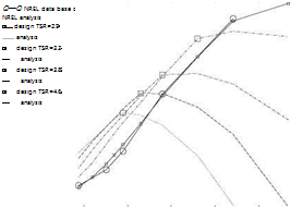
First, the analysis code has been used to predict the power captured by the NREL rotor for a range of TSR values and compare the theoretical results with the experi­mental measurements performed in the NASA Ames 80′ x 120′ wind tunnel [1]. The range in wind velocities is from 5 to 20m/s. The results are shown in Fig. 10.17, the large circles corresponding to the experiments and the small squares to the vortex model prediction. As can be seen, the model predicts the power coefficient accurately

Validation

Fig. 10.15 Viscous polar at Re = 500,000 and blade working conditions at TSR = 3.8

Validation

Fig. 10.16 Circulation and incidence distributions for the S809 blade at TSR = 3.8

for high TSR values, when the flow is attached, but for TSR < 3.3 much of the blade is stalled and the prediction becomes poor.

Secondly, for four values of the tip speed ratio, TSR = 2.9, 3.3, 3.8, 4.6, four rotors are designed with the optimization code each at the TSR and at the same CT coefficient corresponding to the value of the NREL rotor thrust on the tower. These results are shown as large squares in Fig. 10.17. In all cases the optimum rotor improves the power capture of the rotor by a significant amount. Then, for each of these rotors, the geometry has been kept fixed and the tip speed ratio varies to investigate off-design performance. The dotted lines in Fig. 10.17 show the results of this study. It is clear that the optimum rotor does not perform well at high TSR compared to the NREL rotor. However it must be noted that the power captured in that area is small and the benefit is really for low TSR’s, because the power increases proportionally to V3 and most of the energy resides in TSR < 3.3. It must be also

Подпись: 0.4
Validation
Validation

0 1 2 3 4 5 6 7

TSR

Fig. 10.17 Optimum rotors and analysis comparison with NREL rotor noted that rotor blades have a variable pitch that can be used to compensate for the change in wind speed, a feature that has not been used in this study.

The analysis code performs well and is efficient and reliable when the flow is attached. This is consistent with the results obtained with the Prandtl lifting line theory applied to wings of large aspect ratios. When significant amount of separation occurs on a blade, the results are no longer accurate. The viscous effects tend to introduce strong blade-wise gradients that are not predictable with a 2-D viscous polar and strip theory. Attempts have been made at modifying the polar to account for these effects, using the experimental data as a guide, but the results remain limited to the particular rotor and wind velocity to which the viscous polar have been tuned. A more productive approach is the hybrid method, to be described later, which consists in using aNavier-Stokes solver to capture the viscous effects in the blade near field and the vortex model for the far field and boundary conditions of the Navier-Stokes code.

Algorithm for High Incidences—Regularization of the Solution

In relation to Fig. 10.11, with decrease in TSR or equivalently with increase in adv, the incidence of the blade element increases. When a j > (a)Clmax, the sign of the lift slope changes to ‘a < 0, which destabilizes the algorithm. This simply reflects that multiple values of a exist for a given Cl, therefore it is necessary to regularize the solution to make it unique. This can be done by adding an artificial viscosity term to the right-hand-side:

1

Гj — —2qjcjCi(aj) + Mj(Гj+1 — 2rj + Гj-1); j — 2,…, jx — 1 (10.93)

Algorithm for High Incidences—Regularization of the Solution

where mj > 0 is the artificial viscosity coefficient. A test case with exact solution, based on the lifting line theory of Prandtl and a 2-D lift coefficient given analytically by Cl (a) — n sin 2a, for a wing with elliptic planform and equipped with a sym­metric profile, has shown that this approach gives excellent results for the complete range of a’s, from zero to § [12]. The artificial viscosity coefficient is given by

and the equation now reads

Подпись: ЛГ jcj dCij / yj _

1 + 2d~a l(1+uj)(Cj,] — Cj—1,]) — (adv+wj)(a;] — aj—1’] + aj,]7 + 2m

— —2 qjCjCi (aj) — rj + Mj (Г+ — 2Гп + Г”—1) (10.95)

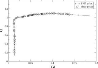
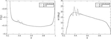
Now, the relaxation factor needs to be reduced to a value less than one, say ш — 0.3, depending on the polar smoothness. The need for the smoothing term is highlighted with a calculation of the two-bladed NREL rotor [1] at TSR — 3.8. The S809 profile that equips the blade is represented by the viscous polar calculated with XFOIL [13], for which one finds (a)Clmax — 17.5°. At this low TSR the blade is stalled from y — 0.35 to almost y — 0.6. The blade elements working conditions for the converged solution obtained with the artificial viscosity term are shown in Fig. 10.15 with the profile polar.

The circulation and incidence distributions, although converged for m — 0, show large oscillations which are unphysical, Fig. 10.16.

Analysis of the Flow Past a Given Rotor

In this section we consider the problem of calculating the flow past a given rotor. This is particularly useful to assess the performance of an optimum rotor at off-design conditions. Here, the blade sections will have variable working conditions in terms of a(y), with the possibility, on part of the blade, for the incidences to be larger than the incidence of maximum lift, i. e. a > (a)Clmax. In other words, part of the blade may be stalled. This will typically happen at small TSR’s.

10.5.1 Formulation

Analysis of the Flow Past a Given Rotor Подпись: (10.88)

With reference to Fig. 10.11, given a data set {CdVm, Cm, am} that characterizes the blade profile viscous polar, the governing equation simply reads

where a(y) = ф(у)—ї (y). The chord c( y) and twist t (y) distributions are given. The incoming velocity is q(y) = ^(1 + u(у))2 + (-3у – + w(y))2 and Г is the unknown circulation (Г < 0). In discrete form this reads

1

Г = – qjCjCi (a j), j = 2,…, jx – 1 (10.89)

Analysis of the Flow Past a Given Rotor
When a j < (a)Clmax, then <yCL > 0 and the simple, partial Newton linearization gives a converging algorithm

Auj and Awj are given by the induced velocity coefficients associated with Arj = Г]п+1 – Гj.

m is the relaxation factor and can be chosen up to m = 1.8. It is found that the coefficients aj, j – aj_i, j + aj, j < 0 and Cj, j – Cj_i, j > 0 so that the linearization contributions reinforce the diagonal of the iterative matrix underlying the relaxation method [11]. With jx = 101 this typically converges in a few hundreds of iterations.

Viscous Correction

The viscous effects are considered a small deviation of the inviscid solution at the design point. In particular, the design lift distribution along the blade is such that Cl(y) < Clmax. The viscous torque and viscous thrust coefficients, CTv and CTv are added to their inviscid counterparts. For one blade

Ctv = – q(У) y – + w(y)) Cdvc(y)ydy (10.80)

n y0 adv >

1 Г1

Подпись:Ctv = q(y)(1 + u(y)) Cdvc(y)dy

п У0

Viscous Correction Viscous Correction

In discrete form

where the 2-D viscous drag coefficient, Cdvk, is approximated locally by a parabola [10]. The viscous polar, Ci versus Cdv is obtained from experimental measurements or numerical simulation, as a data set {Cdvm, Clm, am} where m is the index corre­sponding to the а-sweep. The viscous drag is locally given by

Cdv(Cl) = (Cd0)m + (Cd 1 )mCl + (Cd2)mCf (10.84)

Подпись: CT1 + CTv1 + 2k(CT 2 + CTv2) CT 1 + CT v1 + 2K(CT 2 + CT v2) y Fig. 10.13 Circulation and induced velocity for optimum blade at TSR = 2.9 and CT = 0.205

The optimization proceeds along lines similar to the inviscid case. First an inviscid solution is obtained. Then the viscous correction is performed. к is defined as before, with Ct 1 replaced by Ct 1 + Ctv1, Ct2 by Ct2 + Ctv2 and CTtarget replaced by CTtarget – Ct0 and X reads

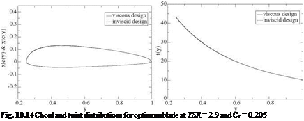
Подпись: Fig. 10.14 Chord and twist distributions for optimum blade at TSR = 2.9 and CT = 0.205

where the viscous contributions have been decomposed into 3 terms, independent, linear and quadratic functions of Г as

CTV = Ctv0 + Ctv1 + CTv2 (1°.86)

Ct v = Ct v0 + Ct v1 + Ct v2 (10.87)

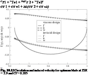
The inviscid and viscous distributions are compared in Figs. 10.13 and 10.14, for the TSR = 2.9 and CTtarget = 0.205. As can be seen, the effect of viscosity on the geometry is very small, however the efficiency drops 3.5% from n = 0.177 to П = 0.171.

Discretization

Подпись: aj,k or aj,k Discretization Подпись: (10.62)

The discrete formulation is now described. The influence coefficients are calculated as

Discretization

with the notation introduced earlier and in Fig. 10.10. The contributions to aj, k and Cjk of the vortex filament part that is beyond the Trefftz plane are approximated by the following remainders

Discretization

(10.64)

The torque and thrust coefficients are discretized as

jx 1

Подпись: (10.66)Ct = Гк (1 + Uk) yk (Пк – Пк-1)

Discretization

ТҐ

Each contributes to the minimization equation

д Ct 2 . .

щ = п + uj)yj (пj – пj-1)

jx-1

Подпись: к=2

+ п^Гк^-1, к – aj, к + aj, k)Уk (Пк – Пк-1), j = 2 ,jx – 1 (10.68) д С т 2 y j

Подпись: drj п adv—————- (о* + “’j)(пj- пj-1)

jx 1

Подпись: к=2

п^Гк c-1,к – Cj, к) (пк – Пк-1), j = 2,…, jx – 1 (10.69)

Подпись: d F (Г) drj Discretization Подпись: (10.70)

Boundary conditions complete the formulation with Г1 = rjx = 0 The minimization equation

Подпись: 2 [X (cj-1,k cj,k) Подпись: 'aj-1,j - aJ,J + aJ,j) УА j Discretization

is a linear, non-homogeneous system for the rj’s that can be solved by relaxation. Let Arj = Г”+1 – Г" be the change of circulation between iterations n and iteration n + 1, and ш the relaxation factor. The iterative process reads

Подпись: n j-1)_(i +uj)yj – X( adv + w j)]

jx 1

^ rk {(pj-1,k – aj, k + aj, k) yk – A (cj-1,k – cj,^] (Лк – Vk-1) (10.71)

k=2

With Jx = 101 and ш = 1.8 the solution converges in a few hundreds iterations. Note that if X = adv the system is homogeneous and the solution is rj = 0, Vj, which corresponds to zero loading of the rotor that rotates freely and does not disturb the flow. This is called “freewheeling”. For a given X the solution corresponds to a certain thrust. In order to find the value of the Lagrange multiplier that will correspond to the desired value of the thrust coefficient, say CTtarget, CT and CT are decomposed into linear and bilinear forms in terms of the rj’s

jx-1 jx-1

22

CT = CT1 + Ст2 = – X rjyj(nj-nj-1) + – x rJuJyj(nj – nj-1) (1°.72)

Подпись: j =2

Подпись: CT = CT 1 + CT 2 Discretization

j =2

(10.73)

CT1 and CT1 are homogeneous of degree one. CT2 and CT2 are homogeneous of degree two. Using the properties of homogeneous forms, the summation of the min­imization equations multiplied each by the corresponding rj results in the identity

DiscretizationCt 1 + 2Cr2 + X (Ct 1 + 2Ct2)

jx-1

= Г {(1 + 2uj)yj – x(Ov + 2wj)} (nj – nj-1) = 0 (10.74)

j =2

which is the discrete analog of the optimum condition derived earlier.

If one assumes that the optimum distributions of circulation for different CTtarget vary approximately by a multiplication factor, then knowing the solution rj for a particular value of X (say X = 0) allows to find a new value of the Lagrange multiplier as follows. Change the rj’s to new values k^. In order to satisfy the constraint one must have

Ct target = К Ct 1 + К 2Ct2 (10.75)

Подпись: К= Подпись: C^j + 4CT2CTtarget - CT 1 2CT 2 Подпись: (10.76)

Solving for к yields

The new estimate for X is obtained from the above identity as

Подпись: (10.77)CT1 + 2k CT 2

Ct 1 + 2k Ct 2

This procedure is repeated two or three times to produce the desired solution. Once the optimum circulation is obtained, the chord distribution is given by

where (Ci(a))opt corresponds to the point a on the polar such that Ci/Cd is maxi­mum. The twist distribution results from

Подпись: (10.79)tj = ф j a

Aerodynamic Design of a Rotor Blade—Betz Minimum Energy Condition

10.4.1 Formulation

The minimum energy condition of Betz [8] refers to the optimum conditions which lead to the minimum loss of energy in the slipstream. It applies equally to propellers and wind turbines. For the latter, the optimum distribution of circulation Г(y ) min­imizes the torque (negative) for a given thrust on the tower. The simple argument of Betz is that, in this case, an elementary force 8CT = —Г(y) (at – + w(y) dy should produce a constant elementary torque 8CT = ПГ(у) (1 + u(y)) ydy, inde­pendent of y. Hence the minimum energy condition of Betz reads

(1 + u (y)) y

y = y tanФ(у) = const. (10.43)

adv + w(y)

Aerodynamic Design of a Rotor Blade—Betz Minimum Energy Condition Подпись: f Г(y)w(y)dy Подпись: (10.44)

This is true only for vanishing circulation and induced velocities, as will be shown later. By analogy, lets consider the problem of the optimum wing loading in the Prandtl lifting line theory. Given that the lift and induced drag are

Подпись: w(y) Подпись: 1 Г1 Г '(n)d n 4n —1 y — n Подпись: (10.45)

where w(y) is the downwash (negative),

Munk [9] showed that, for the optimum loading, the downwash w has to be constant, else, moving a small element of lift (elementary horseshoe vortex) 8CL = 28Гdy from its current position yi to a position y2 such that 8w = w(y2) — w(y) > 0, would not change the total lift, yet would change the induced drag by 8CDt = —28Г8wdy < 0, a decrease in total drag, indicating that the distribution is not optimal. In other words, for an elementary 8CL = 2Гdy, the induced drag 8CDt = —2Г(у^(у^у should be independent of y, which implies that w(y) = const. A more mathematical proof consists in considering the objective function

F (Г) = Cot (Г) + XCl (Г) (10.46)

consisting of the induced drag to be minimized for a given lift, where X is the Lagrange multiplier. Taking the Frechet derivative yields the minimization equation that must hold for any change 8Г of circulation. The Frechet derivative can be defined as the limiting process

d F d

Подпись:(8 Г) = lim F (Г + в8Г)

д Г( ) в^0 d0y 2

The result is linear in 8 Г. It represents the derivative of F with respect to Г, in the direction of 8Г. Here we obtain:

d F l’1 ( dw l’1

— (8Г) = – 8^y)w(y) + Г(y) — (8Г) dy+2Xj 8Г(у)<іу (10.48)

But the kernel of w(Г) is antisymmetric. Hence, integration by part twice using the fact that Г(±1) = 8 Г(±1) = 0, yields the identity

Подпись: (10.49)dw

Г( y) (8 Г) = 8Г w( Г) d Г

Indeed, consider the second term in the integral above. By definition of the Frechet derivative of w(Г) in the direction 8 Г

Подпись:Подпись: I = -f1 dw f1 1 f1 8 Г'(Ш n

L Г( y)-(8 ndy = Г( y){ – -1 –Л )

I = _1 Ґ Ґ Г(y)8Г’Шndy 4n -1 -1 y – n

Aerodynamic Design of a Rotor Blade—Betz Minimum Energy Condition

A first integration by parts in n yields

Aerodynamic Design of a Rotor Blade—Betz Minimum Energy Condition

Again the integrated term vanishes and the second term, thanks to the antisym­metry of the kernel y-y, can be interpreted as

Подпись:d F f1

— (8Г) = -2j 8Г(y) (w(y) – X) dy, V8Г

The solution is simply w(y) = A. = const., as obtained by Munk with his simpler argument. The antisymmetry of the kernel simply indicates that two elementary horseshoe vortices of same intensity placed at y1 and y2 induce downwash that are opposite at the other horseshoe location. This is not the case with a wind turbine wake, because two vortices along the helix will have different shapes depending on their initial y-location at the blade, hence induce velocities u or w are not related. Let yv, zv be the equation of the vortex sheet of blade 1

Подпись:yv = n cos( adkx))

zv = n sin(шїщ)

A vortex filament corresponds to a fixed value of n. Two such vortices are shown in Fig. 10.10.

Aerodynamic Design of a Rotor Blade—Betz Minimum Energy Condition Aerodynamic Design of a Rotor Blade—Betz Minimum Energy Condition

The kernel for u and w does not have the antisymmetry property for the helicoidal vortex sheet as can be seen from the formulae

Подпись: 2X n Aerodynamic Design of a Rotor Blade—Betz Minimum Energy Condition Подпись: (10.60)

stating that the search is for minimum torque (negative) for a given thrust on the tower at a given tip speed ratio and blade root location y0. The minimization equation is derived for one blade as

The terms such as Г(у)дГ (&Г) cannot be transformed in this case, however, choosing 8Г = Г yields the following identity

J Г {(1 + 2u(y)) у – л(ayv + 2w(y^} dy = 0 (10.61)

y

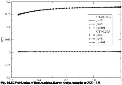
Подпись: Fig. 10.12 Verification of Betz condition for two design examples at TSR = 2.9
the interpretation of which is that the optimum solution satisfies the minimum energy condition of Betz, in the Trefftz plane, “in the average”, with Г as weighting factor. For a tip speed ratio TSR = 2.9, the design of a two bladed-rotor at (Cl )opt = 0.8979 with very light loading demonstrates that the minimum energy condition of Betz is verified. The thrust coefficient is CT = 0.0032, the corresponding value of the Lagrange multiplier is X = 0.3433 and the power coefficient Cp = 0.0031. For a higher loading, corresponding to the two-bladed NREL rotor at the same TSR and CT = 0.205, one finds X = 0.254 and Cp = 0.1768. The deviation from the Betz condition, e(y) = (y tan ф(у) – X)/X, is shown in Fig. 10.12. As can be seen, for lightly loaded rotor, the Betz condition is satisfied, but it is no longer the case when loading is more realistic.

Wake Equilibrium Condition

The power absorbed by the rotor is also estimated by using the torque evaluation and the speed of rotation as

P = tQ (10.40)

The vortex sheets are considered in “equilibrium” when the power absorbed by the rotor matches the power deficit Ws in the far wake obtained from actuator disk theory, i. e. with the current notation

P = tQ = 2npU3 R2(1 + u)2 u (10.41)

This is a cubic equation for the average axial induced velocity u at the rotor

2 Ct

4(1 + u)2u = TSRCt = — = Cp (10.42)

adv

The solution procedure consists in recalculating the solution with an updated vortex structure until it satisfies the equilibrium condition to acceptable accuracy (ACt/Ct | < 10-3).