Category Theoretical and Applied Aerodynamics

Three Dimensional Boundary Layers

Consider a flat wing, away from the tips, at zero angle of attack in incompressible flow. The boundary layer equations are

Подпись:du dv d w

Three Dimensional Boundary Layers Three Dimensional Boundary Layers Подпись: (8.154) (8.155)

dx + d y + dz

The same result can be found that ~ 0, hence the pressure is given by the inviscid flow solution.

The boundary conditions at the solid surface are u = v = w = 0.

At the outer edge of the boundary layer, u = ui and w = wi. The v-component at the edge carries the influence of the boundary layer on the inviscid flow. It is not known a priori and is part of the solution.

The initial condition, upstream of the wing is simply uniform flow u = UOT.

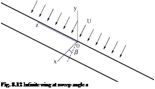
For infinite swept wings with the z-axis in the direction of span (Fig. 8.12)

Подпись:d p du dw

Подпись: Fig. 8.12 Infinite wing at sweep angle в

dz = dz = dz

hence, the boundary layer equations reduce to (p = const.)

Подпись:du dv

Подпись: du Подпись: dv Подпись: dp d2u dx + ‘d y2 Подпись: (8.158)

dx + d y ^

Подпись:dw dw d2w

pu dx + pv dy = ‘‘ay?

Note that u and v are independent of w, the so-called independence principle. This is true only for incompressible flow where p = const.

The general three-dimensional boundary layers are covered in Howarth [4] and Stewartson [6]

Finally, the sources of the fundamental materials in this section are reviewed. The analysis of the relative motion near a point is discussed by Batchelor [7].

The theory of boundary layer is covered in Schlichting [3], Rosenhead [8] and White [9].

Applications to low speed aerodynamics are discussed in Moran [10]. Compress­ible viscous flows are studied in Liepmann and Roshko [2] and in Stewartson [6].

Stability of viscous flows as well as transitional and turbulent flows are not covered here and the reader is referred to literature for these topics.

Von Karman Integral Momentum Equation

Consider first the flat plate and incompressible flow (no pressure gradient)

The conservation theorems applied to the control volume defined in Fig.8.8 give the

8.3.1 Flow at the Trailing Edge

For potential flow around a flat plate, the surface pressure distribution is given by

Von Karman Integral Momentum Equation(8.152)

hence, we expect the boundary layer response to this adverse pressure gradient near the trailing edge to result possibly in separation, since the pressure gradient is a forcing function in the momentum equation.

Even for a flat plate at zero angle of attack and ignoring the pressure gradient of the outer inviscid flow, at the trailing edge the skin friction is discontinuous as shown in Fig. 8.11.

The displacement thickness will have discontinuity in the derivative at the trailing edge. The inviscid pressure over the augmented body will not be regular in x.

Подпись: du x,0*° Подпись: du x,0)=0 dy Von Karman Integral Momentum Equation
Von Karman Integral Momentum Equation

More sophisticated treatment is required to account for separation, trailing edge singularity and curvature of the wake.

Fig. 8.11 Boundary layer in the vicinity of the trailing edge

Flow Past a Wedge (Falkner/Skan)

The inviscid solution is of the form U (x) = Cxm. The governing equation for the self-similar solution for the stream function reads

F"’ + FF” + в(1 – F’2) = 0 (8.85)

where в = mm is the wedge angle, and with boundary conditions

• at n = 0: F = F’ = 0,

• as n F’ ^ 1.

For more on this, we refer to Hartee numerical analysis and Stewartson analysis.

Special cases:

• Flat plate: m = 0, в = 0.

• Stagnation point: m = 1, в = 1.

When в < 0 (m < 0), separation occurs.

Blasius Solution for the Flat Plate (No Pressure Gradient)

Blasius Solution for the Flat Plate (No Pressure Gradient)

In incompressible flow, the self-similar solution due to Blasius is based on the idea that the u-velocity profile is of the form

where, as seen before, S(x) ~ , and n = Уф. If one introduces the stream

function ф(х, y) = US(x)F(n), the governing equation for F(n) is:

FF” + 2 F= 0 (8.79)

The boundary conditions are as follows

• at n = 0: F = F’ = 0,

• as n F’ ^ 1.

The numerical solution of Blasius yields the results

S(x) 5.0

x Rex

(8.80)

S*(x) 1.7203 x *fRTx

(8.81)

6(x) 0.664 x Rex

(8.82)

0.664

Cf(x) = vw;

(8.83)

1.328

Df VR*

(8.84)

Note that Co/ = 2Cf (l) = 26(l)/1.

Historical and Classical Works

The history of boundary layer is very rich and interesting. Starting from Prandtl’s original work (1904) and his student Blasius and von Karman and others (in the field of turbulent flows as well), the theory has developed over the years. Many researchers, all over the world, contributed to this subject. In Gottingen, Germany, where Prandtl worked, there was a conference in 2004, celebrating 100 years anniversary of bound­ary layer theory (the proceedings is published by Springer Verlag [5]).

In these notes, some topics will be discussed with historical remarks. Transforma­tions of subsonic boundary layer equations to the incompressible ones show that com­pressibility effects do not change the basic phenomena. Singularities at separation (and attachment) points as well as trailing edge show the limitation of boundary layer equations and the importance of coupling viscous and inviscid flows (as suggested by Prandtl himself through introducing the concept of displacement thickness). Treat­ment of separated flows is important for practical applications. Axisymmetric flow transformation to 2-D like equations (Mangler) and three dimensional flows over swept wings are also discussed.

Some of these works are of limited values today, thanks to the power of our computers. Nevertheless, it is still useful to study the ideas behind them.

Determination of Drag

If Pr = 1 (i. e. ЦCp = k), the energy equation in the boundary layer approximation becomes

Подпись:dT д d u2 d dH

д) + dy Ы2 = дУ (M4)

Determination of Drag Подпись: (8.65)

This simplified equation admits a solution H = HTO, provided the boundary conditions on the temperature is consistent with this solution:

At the wall u = 0, hence Tw = HTO/Cp; also,

Подпись:д T du д T

Cp + u = 0, at the wall |w = 0

d y d y d y

Determination of Drag Подпись: (8.67)

The energy equation is replaced by Bernoulli’s law inside the boundary layer:

where p = pi (x).

Assume that the undisturbed flow is aligned with the x-axis.

The drag per unit span, D’ can be obtained by direct integration of the stresses around the profile as

D = pdy + tw dx (8.68)

where (dx, dy) is a small element of the profile contour C.

From momentum balance applied to a large rectangle surrounding the profile, see Fig. 8.7. Contributions on control surfaces 3 and 4 vanish when the control volume is expanded far away and contributions on 1 and 2 can be combined, resulting in the drag being obtained as an integral across the far wake:

/

TO

pu(x, y)(U — u(x, y)) dy (8.69)

-TO

The drag can also be evaluated in terms of entropy (Oswatitsch formula [1]).

Assume Pr = 1 and H = H0. Using Crocco’s relation for viscous flows at the far wake:

– U = Tx + viscous term (8.70)

dy dy

Ignoring the last term for high Reynolds number flows in the wake, the above equation gives

Подпись: (8.71)– Uu = Txs + const.

Far from the wake, the flow returns to uniform conditions and the entropy to sx. Hence

U(U – u) = Tx(s – sx) (8.72)

The drag reads

T 00

D = U pu(s – sx)dy (8.73)

U – x

The work done by the drag D’U is related to the losses in terms of entropy.

In the case of a flat plate, the drag is simply the friction drag.

In the case of an airfoil, the drag is the sum of friction drag and pressure drag (due to separated flow).

8.2.5 Unsteady Boundary Layer

The unsteady boundary layer equations are given by

Подпись: (8.74) (8.75) Подпись:

Подпись: Fig. 8.7 Control volume for the evaluation of drag D'
Determination of Drag
Подпись: 4
Подпись: U
Подпись: 3

+ dfi = 0

dt dx dy

dpu du du dpui dui d

~df + pu dx + pv dy = ~dT + pui dX + dy

Determination of Drag

dpH


dH dH _ dpi d

dx + PV dy dt + dy


Determination of Drag

where p = pRT and p = p(T).

The boundary conditions at the solid wall (y = 0) are

Подпись: (8.77)u(x, 0) = uw(t), v(x, 0) = 0, T = Tw(x, t)

As a simple example of unsteady boundary layer, Liepmann and Roshko [2] dis­cuss the Rayleigh’s problem representing the diffusion of vorticity, see also Schlicht – ing [3] and Howarth [4].

Energy Equation for Compressible Viscous Flows

There are six types of energy important in our analysis (we exclude, chemical, elec­tromagnetic and nuclear energies):

Mechanical energy

Thermodynamic energy

Kinetic energy

Internal energy

Potential energy

Heat

—- Work done by pressure ^

—- Work done by friction ^

For inviscid flow, the Euler equations have the following energy balance:

Подпись:dpuH dpv H

dx + dy

where H = h + 2 (u2 + v2) + potential energy, and h = e + p. Here we have ignored heat and viscous dissipation.

Подпись: dpuH dpv H dx + dy Energy Equation for Compressible Viscous Flows Подпись: (8.55)

For the Navier-Stokes equations, the energy equation is

Подпись: (V .V.T ) Energy Equation for Compressible Viscous Flows Подпись: (8.56)

where k is the heat conductivity coefficient, and the viscous dissipation term is given by:

corresponding to the rate of work done by viscous forces.

Compressible Viscous Fluid Flow

5.2.1 Viscous Stresses and Constitutive Relations

For compressible flows, there is a second viscosity coefficient A. Stresses are related to strain rates as follows:

д и

ди

Dv

&1,1 = 2p + A Dx

Dx + д у

(8.48)

Dv

ди

Dv

V2,2 = 2p + A д у

Dx + д у

(8.49)

/

‘ди

Dv

(8.50)

&1,2 = &2,1 = U

чд x + д у

According to Stokes hypothesis: A = — 2p.

5.2.2 Navier-Stokes Equations for 2-D Compressible Flows

Assuming A and u are constant Conservation of mass:

дри Dpv Dx + ду 0

Conservation of x-momentum:

Подпись:Подпись: (8.53)du du dp (д2н d2u p (d2u d2v

pudX + pvdy = ~3x + p oX2 + + 3 dX2 + dXdy

Conservation of y-momentum:

dv dv dp (d2 v d2v p ( d2u d2v

pudX + pvdy = ~d + p oX2 + dy2 + 3 дХдУ + of2

The system is completed with the equation of energy for temperature T and the equation of state (for a perfect gas) p = pRT.

Boundary Layer Thicknesses

Let S*(x) denote the boundary layer displacement thickness. It is defined as the distance the wall should be displaced to compensate for the deficit of mass flow rate of the boundary layer compared to the local uniform inviscid flow Ui (x), see Fig. 8.6. Mathematically this means

Boundary Layer Thicknessesp(x, y)u(x, y)dy = Pi(x)ui(x) (S(x) — S*(x)) ^

Boundary Layer Thicknesses(8.44)

Note: the definition of displacement thickness is valid for compressible as well as incompressible flows. S* will be used in viscous/inviscid interaction.

Let 6(x) represent the boundary layer momentum thickness. It is related to the drag due to friction as Df = pi (x)U2(x)6(x).

As will be shown later, by application of control volume (CV ) theorems, the drag due to friction can be evaluated in terms of the velocity profile exiting the CV.

rS(x) rS(x)

Подпись: 0

— p(x, y)u2(x, y)dy + p(x, y)u(x, y)ui (x)dy = pi (x)u2(x)6(x) ^

or,

ejv = F p(x, y)u(x, у>/! – и(ЫЛ d y (8.46)

S(x) 0 Pi (x )«i (x) Ui (x) S(x)

Note: for incompressible flow: p = 1. Energy and enthalpy thicknesses can similarly be defined.

The skin friction coefficient is defined as

Boundary Layer Thicknesses

2 д (ul)

Rei D (?)


u—

Рд у


T


C


(8.47)


2 p™uiL


Boundary Layer Thicknesses

Boundary Layer Thicknesses