Category Theoretical and Applied Aerodynamics

Equilibrium of the Aggie Micro Flyer

The AMF has a span bm = 1m and a constant chord cxm = 0.192 m.

14.4.3.1 Main Wing

What is the wing aspect ratio, ARm?

Using the viscous polar of the Selig 1223 at Re = 200,000 with the “prandtline. f” code, it was found that the wing has a lift slope dCLm/da = 4.8701. Compare this result with the theoretical formula dCLm/da = 2n / (1 + 2/ARm).

14.4.3.2 Lift Curves

The linearized lift curve at low incidences for the main wing is: CLm = 4.8701a + 0.6997, and for the tail: CLt = 1.6338a + 3.4529tt – 0.26135, a and tt in radian.

Give the general formula for the lift CL (a, tt) of the combination of the wing and tail of areas Am and At, and reference area Aref = Am + At.

Application: check that with Am = 0.192 m2, At = 0.1525 m2, CL (a, tt) = 3.4374a + 1.5286tt + 0.2742.

14.4.3.3 Moment Curve

The moment coefficient for the complete airplane is given by: CM, o(a, tt) = -1.378a – 1.268tt – 0.03492.

Write the equilibrium equation for the aerodynamic moment (or equivalently write CM, cg = 0), given that xcg/lref = 0.3064. Neglect moment contribution from the engine.

Solve for aeq (tt).

Application: The maximum speed corresponding to full throttle and horizontal flight corresponds to tt = 1.63°. Find the angle of incidence aeq in deg.

Prandtl Lifting Line Theory

14.4.2.1 Vortex Sheet

Describe briefly the vortex sheet behind a finite wing with sharp trailing edge and explain whether the velocity components (u, v, w) have jumps and why.

14.4.2.2 Designing for Tip Vortices

In general, the wing loading is such that Г’ ^ as y ^ ±b/2, an indication of strong tip vortices.

Combine modes 1 and 3 to satisfy Г'(±b/2) = 0, given that the total lift is (CL)t-o at take-off.

Find A1 and A3 in terms of (CL)t-o and wing aspect ratio AR.

Sketch the corresponding distributions of circulation and downwash (Use sin 3t = sin t (4 cos21 – 1)).

Show that there is upwash near the wing tips.

14.4.2.3 Induced Drag

Calculate the induced drag and the gain/loss compared to the elliptic loading.

Supersonic Flow (M0 > 1, в = JM(2 — 1)

A thin airfoil with parabolic camber line d(x) = 4dmx (1 – x/c) is moving with Mach number M0 in a uniform atmosphere. The chord of the airfoil is c, dm = d/c = 0.086.

Pressure Distributions

Plot —C + and – C – versus x for this airfoil at a = 0. What is the corresponding lift coefficient Cl?

Lift and Moment Coefficients

Calculate the zero incidence moment coefficient (Cm, o) 0.

Give the values of the coefficients C; and Cm, o for the general case a = 0.

Equilibrium About an Axis

Calculate the moment Cm, D about an arbitrary point D along the chord and if the profile is allowed to rotate freely about point D, show that the equilibrium will be stable provided xD/c < 1/2 (neglect weight).

Give the equilibrium incidence, aeq in terms of xD.

Does aeq depend on Mach number?

2-D Inviscid, Linearized, Thin Airfoil Theories

14.4.1.1 Incompressible Flow (M0 = 0)

Thickness Effect

In Thin Airfoil theory, what type of singularity distribution is used to represent thickness?

Which forces and moment coefficients are not zero in the symmetric problem associated with thickness, Ci, Cm, o, and Cd?

Is the pressure coefficient Cp affected by thickness? Explain.

Camber Effect

The Selig 1223 has a mean camber line which is parabolic to a good approximation, and a relative camber dm = d/c = 0.086.

Write the expressions of C; and Cm, o in terms of a and dm (Use results derived in class).

Find the angle of zero lift, (a)Cl=0.

What are the values of the following coefficients in the linear expressions of the lift and moment curves:

dCl _ dCm, o „

~j 5 Cl07 5 Cm, o0

da da

Sketch the flow past the mean camber line at a = 0. Explain.

Equilibrium About an Axis

If a hinge is placed at the nose of the Selig 1223 and the profile is allowed to rotate freely about it, what would the equilibrium angle be in deg (neglect weight)?

Is the equilibrium stable? Why?

Where is the center of pressure at equilibrium?

Sketch the free-body diagram of the profile at equilibrium, including the reaction, Cr of the hinge.

Glider Equilibrium

Away from high lift, a linear model of the glider in terms of the angle of incidence a (deg) and tail setting angle tt (deg) is given by:

CL (a, tt) = 0.1a + 0.01tt + 0.7
CM,0(a, tt) = -0.02a — 0.01tt — 0.13

14.3.3.1 Definition

Give the definition of the aerodynamic center.

14.3.3.2 Aerodynamic Center

Find the location xac of the aerodynamic center, given that the reference length is lref = 1.5 m.

14.3.3.3 Moment at Aerodynamic Center

Derive CM, ac.

14.3.3.4 Moment at Center of Gravity

Derive CM, cg given a 4 % positive static margin.

Is the airplane statically stable? Explain.

14.3.3.5 Equilibrium

Derive the equilibrium incidence a(tt).

14.3 Problem 4

Lifting Line Theory (3-D Inviscid Flow)

14.3.2.1 Induced Drag in Cruise

Give the formula for the induced drag Di in (N), in terms of the wing efficiency e, the dynamic pressure 1 pV2, and the other geometric characteristics of the wing.

Give the equilibrium equation along the vertical axis during horizontal cruise in dimensional form (neglect the lift of the tail).

Eliminate CL between the two results and rewrite Di.

Application: calculate Di for V = 20 m/s, M = 24.7 kg and b = 4.877 m, e = 0.9 (use p = 1.225 kg/m3).

14.3.2.2 Turn

In order to turn, the airplane must roll about its longitudinal axis. This can be achieved by using the ailerons, small flaps located along the trailing edge of the wing. Assume that the wing loading in cruise is given by:

Г [у (t)] = 2UbA1 (sin t + ^ sin 3t) „

b, 0 < t < n

у (t) = — 2 cos t

What is the induced drag coefficient during cruise in terms of A1?

The turn will require to add the antisymmetric mode A2 sin 2t. Sketch mode 2.

14.3.2.3 Drag Penalty

Find the drag penalty associated with the turn by calculating Cdl, given that A2 = A1/3. D

Thin Airfoil Theory (2-D Inviscid Flow)

14.3.1.1 Incompressible Flow (M0 = 0)

A thin airfoil with parabolic camber line d {x) = 4d c {1 – x) is moving with velocity U in a uniform atmosphere of density p. The chord of the airfoil is c, d = 0-086. Give the expression of the Fourier coefficients A0, A1, A2,An, for this airfoil. What is the angle of adaptation or ideal angle of attack? Sketch the corresponding flow. How is the flow at the leading edge?

Calculate the incidence of zero lift, a0 in deg. Show that the moments Cm, o = Cm, a.c. in this case.

Estimate the upper limit of the weight (in N) that a wing of chord c = 0.368 m and span b = 4.877 m could lift at Ci = 2 if the 2-D solution were applicable at take-off velocity V = 10.5m/s (use p = 1.225kg/m3). What would the take-off mass be in kg?

14.3.1.2 Supersonic Linearized Theory (M0 > 1)

A biconvex profile of equation z = 2e| {1 – f) equips a fin moving through the air at M0 = 2 and a = 1°.

Calculate the wave drag coefficient {Cd)a=0 and give the formula for Cl (a) and Cd (a) in terms of a and calculate the values for the given incidence and for a 10 % thickness ratio e = 0.1.

Estimate the upper limit of the lift and drag forces (in N) on the fin if c = 0.1m, b = 0.2 m and V = 633 m/s at z = 6000 m altitude (pair = 0.657 kg/m3).

Airplane Longitudinal Equilibrium

14.2.3.1 Global Coefficients

The airplane has the following lift and moment coefficients in terms of the geometric angle of attack a (rd) and tail setting angle tt (rd):

CL(a, tt) = 3.88a + 0.5 + 0.481ft
Cm,0(a, tt) = -1.31a — 0.124 — 0.452tt

Find the location ^ of the aerodynamic center.

Find the location of the center of gravity, given a 4% static margin of stability.

Give the definition of the aerodynamic center.

Derive the expression for the moment about the aerodynamic center, CM, ac{tt) as a function of the tail setting angle.

14.2.3.2 Take-Off Conditions

Using the transfer of moment formula, derive the moment about the center of gravity,

CM, cg {a, tt).

Find the equilibrium conditions, aeq{tt) and CLeq{tt) for the airplane.

If the airplane take-off lift coefficient is {CL )t-o = 1 -44, find the tail setting angle that will be needed, and the corresponding value of {aeq )t-o.

14.2 Problem 3

Lifting Line Theory (3-D Inviscid Flow)

14.2.2.1 Flow Model

Which velocity components are continuous across the vortex sheet and why?

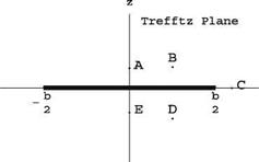
Sketch on your own sheet the velocity vectors at points A – E located near the vortex sheet in the Trefftz plane. See Fig. 14.1.

14.2.2.2 Improved Lift of a Rectangular Wing

The maximum lift of a rectangular wing is obtained when Г(y) = rmax. However, this solution corresponds to two vortices of strength rmax and – rmax shed by the left and right wing tips respectively, for which, as noted by Prandtl, the induced drag

Fig. 14.1 Sketch of vortex
sheet in the Trefftz plane

Lifting Line Theory (3-D Inviscid Flow)is infinite. A more desirable result is obtained by combining a few modes to improve the lift. Consider the following combination where only the odd modes, which are symmetric in y are used:

_ г [y (t)] = 2UbA1 (sin t + 1 sin 3t) 0 < t < n y (t) = — 2 cos t ’ _ _

Note that dr = ЩА cos31.

Find the value A1 such that the maximum circulation is equal to rmax, and sketch the distributions of circulation for the high lift wing and the elliptic loading.

Find the total lift CL in terms of aspect ratio AR, rmax, U and b. Compare with the maximum lift for the elliptic loading.

Find the downwash distribution wT (t) for the high lift wing and sketch it with the downwash for the elliptic loading.

14.2.2.3 Drag Penalty

Compute the induced drag of the high lift wing and compare it with the induced drag for the elliptic loading.

Problem 2

14.2.1 Thin Airfoil Theory (2-D Inviscid Flow)

14.2.1.1 Incompressible Flow (Mo = 0)

A thin airfoil with parabolic camber line d (x) = 4d c (1 – x) is moving with velocity U in a uniform atmosphere of density p. The chord of the airfoil is c.

Define the lift and moment coefficients, C; and Cm, o in terms of the dimensional quantities p, U, c, L, M, o, where L and M, o are the lift (N/m) and the moment (Nm/m) per unit span.

Use thin airfoil theory results to express the Ci and Cm, o in terms of a, the incidence angle (rd) and d the relative camber.

Given d = 0.086 find the angles of incidence in degree for which C; = 0.5, Ci = 2.0 and calculate the corresponding moments Cm, o.

Find the location of the center of pressure pp in both cases.

Show on a sketch the position of the center of pressure relative to the aerodynamic center.

14.2.1.2 Supersonic Linearized Theory (M0 > 1)

The same airfoil as in 1.1 is moving at supersonic speed.

Give the expression for the lift coefficient C; (a) in supersonic flow.

Give the expression for the moment coefficient Cm, o(a) in supersonic flow and

calculate (Cm, o)a=0.

Express x3L in terms of a.