Category Theoretical and Applied Aerodynamics

Hydraulic Analogy

The equations of unsteady two dimensional compressible inviscid flows are analo­gous to the shallow water equations where the height of the water corresponds to the density of the compressible fluid. To show such analogy, we will start with the isentropic Euler equations in conservative form

Подпись:Подпись:Hydraulic Analogy
+ dU + d-f. = о

dx dy

dpu dpu2 dpuv dp

dt + dx + dy dx

dpv dpuv dpv2 d p

dt + dx + dy dy

Hydraulic Analogy

P_

P0

The above equations imply conservation of mass, momentum and entropy. Energy is not conserved in general. Only for smooth flow, energy will be conserved.

Next, consider a thin layer of water over a flat smooth plate, where the height of the water is given by h (x, y, t).

Hydraulic Analogy Подпись: (13.23)

The conservation of mass requires

Since pw = const, it cancels out and the equation becomes similar to the com­pressible flow continuity equation, where p is replaced by h.

Hydraulic Analogy Подпись: dpwhuv d y Подпись: d h pw9h rn Подпись: 1 dh2 2 pw 9~dX Подпись: (13.24)

The momentum equations for the column of water with height h is given, ignoring the viscous effects, by

Подпись:dpwhuv dpwhuv dpwhv2 dh 1 dh2

+ + = —pwgh = — pw9

dt dx dy dy 2 dy

Once again, pw cancels out.

Assuming small variations of the water surface and ignoring the vertical acceler­ation, the pressure is governed by the hydrostatic equation

p = Patm + pw9(h — z), 0 < z < h (13.26)

where z is the elevation of a point above the flat plate.

Hence

On the other hand, from isentropic relation of compressible flows,

dp = dp d£ = 2 df_ dp = dp dp _ 2dL (13 28)

dx dp dx a dx ’ d y dp d y a d y ‘

where a2 = yRT. Hence the analogy holds if a2 corresponds to gh. In this case, the Mach number M = V/a corresponds to the Froude number F = V/л/gh of the shallow water waves where л/gh is the speed of surface waves due to small disturbances.

Notice the pressure of compressible flow corresponds to h2, hence the analogy holds only for y = 2. In this case the temperature of the compressible flow corre­sponds to h.

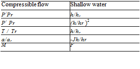
To summarize these relations, the different non dimensional quantities for com­pressible and shallow water flows are given in Table 13.1, where subscript r stands for reference quantities

Подпись: Table 13.1 Analog quantities for compressible flow and shallow water models Подпись: Compressible flow Shallow water P/Pr h/hr P/ Pr (h/hr )2 T / Tr h/hr a/ar -Jh/hr M F

There are several special cases of interest including

(i) Quasi-one dimensional unsteady flows in nozzles,

(ii) Two dimensional steady external and internal flows,

(iii) irrotational flows.

The above derivation shows that the analogy is valid for rotational flows where vorticity may be generated due to the variation of the total enthalpy according to Crocco’s relation. One can consider the special case where vorticity vanishes and a potential flow exists for both steady as well as unsteady phenomena. In all cases, the flow is assumed isentropic. In the following, hydraulic jumps (corresponding to shock relations of compressible flows) will be studied.

The propagation of sound corresponds to the propagation of an infinitesimal grav­ity wave, since

Подпись: Du ~Dt (13.29)

Hydraulic Analogy Подпись: (13.30)

corresponds to

with a2 = gh.

Подпись: d2 h dt2 Подпись: gh0V2h = 0 Подпись: (13.31)

Also, the linearization of the shallow water equation yields the classical wave equation

where a0 = gh0.

Real time observation is possible since g = 9.81 m/s2 and for h = 0.01 m, a = 0.3 m/s. In fact, shallow water experiment can be performed at the kitchen sink!

Подпись: P_ P0 Hydraulic Analogy Подпись: (13.32)

For smooth steady flows, one can obtain the isentropic relation and corresponding shallow water equations. For example

Supersonic (M > 1) and subsonic (M < 1) flows correspond to supercritical (F > 1) and subcritical (F < 1) flows.

The analogs of shock waves are called hydraulic jumps. Moving with the discon­tinuity and considering the relative normal velocity, one can derive the following steady relations

u 1 h 1 = u2h2 = m (13.33)

To evaluate the momentum balance, a control volume is used as shown in Fig. 13.3. Friction on the bottom surface is neglected.

The net acting force per unit span in the x-direction due to pressure is

J Pwg(h1 – z) dz – J Pwg(h2 – z) dz = 1 pwg (h2 – h^ (13.34)

Hence, the rate of change of x-momentum reads

Pwu2h2 – Pwu2h1 = 2Pwg ^2 – h^ (13.35)

or

u2hi + – ghf = uh2 + – gh2 = n (13.36)

The above equations can be solved for (u, h) = (u2, h2) given (u1, h 1) as follows uh = m, and u2h + 1 gh2 = n (13.37)

Hydraulic Analogy

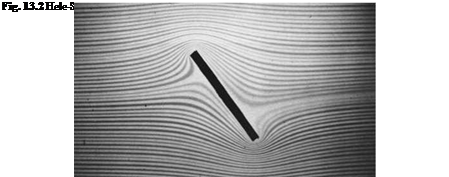
Fig. 13.3 Hele-Shaw flow past a rectangular block (from en. wikipedia. org)

Подпись:Hydraulic Analogy(13.44)

The solution with F1 < 1 and h/ h 1 < 1 is excluded. It corresponds to an expansion shock. To see that analogy, consider the specific energy (see White [7])

Подпись:

Подпись: h h 1
Подпись: -2 + 4 + 2 F2
Подпись: (13.43)

Подпись:Подпись: (13.42)

Hydraulic Analogy
Hydraulic Analogy
Подпись: The trivial root is h = h1, i.e. no jump. Other roots satisfy the relation
Подпись: 1 2 1 1 2 2 gh + 2 gh1 h + 2 ghi - n = 0
Подпись: Since Подпись: A solution of this quadratic equation is given by

1 2 1 m2

E = gh + 2 U = gh + 2 H2

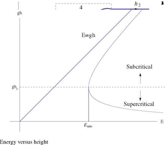
For a given m (discharge), there are two possible states for the same E, see the sketch in Fig. 13.4 and their relation is plotted in Fig. 13.5.

There is a minimum value of E at a certain value of h called the critical value. Setting dE/dh = 0, Emin occurs at g – m2/h3 = 0, or hc = [m2/g)1/3 and Emin = ghc + m2/(2hC).
Hydraulic Analogy

At the critical depth, m2 = ghl = c2h2, where c0 = Vghc and F = 1.

For E < Emi„, no solution exists and for E > Emin two solutions are possible with h > hc and u < co as well as h < hc and u > c0. The analogy with Mach waves is clear with the angle of the wave given by

sin g = — (13.46)

u

Подпись: E1 Подпись: (h2 - h1)3 E2 = g Подпись: (13.47)

Now, across the jump

This equation shows that dissipation loss is positive only if h2 > h 1, a requirement implied by the second law of thermodynamics.

A more consistent analysis would be based on the total enthalpy (and not just potential and kinetic energy)

h _ p/pr 1 1 u 2

Подпись:Подпись: (13.49)u2 ~ (Y – 1)p/Pr M2 + 2 Mr

The corresponding quantity for shallow water is

H _ h 1 1 / u 2

m2 hr F2 + 2 ur

The total enthalpy should decrease for steady isentropic Euler shocks (see [8]) and hence expansion shocks are excluded and the same is true for hydraulic jumps. Again, from the conservation of mass across the hydraulic jump

u і h і = u2h2 = m (13.50)

and from the momentum balance

2 19 9 19

u2h1 + gh2 = u2h2 + gh2 = n (13.51)

one can show, upon elimination of h that

1 Подпись: 11 M2 - M1 + gm 2 2 u2 Подпись: 0 (13.52)Hydraulic Analogy m2 1 m2

mu1 + g 2 = mu2 + g 2

2 u 21 2 u 22

Introducing the jump notation [a] = a2 – a1, one can write

< u > + gm = 0 (13.53)

Hydraulic Analogy

2 u2

Hence

Подпись: (13.55)Подпись: = — M1M2 = —gh<u>
T

M

The latter is analogous to the Prandtl relation for normal shock of compressible fluid flow.

Hydraulic analogy can provide experimental demonstration of compressible flow phenomena using a device called water table, which consists of an inexpensive sheet of glass with suitable sides. Either a model is moved in a thin layer of water or the
model is fixed and the water flows around it. The analogy is particularly useful for transonic flows including shocks. Examples are:

(i) Transonic flows in convergent/divergent nozzle at design and off-design con­ditions,

(ii) Steady two dimensional supersonic flows over airfoils (flat plate, parabolic or diamond airfoils). Compression shocks and expansion fans are easily identified. Attached and detached shocks as well as fish tail shocks can be observed, including wave reflected from the walls,

(iii) Unsteady flows, including accelerated and decelerated as well as oscillating airfoils.

There are limitations, of course. Strong shocks are not well represented. The assump­tions that vertical accelerations are small, the viscous force exerted by the horizontal bottom is negligible and the vertical variation of the velocity can be neglected in the continuity equation are questionable if quantitative results are required. In general, separated flows are not representative since the Reynolds numbers are very different in water and compressible flows. For more details, the reader is referred to Oswatitsch [9],Loh [10], Thompson [11] and White [7].

Flow Analogies

In this chapter we will discuss some experimental techniques for flow simulation and visualization, including the Hele-Shaw flow [1], shallow water, hydraulic analogy, electric analogy and analog computers. In each case, the theory and the limitation will be studied.

13.1 Hele-Shaw Flows

Consider a slow motion of fluid between two parallel plates separated by a small distance 2h. If a cylindrical body of arbitrary cross-section is inserted between the two plates at right angle, from wall to wall, the streamline pattern will be the same as that of potential flow around the same shape!

The creeping flow in general is dominated by viscous effects and inertia terms can be neglected leading to the Stokes equations for incompressible flows

Vp = pV2V and V. V = 0 (13.1)

The no slip and no penetration boundary conditions on the two walls are satisfied with V = 0.

Taking the divergence of the gradient of pressure yields the Laplacian equation, namely

V. (Vp) = V2p = pV. (V2v) = pV2 (V. V) = 0 (13.2)

Hence the pressure p(x, y, z) is a potential function.

Now, taking the rotational of the equation yields

Va (Vp) = 0 = pV2 (VaV) = pV2ш (13.3)

© Springer Science+Business Media Dordrecht 2015

J. J. Chattot and M. M. Hafez, Theoretical and Applied Aerodynamics,

DOI 10.1007/978-94-017-9825-9_13

Hence, the z-component of the rotational vector satisfies

Flow Analogies Flow Analogies

(13.4)


Flow Analogies

Moreover, for two dimensional flows, a stream function exists such that u = Фу and v = – фх, which satisfies

dv du

дх + d y z


V 2ф


(13.5)


Therefore, the governing equation for ф is

V4 ф = 0 (13.6)

the biharmonic equation.

Next, for a thin film of fluid, such that h < l, where l is a characteristic length (i. e. cylinder diameter), the above equations are further simplified, because of the strong gradient of the velocity in the normal z-direction. The governing equations become

Подпись:Подпись: (13.8)д p д2и д p d2v д p д2 w

дх – дz2 дy ^ дz2 дz ^ дz2

and

ди дv д w дх + д y + дz 0

with the condition that

Подпись: ReПодпись: << 1Flow Analogies(13.9)

Since w is much smaller than the (u, v) components, дp/дz is much smaller that the other components of the pressure gradient. Hence, to a first approximation p = p(x, y). The u and v components are obtained via integration in the z-direction and applying the no slip conditions at both z = ±h gives

u = – Т-дг(h2 – z2) (13.10)

2[л дх

Подпись: Tij Подпись: (13.12)
Flow Analogies

Notice that the ratio v/u does not depend on z, i. e. the direction of the flow and the streamline patterns are independent of z. Notice also, the stress tensor

is simplified to be

Tij = – pSij (13.13)

since the pressure magnitude is p = O (pUl/h2) and the tangential stresses are of order O (pU/h). Thus, in a thin film, the normal stresses are dominant. At the cylinder surface, with this model, only the tangency (no penetration) condition is satisfied and the no slip condition is not satisfied.

From the above results for u and v, upon elimination of the pressure, one obtains

Thus, the flow past a cylinder, at any given z, correspond to a 2-D irrotational flow past that cylinder.

Подпись: hence Flow Analogies Подпись: (13.15) (13.16) (13.17)

Notice the average velocity components are

where V and p depend only on x and y.

Therefore, a two-dimensional potential flow exists for which the potential function is proportional to the pressure. The above relation is of the same form as Darcy’s law for flows in porous media.

Applications in different fields can be found in a recent book by Gustafsson and Vasilev [2] on “Conformal and Potential Analysis in Hele-Shaw Cells.”

Hele-Shaw in 1898 used this analogy to obtain experimental patterns of stream­lines in potential flow about arbitrary 2-D bodies, by introducing coloring matter at a few points at the inlet section, for visual demonstration.

There are, however, some limitations. The circulation Г around any closed curve C lying in a (x, y)-plane, whether enclosing the cylinder or not, must be zero. This is clear from the definition

1 2 2 d p d p 1 2 2 d p

Г = udx + v dy = —- (h2 — z2) dx + dy = —- (h2 — z2) ds = 0

2^ dx dy 2p ds

(13.18)

since p is a single valued function of x and y.

Visualizations of potential flows in simply connected domains, for example, flow in a diffuser, are possible.

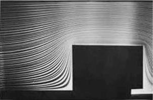
Ironically, potential streamlines are visualized using viscous dominated flows. beautiful pictures of Hele-Shaw flows past a circle, and inclined plate, a Rankine half-body, inclined airfoil, a rectangular block on a plate, uniform flow normal to a plate, can be found in Van Dyke’s Album of Fluid Motion [3]. Other pictures for flow past an ellipse and past symmetrical Joukowski airfoil at zero angle of attack can be found in Visualized Flow, compiled by the Japan Society of Mechanical Engineers. For more details of the theory, see Schlichting [4], Batchelor [5] and Acheson [6]. Two examples of Hele-Shaw flows are presented, the flow past a flat plate at high incidence and the flow past a rectangular block. In Fig. 13.1, the flat plate produces a flow that is antisymmetrical with respect to the plate center. Hence, the Kutta – Joukowski condition at the trailing edge is not satisfied and there is no circulation.

Flow Analogies

Fig. 13.1 NASA/Ames reeves electronic analog computer (1949) (from http://www. nasa. gov/ centers/ames/multimedia/images/2010/iotw/reeves. html)

The flow past a rectangular block is shown in Fig. 13.2. No visible separation occurs with the creeping flow regime.

Hele-Shaw flow and pattern formation in a time-dependent gap is studied in Ref. [3].

Hypersonic Vehicle Design

Townend [156] considered three applications:

(i) space launchers with reusable aerospace planes,

(ii) hypersonic airlines,

(iii) trans-atmospheric orbital transfer vehicles.

In all three applications, a central theme is integrating air-breathing propulsion into an aerodynamic design called “waverider”, a concept introduced by Nonweiler [157]. The idea is to generate three dimensional lifting bodies in high Mach number flows utilizing the streamlines behind a known shock wave.

It is well known that the maximum lift to drag ratio, (L/D)max, decreases as Mach number increases in the hypersonic regime, due to the strength of the shock wave. As an example is the dependence of L/D versus angel of attack for a flat plate, according to Newtonian flow theory. Accounting for laminar skin friction, (L/D)max is 6.5 for M0 = 10 and Re = 3.0 106. For a Boeing 707 cruising near Mach one, (L/D)max ~ 20. To generate higher L/D, waveriders are considered (see Anderson [9], Hayes and Probstein [2]).

Hypersonic Vehicle Design

Hypersonic Vehicle Design

Fig. 12.19 Nonweiler caret wing

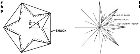
Inviscid flow solutions for star-shaped conical bodies using wedge solutions have been given by Maikapar [158] and Gonor [159]. See Fig. 12.18 for the cross section of the body and the shock system.

Such a design may have much less drag than a circular cone of the same cross section area.

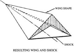
Nonweiler [157] and Peckham [160] have proposed delta wings of inverted V-shape, which can be considered as pieces of Maikapar’s shape.

The shock waves in Maikapar’s solution are weak. In Gonor’s solution, a straight weak shock is reflected from a plane of symmetry, in a regular manner and strikes the arm of the star.

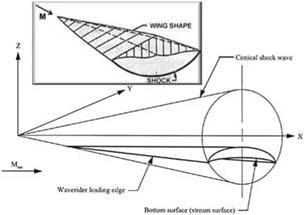
An example of Nonweiler wing and shock known as “caret wing” is shown in Fig. 12.19.

The flow over a cone at zero angle of attack can be used to generate waverider shapes. as done by Jones et al. [161]. See Fig. 12.20 constructed by Anderson [162].

Surveys on waveriders are given by Townend [156], Eggers et al. [163], Kuche – mann [18], Roe [164] and Koppenwwalter [165].

Hypersonic Vehicle Design

Fig. 12.20 Bodies supporting and containing parts of conical shock waves (from en. wikipedia. org)

Recently, Sobieczky et al. [166] introduced inverse aerodynamic design meth­ods to obtain more general shapes of waveriders from given shock waves. In this approach, a flow field bounded by a shock wave, a stream surface defining a solid body contour and an exit surface are calculated. For 2D inviscid supersonic flow, marching in the flow direction or normal to it are both possible. For three dimensional flows, cross marching is an ill-posed problem. However, axisymmetric equations can be used to approximate (to second order) locally three dimensional flows. Location of the axis of this “osculating” axisymmetric flow depends on local flow curvature and velocity gradient. The calculations can be made in a 2D meridian plane by the method of characteristics, however occurrence of limit surfaces (with multi-valued solution) requires initial data modification. Alternatively, the authors solved Euler equations in an inverse approach, guided by characteristic domain of dependence.

Rasmussen and Stevens [167] were able to use calculus of variations to optimize the waverider shapes utilizing the available analytical solutions and the associated properties of inviscid flow. In this regard, the reader is referred to the book on optimum aerodynamic shapes edited by Miele [168].

Recently, Cole [169] designed optimal conical wings in hypersonic flows based on Euler codes.

Long [170] studied the off design condition performance of hypersonic waveriders using Euler codes.

In the above works, skin friction drag is not included, hence the inviscid L/D is not reliable since the waveriders have large wetted surface areas. Anderson [9] introduced a family of waveriders called viscous-optimized hypersonic waveriders using CFD code and numerical optimization techniques. Comparison with wind tunnel tests are satisfactory. Their designs differ considerably in shape, depending on laminar to turbulent transition models. Anderson [9] considered also nonequilibrium chemistry on waverider aerodynamics. Nonweiler [157] raised the concern whether the sharp leading edges of waveriders can survive the heat flux without using active cooling. With the available new materials, the solid body conductivity and radiative cooling can indeed limit the temperature to acceptable levels.

Hypersonic Similitude

The inviscid hypersonic similitude was given first by Tsien [41] as discussed earlier. Based on the equivalence principle by Hayes [153], the similitude is applicable to general equations of state and three dimensional bodies. Hayes and Probstein [2], extended the similitude to take into account the interaction effect of the displacement thickness of the boundary layer and in this case, the total drag, including frictional drag, obeys the similarity law for the pressure drag. In viscous hypersonic similitude, the fluid is assumed however to be a perfect gas with additional assumptions on the dependence of the viscosity on temperature.

More recently, Viviand [154] studied the general similitude for the full Navier – Stokes equations for hypersonic flows involving high temperature real gas effects, whether in thermodynamic equilibrium or not, and showed that exact similitude is not possible in general. Viviand however introduced the concept of approximate similitude and applied it for simple models.

In the following the main important results of these studies are summarized.

A starting point is the Mach number Independence Principle by Oswatitsch [155]. In the case of a perfect gas, a limiting solution of the governing equations and boundary conditions is obtained as M0 approaches infinity. For a general fluid, the free stream density p0 and velocity U must be fixed and the quantities a0, p0, T0 and h0 approach zero. If M0 is sufficiently large, the solution behind the bow shock wave becomes independent of M0 and hence of p0 and T0. Hayes and Probstein [1] considered this principle is more than a similitude: “Two flows behind the bow shock waves, with different sufficiently high values of M0, are not merely similar but are essentially identical”.

The Mach Number Independence Principle, with p0 and U fixed applies to real fluids, including viscosity, heat conduction, relaxation, diffusion and rarefied gas effects. (For a perfect gas with constant y, the requirement that p0 and U be fixed can be relaxed provided the gas is inviscid). Hayes and Probstein [1] introduced the “Hypersonic Boundary Layer Independence” where they showed that the principal part of a hypersonic boundary layer, with given pressure and wall temperature distri­butions and free stream total enthalpy is independent of the external Mach number distribution outside the boundary layer. (The dependence upon Ms and ps appears only within a thin transitional layer at the outer edge of the boundary layer).

Again, the above principle is considered more than a similitude. The viscous hypersonic similitude was then developed taking into consideration the interaction between the displacement thickness distribution of the boundary layer and the exter­nal flow field. it is required that both the body and the displaced body are affinely related, hence

S* x

– = f (12.240)

t c U

Hayes and Probstein [1] concluded that x, the interaction parameter, must be invariant, where

X = Mlji: (12,241)

with c = jiwTo/(^oTw) and Re0 = poUl/^o.

The result for the surface pressure distribution is given, for two-dimensional flows, by

C = F(j’K’^Tk’-<’Pr) (12242)

The skin friction and heat transfer coefficient become

7 = G (7 – K-X H Y, Pr) <12,243)

C = H(j-K-x-hTTH–<-Pr) (12244)

Similarly, the total force coefficients CL/т2, CD/т3 as well as the pitching moment coefficient obey similar laws. (Notice, it is necessary that the base pres­sure follow the similarity law for the base pressure drag to follow the similarity law of the drag).

Formulas for both weak and strong viscous interactions, in terms of the parameter X, have been discussed earlier.

Hypersonic Area Rule

An interesting “area rule”, similar to transonic area rule, was introduced by Ladyzhenskii [150]. Following the discussion of Hayes and Probstein [2] and of Cheng [151], Ladyzhenskii showed that two slender bodies with blunt noses will have the same axial pressure distributions and the same drag under the following conditions:

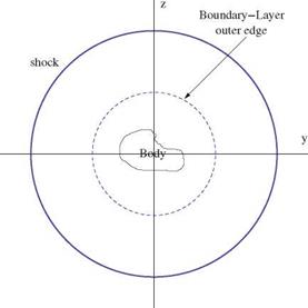
(i)

Подпись: Fig. 12.17 A sketch in the transverse plane illustrating the concept of equivalent body of revolution
Hypersonic Area Rule

the drag due to the blunt nose is the same for the two bodies,

(ii) the equivalent body will be within the entropy layer,

(iii) the cross section distribution is smooth.

Other variant requires the nose parts of equivalent bodies to have the same shape. The analysis is based on the assumption that the transverse pressure gradients in the entropy layer may be neglected for slender bodies with blunt noses and asymmetric shapes or at small angle of attack. It follows that the outer field must be (almost) axisymmetric.

A stronger form was discussed by Cheng [151], where only a limited part of the entropy layer is affected by the asymmetric after body (see Fig. 12.17).

Ladyzhenskii treated another type of area rule based on the assumption that є = (Y – 1)/(Y + 1) « 1.

The rule is based on Chernyi’s formulation for M0 = <x>, where the pressure is constant across the entire shock layer. Experiments carried out by Krasovskii [152] to correlate the drag of equivalent bodies indicated that blunting can indeed lower the drag slightly (compared to sharp cones), while the yawed body data showed a reduction in lift as large as 60 % for M0 = 18 and Re = 106.

Strictly speaking, the rule implies no lift and no moment. Indeed, slender bodies at hypersonic speeds suffer from a serious aerodynamic control problem.

Theoretical Developments

For the case of a flat plate, approximate analytical results are available for both weak and strong interaction (excluding the neighborhood of the leading edge).

Подпись: 6* ~ Theoretical Developments Подпись: w Подпись: (12.229)
Theoretical Developments

Following Hayes and Probstein [1] and Cox and Crabtree [3], the displacement thickness for weak interaction on a flat plate is given by (as discussed before)

Подпись: d 6* dx Theoretical Developments Подпись: (12.230)

Thus, the equivalent body slope due to the displacement effect is

where Rex = poUx/^o.

Подпись: p = 1 . Y(Y_ P0 4 Подпись: — K 2 + Y K2 Theoretical Developments Подпись: (12.231)

On the other hand, the pressure ratio for oblique shocks is

where K = M0 d6*/dx.

For (M0 d6*/dx)2 ^ 1, the pressure ratio over a wedge is obtained from

p d6* Ye ( Tw

— = 1 + YM0 = 1 + 0.664 + 1.73—W x (12.232)

P0 dx 2 Te

where x = M03VC/V Rex.

Подпись: P0 Подпись: 1 + 0.28x, for insulated wall 1 + 0.078x, for cold wall Подпись: (12.233)

For an insulated surface (Tw/T0 ^ 1) and a very cold wall (Tw/T0 ^ 0), the above results are reduced to

In the case of strong interaction, the pressure formula is based on strong oblique

shock, i. e.

Подпись:Theoretical DevelopmentsПодпись: P_ P0 (12.234)

It can be shown that for a consistent solution, the displacement thickness and induced pressure distribution must comply to the following behaviors, S* ~ x-3/4, p ~ x-1/2.

Подпись: S* ~ e ^0.664 + 1.73 Theoretical Developments Подпись: 3/4 Подпись: (12.235)
Theoretical Developments

Let p/p0 ~ kx-1/2, then

Theoretical Developments Theoretical Developments Theoretical Developments

Hence

Подпись: and Theoretical Developments Theoretical Developments

Therefore

The role of parameter x is clear for both interaction regions.

Comparison with experimental results are reasonable (see Hayes and Probstein [1]).

Later, a more comprehensive theory has been developed based on a triple deck structure, see reviews by Stewartson [145], Rothmayer and Smith [146], Sychev [147] and Brown et al. [148]. In this theory, upstream influence (suggested earlier by Lighthill [149]) as well as flow reversal and separation are studied in details.

Strong Viscous/Inviscid Interaction

Lee and Cheng [138] obtained a uniformly valid solution for hypersonic strong interaction problem including the second order boundary layer correction due to the uneven heating and external vorticity created by the curved leading edge shock wave. In general, there exist between the inviscid region and the boundary layer an intermediate transitional layer as demonstrated by Bush [139]. Near the leading edge, the problem is more complicated because of the slip velocity and the temperature jump in the wall boundary condition.

Strong Viscous/Inviscid Interaction Подпись: (12.218) (12.219) (12.219) (12.221)
Strong Viscous/Inviscid Interaction

Cheng and Novack [140] introduced a set of composite equations, with proper boundary conditions, to solve such problems numerically. The equations are the conservation of mass, tangential momentum and energy. In the latter two equations, the second order derivatives in the tangential direction are ignored. An approximate version of the normal momentum equation is used as follows

Cheng used a Crank-Nicolson scheme to obtain a numerical solution for attached flow over a flat plate, marching in the flow direction, on a relatively fine mesh (Ax/1 = 0.005 and Ay/5 = 0.01).

Cheng solve also blunt body problem with a similar set of equations in body fitted coordinates, where the transverse momentum equation is replaced by

d – = – Kc pu2 (12.222)

d y

where Kc is the longitudinal curvature of a reference surface.

Rudman and Rubin [141] and Rubin and Khosla [142] used similar formulations where they treated dp/дx term as a higher order term.

It is instructive to study the type of this set of equations. Following Vigneron et al. [143] and also Ref. [35], the streamwise pressure gradient дp/dx is multiplied by a coefficient ш.

For inviscid flows and w = 1, the equations are hyperbolic provided u2 = v2 > a2 and space marching is feasible. For 0 < w < 1, the equations are hyperbolic even in subsonic region provided

Подпись:(12.223)

where Mx = u/a.

For viscous flows, ignoring the first derivative in y, the conditions that the equa­tions are parabolic are

u > 0 and w < 2 (12.224)

– 1 + (y – 1) M2 У ’

hence, the so called parabolized Navier-Stokes (PNS) equations can be marched only for attached flows and with a fraction of the streamwise pressure gradient. However, w ^ 0 near the wall where Mx = 0. Lubard and Helliwell [144] showed that with backward difference approximation of dp/дx, there is a minimum Ax to be used for stability based of Fourier analysis and using finer meshes is not possible. See also Golovachov [39].

Strong Viscous/Inviscid Interaction Strong Viscous/Inviscid Interaction Strong Viscous/Inviscid Interaction

The question about the type of the PNS equations can be clearly seen in terms of velocity/vorticity formulation. Let

The vorticity equation can be marched since it is a convection/diffusion/reaction equation, however, the streamfunction equation is of mixed elliptic/hyperbolic type. In the outer inviscid supersonic flow, it is hyperbolic while near the solid surface, the speed is low and the equation is of elliptic type allowing for upstream influence and reversal flow. In boundary layer approximation, the streamline curvature term is ignored and the stream function equation becomes

Подпись:д 1 дф д у рд у w

and the system is of parabolic type. Therefore, it can be marched in space for attached flows. Couplings of Euler and parabolic equations are covered in Chap. 9.

To complete the formulation, the energy equation is solved for H or T and the pressure is calculated using the normal momentum equation in some form. The density is then calculated from the perfect gas law or its generalization.

It seems that marching the locally elliptic equation is a formidable task which appears in different forms in hypersonic flow research.

There are many attempts in the literature to use PNS with local separated regions using iterations locally. The obvious strategy is to use unsteady formulation to reach a steady state solution. Of course, such an option is more expensive.

Weak Viscous/Inviscid Interactions

The standard boundary layer theory does not take into account normal gradients outside the boundary layer. A higher order boundary layer theory was developed by Van Dyke in [135]. The first order outer region equations are the standard Euler equations for inviscid flows, while the first order inner region equations are the standard boundary layer equations. The second order outer region equations are the linearized Euler equations, while the second order inner region equations are linear perturbation of the boundary layer equations with several source terms.

Because of linearity, the boundary conditions and the source terms can be split to different second order effects including curvature terms, displacement, entropy and total enthalpy gradients. Notice, the second order external flow is affected by the displacement of the first order boundary layer. The inner and outer solutions must match and a single composite formula valid in the whole domain can be obtained.

Recently, Cousteix developed a hypersonic interaction theory based on the defect approach [136]. (The defect approach was developed by Le Balleur for transonic flows). Cousteix used in the inner region the difference between the physical variables and the external solutions. In the outer region, the defect variables vanish and the equations for the outer flow region are identical to Van Dyke’s. The equations in the inner region are different. For example, the pressure in the first order boundary layer varies and is equal to the local inviscid flow pressure.

In the defect approach, better matching is obtained between the inner and outer solutions than in Van Dyke’s method, at the expense of calculating the inviscid flow on the boundary layer grid.

Successful applications of Euler/boundary layer coupling via defect approach were reported by Monnoyer [137] who demonstrated that proper accounting for entropy and vorticity variations in the inviscid flow outer region is an important aspect of hypersonic flow simulations.

Solutions of Laminar Boundary Layer Equations at Hypersonic Speeds

Following Lees [131], Hayes and Probstein [1] and Cheng [132], the boundary layer equations are rewritten in terms of Howarth-Dorodnitsyn variables

Подпись: Є = fxc P dx, J0 Pe Подпись: y P dy 0 pe Solutions of Laminar Boundary Layer Equations at Hypersonic Speeds(12.205)

Подпись: (12.206)

Подпись: d3 f d 2 f 2 If3 + fdf = Cf1, Подпись: d 2 g d g and 2 2 + f = 0 a n2 d n

where Re = peuel/pe and p/p0 = cT/T0. Assuming Pr = 1, one obtains

where e = (y – 1)/(y + 1). f is a reduced streamfunction such that df /dn = u/ue and g = (H — Hw)/(He — Hw). h consists of terms including J0x pdx.

Подпись: f Подпись: = g = 0, at n = 0 d n Подпись: (12.207) (12.208)

The boundary conditions are

Therefore, for small e, there is a similar solution governed by Blasius equation and in this case, g = df/dg.

If terms of order є are retained, solutions for heat transfer rate, skin friction and displacement thickness can be written explicitly in terms of pressure distribution. The results of this analysis, called local similarity, are given in terms of a nondimensional parameter x which depends on M0 and Re (which is called the hypersonic viscous interaction parameter)

Подпись:Solutions of Laminar Boundary Layer Equations at Hypersonic Speeds(12.209)

The Stanton number and skin friction coefficients based on the edge conditions

are i/2

M3 St ~ 0.332^ (12.210)

Cf ~ 2St (12.211)

Mo у ~ є ^0.664 + 1.73 T j x Ц* f-dxj (f j (12.212)

Notice that S* ~ S.

Hayes and Probstein [1] reviewed similar solutions of boundary layers with chemi­cal reactions including constant pressure solutions, stagnation point solutions, locally similar solutions with Pr = 1. Discussions of local similarity concepts can be found in [1] as well as in the work of Moore [133].

We will consider next the integral methods, where the profiles of the unknown functions are assumed and hence the partial differential equations are reduced to ordinary differential equations. The integrated momentum and energy equations give an estimate of the x-dependence of the boundary layer solutions and indicate when the local similarity concept breaks down.

Following Shapiro [129] and Schlichting [130], the integral momentum equation is given by

Подпись: d fSd Ґ t 2 2 d Г

— Peue – pu dy – щ— (peue – pu) dy = rw (12.213) or, in terms of displacement thickness S* and momentum thickness в, the above equation becomes

1 d S* due tw

Подпись: pe u2 dxПодпись: Peue2Pe u2e) + – = – w (12.214)

ue dx

Подпись: d dx Подпись: fS pu Hdy 0 Подпись: — qw Подпись: (12.215)
Solutions of Laminar Boundary Layer Equations at Hypersonic Speeds

The integral energy equation is given by

or, in terms of the enthalpy thickness for He = const.

d 6 h qw

Подпись: (12.216)

Подпись: where Подпись: (12.217)
Solutions of Laminar Boundary Layer Equations at Hypersonic Speeds

dx pe UgHg

To avoid assuming the profiles of unknown functions, numerical solutions of the boundary layer equations can be obtained using finite difference methods. Appli­cations to hypersonic flows, with and without chemical reactions are reported by Blottner [134].

Navier-Stokes Equations

Writing the conservation laws of mass, momentum and energy including the vis­cous and heat conduction effects, in nondimensional form, reveals the following nondimensional parameters (see White [126]), 7, M0, Re, Pr, St, where

U p0Ul nCp fl

M0 = , Re = — , Pr = p, St = (12.180)

a.0 P0 k U

In the above formulas, k is the heat conductivity which is assumed to be propor­tional to p, and f is the characteristic frequency of unsteady motion. For reference quantities, a characteristic length of the body, l, free stream velocity U and density p0 are used.

There is one more nondimensional parameter defined as Da = tc/tm. The Damkohler number Da is the ratio of the characteristic time to establish chemi­cal equilibrium to the characteristic time of motion, tm = l/U. Da is very small for

Navier-Stokes Equations

chemical equilibrium and very large for frozen chemistry, while it is of order one for finite rate chemistry.

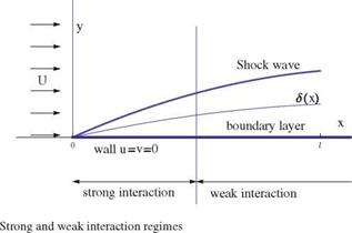
Under all the assumptions mentioned above, consider a flat plate in hypersonic flow (but with finite, not even very high Mach number) and assume laminar boundary layer with two regimes, strong and weak interactions as shown in Fig. 12.15.

Across the shock wave, kinetic energy is transformed into enthalpy and the result is high internal energy flow. Since the total enthalpy is constant across the shock, the downstream state is related to the upstream, undisturbed state by

1 2 1 2

H = h0 + – U2 = h + – У2 (12.181)

For hypersonic flows, У ^ U and h0 ^ h, then h ~ U2/2.

Подпись: 1 2 AT Cp AT =- U2, or p 2 ’ T0 Подпись: 1 U2 2 CpT0 Navier-Stokes Equations Подпись: (12.182)

Using the space shuttle as an example (Cousteix et al. [27]), let U = 7.6 km/s, the temperature for a perfect gas would be T = 29,000 K! In reality, some of the energy is stored in the form of chemical energy in the process of dissociation and for real gas T = 6,000 K instead. Even for U = 2 km/s, corresponding to M0 = 6 (assuming Cp ~ 1 KJ/kg ■ deg), the adiabatic compression leads to a high value AT ~ 2,273 K, where

A considerable part of the heat is transported to the vehicle surface (if radiation is neglected).

In the flowing, the thermal boundary layer will be discussed for both isothermal and insulated (adiabatic) walls.

12.3.1 Laminar Boundary Layer in Weak Interaction Regime

For high Reynolds numbers, the viscous effects are confined to a layer next to the wall, of thickness S ^ l, and inside such a layer v ^ u. Based on order of magnitude analysis, the pressure does not vary across the boundary layer, hence the governing equations in two dimensions are (see Hayes and Probstein [127])

дpu дум дх + дy 0

(12.183)

дpu2 дрuv дp д дх + д y дх + д y

дu

(12.184)

^д y

др^,Н дpv Н д ( д T д ( дх + дy дy дy + дy ^

д^ /2

(12.185)

д y

where

1 2

u

2

p = pRT, and Н = CpT +

(12.186)

The energy equation can also be written in the form

( дT дT дp д ( дT (дu2

pCp Гдх +v —y) = ’‘Ш + ~y Vat) + )

(12.187)

see Liepmann and Roshko [128], Shapiro [129] and Schlichting [130]. The pressure gradient is determined by the external flow

Подпись: (12.188)dp d Ug dTe

— = ~peue~ = peCp —

dx dx dx

Since dp/дy ~ 0, the temperature and density are related and satisfy the relation

Подпись: (12.189)pT = peTe

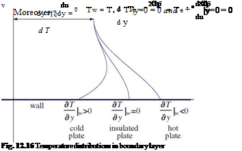
The wall boundary conditions are u = v = 0. Either Tw or дT/дy is specified at the wall. the thermal boundary layer is shown in Fig. 12.16.

Notice (дT/дy)y=0 > 0 for cold plate and (дT/дy)y=0 < 0 for hot plate.

The energy equation can be rewritten in terms of Pr (assuming Cp is constant)

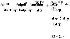
Подпись:дриН дpvH _ д ґ дH д // 1 дT

дх + ду ду ^ ду + дy Pr ду

For Pr = 1, the above equation admits a solution H = CpTs = CpT + u2/2 = const where the subscript s stands for stagnation.

Navier-Stokes Equations Navier-Stokes Equations

Since u = 0 at the wall, it follows that the wall temperature is constant and equal to the stagnation temperature, i. e.

The temperature profile is given by

Подпись: (12.193)

Подпись: and Подпись: Tw = Te( 1 + ^ Подпись: (12.194)

T = Te + lk (u2 – u2)

Navier-Stokes Equations Подпись: (12.195)

Notice that the stagnation temperature can be constant throughout the boundary layer only if the heat transfer is balanced by the work of viscous stresses or

therefore H is constant only when Pr = 1.

For the case of the flat plate, dp/dx = 0, a particular solution of the energy equation is H = u since the energy equation reduces to the momentum equation. More generally, let H = a + bu. To find a and b, we impose the boundary conditions u = 0 and T = Tw at y = 0 and T = Te and u = ue at the edge of the boundary layer. Thus the relation between u and T inside the boundary layer is given by

Подпись:12 12 u

CpT + u = CpTw + Cp (Te — Tw) + ue

2 2 ue

Navier-Stokes Equations

Now, the heat transfer and skin friction at the wall are given by

or, in terms of wall properties

Cf w

Ch w = f Rew (12.203)

If Pr = 1, it is conventional to define the adiabatic wall temperature as

Ta = Te(1 + r l-1 M^ (12.204)

For laminar flow, r ~ fPr as demonstrated by Schlichting [130]. r is called the recovery factor and it represents the ratio of the frictional temperature increase of the plate to that due to adiabatic compression.