Category Aerodynamics of V/STOL Flight

Helicopter Performance

Methods can now be developed for calculating the various performance items of a helicopter:

1. The maximum speed Fmax.

2. Cruising speed.

3. Absolute ceiling.

4. Service ceiling.

5. Forward rate-of-climb.

6. Hover ceiling IGE (in-ground-effect).

7. Hover ceiling OGE (out-of-ground-effect).

8. Fuel consumption.

9. Range.

10. Vertical rate-of-climb.

11. Time-to-climb.

The calculation of these items, except for hover and vertical performance, is similar to the procedure followed for fixed-wing aircraft. The first step in the calculation of the forward flight performance is to determine the power required and the power available as a function of forward speed for various altitudes. The calculation of the power required proceeds according to the methods just presented. The determination of the power available follows from the engine specifications furnished by the engine manufacturer. In addition, however, suitable allowance must be made for the various losses associated with the engine installation in the helicopter:

1. Duct losses.

2. Cooling power.

3. Accessory power.

4. Transmission losses.

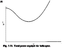
Power Required. The required power is the sum of three parts: (1) the induced power, (2) the profile power, and (3) the parasite power. The induced power varies inversely with V at the higher speeds. The parasite power varies directly with the cube of the forward speed, and the profile power increases only slightly with the square of the forward speed over that required in hover. Qualitatively, the power breakdown in forward flight is shown in Fig. 5-30.

The total power required, therefore, has the form represented in Fig. 5-31.

Helicopter Performance Подпись: (5-53)

At the lower speeds the power required decreases with increasing V because of the drop-off in the induced power. However, the parasite power increases with V3 so that the speed reached corresponds to the minimum power required at which an increase in V results in an increase in the parasite power greater than the decrease in the induced power. The value of the velocity, Fopt, corresponding to the minimum power, can be found approximately by writing the power required as

This equation assumes that the variation of the profile power with V is

Подпись: W2 2 pAVm Helicopter Performance

negligible. By differentiating (5-53) with respect to V and equating it to zero we obtain

or

P = 3 P

x 1 x n
Helicopter Performance Подпись: (5-54)

Thus it can be seen that at minimum power the induced power is approxi­mately three times the parasite power. This result is identical to that given in many texts for fixed-wing aircraft. Solution of the above equation for V0J)l results in

A little contemplation of (5-54) reveals several interesting facts. First, because most helicopters employ approximately the same disk loading and A/f is a dimensionless geometric ratio that is nearly constant from one helicopter to the next, the speed Vopi for minimum power would be expected to be nearly the same for all helicopters. At sea level Vopt is usually of* the order of 60 to 70 knots. Second, it can be seen that Fopt increases as / decreases, that is, as the aerodynamic cleanliness of the helicopter is im­proved. Third, Fopt is seen to increase with increasing disk loading. Finally, Vopt increases with increasing altitude as the density decreases. Because the power available for a helicopter is independent of forward speed, it will be shown later that Vopt is the forward speed that results in the best rate of climb.

Parasite Drag. The parasite drag is important to the operation of a helicopter. This statement is somewhat paradoxical in view of the fact that the helicopter is a slow-speed aircraft and that its chief virtue lies in its VTOL capabilities. Nevertheless, the majority of the missions for which helicopters are employed favors the machine with the best range. Army missions are concerned with the radius of action of the helicopter in deliver­ing troops and supplies. Navy missions are concerned with the radius of action in the performance of ASW (antisubmarine warfare) or rescue missions. Commercial operators, of course, are concerned with drag because its reduction results in a corresponding saving in fuel, which, over the year, can represent a considerable expenditure.

Power Available. Power available is defined here as the power supplied directly to the rotors after the various losses have been removed. It excludes power to any antitorque tail rotor, which is considered to be part of the power required. The determination of the power available is obtained by the use of the engine specifications furnished by the manufacturer.

The power from the engine is delivered to the rotors by a system of shafts and transmissions through which certain losses occur. Although a certain amount of the power lost in a transmission is independent of the transmitted power, being more a function of the rpm, it is common practice to assume a percentage loss in the transmitted power. A figure of 1% per gear mesh is representative of this loss.

In addition to the transmission losses, a penalty may be incurred in the power in order to cool the engine. This loss will vary greatly from one instal­lation to another, depending on the cooling system design. To have some appreciation of the magnitude of this loss, it is stated here simply that for one particular installation of which I have knowledge this loss is of the order of 2.5% of the engine power.

Still another loss in the engine power of reciprocating engines is incurred because of the losses in total pressure in the carburetor inlet ducting and increases in the back pressure produced by exhaust stacks and ducts. Again, this loss depends on the design of the particular configuration; in general, however, it is of the order of 1 or 2% of the engine power output. Finally, an increment must be subtracted for the power required by accessories such as the generator or alternators.

Thus the power available to the rotors can be 4 to 8% less than that delivered by the engine or engines.

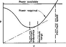
Power Required and Power Available. A typical variation of power required and power available as a function of speed for a given altitude and gross weight is shown in Fig. 5-32.

Of course, there are different definitions of power available, by which is meant, specifically, normal rated power and military power (or takeoff power). Normal rated power is the continuous power rating of the engine and is usually the one of most concern. There are two immediate observa­tions to be made from Fig. 5-32. The first is the maximum forward speed Fmax which is determined by the intersection of the power-available curve with the power-required curve. It is, of course, the power-limited Fmax. It is entirely possible, as already discussed, that the maximum speed may be limited by the onset of retreating blade stall or compressibility effects which produce excessive vibration levels.

The second point to be observed in Fig. 5-32 is the velocity V2 that corresponds to the minimum power required. This forward speed is obviously the best forward speed for maximum endurance, for the rate of fuel consumption in steady flight is proportional to the power required.

Cruising Speed for Maximum Range. The brake specific fuel consumption varies slightly with the brake horsepower. However, for the present, it is assumed that the BSFC is constant. If RHPreq is the required power and rj is the transmission efficiency (including cooling and duct losses), the fuel flow at any forward speed is given by

RHP

lb/hr = (BSFC)—— » (5-55)

Ц

where BSFC = pounds of fuel per brake horsepower hour.

Helicopter Performance

Fig. 5-32. Typical power-available and power-required curves.

Подпись: lb/mi Подпись: lb/hr mi/hr Подпись: (BSFC)(RHP) rfV Подпись: (5-56)

The pounds of fuel used per mile is given by

Because BSFC, as well as tj, is assumed to be constant, it can be seen that the pounds of fuel used per mile are a minimum when RHP/F is a minimum. This ratio is the arc sin of the included angle between the F-axis and a line from the origin to the power-required curve. This angle has its maximum value for a line just tangent to the power-required curve. The velocity at this point, given in Fig. 5-32, is the cruising velocity for best range.

This condition for tangency to the power-required curve is modified if the BSFC is not constant, but it depends on the power. In this case the pro­cedure to follow uses Eq. (5-56) to calculate the quantity mi/lb and to plot it as a function of V, as in Fig. 5-33. The velocity that gives the maximum value of the mi/lb then corresponds to V2, the speed for best range. Quite

V2 V/ V Fig. 5-33. Fuel consumption for a helicopter.

often a small amount of range will be sacrificed for increased cruising speed by cruising at some percentage off of the maximum mi/lb value. Since the curve of mi/lb versus V is rather flat near the maximum, the cruising speed V2 can be increased to, say, V2 without incurring a serious penalty in the mi/lb.

Calculation of Range. Initially, the question will be asked, “At a given altitude, how far can the helicopter fly on a given quantity of fuel?” The reason for this is that the range calculation depends on the mission profile for which the range is desired. The most direct and exact method of deter­mining the distance the helicopter can fly on a given amount of fuel would be to construct a series of curves, as shown in Fig. 5-33, for a number of gross weights lying between the initial gross weight and the final weight at which the fuel is expended. Then the integral

rw,

total miles = I (mi/lb) dWf (5-57)

where Wf = total pounds of fuel, is solved graphically. Since the value of
mi/lb is a function of the weight, this means that a step-by-step integration must be performed.

For most purposes it is sufficiently accurate to calculate the value of mi/lb at an average gross weight Щ — Wfj2, where Wt is the initial gross weight, and then to calculate the distance that can be flown on Wf lb of fuel by

total miles = (mi/lb) Wf, (5-58)

where (mi/lb) = mi/lb for the average weight.

Equation (5-58) would be exact if the mi/lb varied linearly with the gross weight. Let

mi/lb = W0 — few.

Then

rwf

mi = I (Wo — few) dw

Jo

Helicopter Performance

= (mi/lb) Wf.

The calculation of the range now follows directly from Eq. (5-58) and specification of the mission profile; for example, a typical mission profile might be to warm up for five minutes, climb to 5000 ft, cruise out with full payload, and descend, landing with 10 minutes reserve of fuel.

The time to climb to altitude can be determined from the rate of climb calculated according to methods to be presented later. Knowing the time to climb, the power available in climb, and the BSFC, we can determine the weight of fuel used in climb. The fuel available for cruise will then be the initial fuel minus the increment used in climb minus the increment needed to remain aloft for 10 minutes at the final gross weight. The latter increment can be calculated at the speed for best endurance. Usually the fuel used during the let down is considered negligible in the calculations, for the power required during the let down is low. This is also offset by the fact that no credit is taken for any forward distance gained during climb-out.

It should be noted that in performing range calculations the BSFC quoted by the engine manufacturer is usually increased by 5%. This increase is, in fact, specified by military specification.

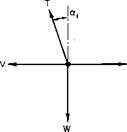
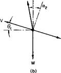
Forward Flight Rate of Climb. Consider a helicopter in a steady climbing altitude compared with the same helicopter in steady level flight, as illus­trated in Fig. 5-34.

Helicopter Performance

Fig. 5-34. Comparison between level and climbing flight: (a) level flight; (b) steady climb.

It was shown earlier that the power required by a rotor can be written approximately as

P = P,+ Pp+ TaV.

Thus the difference in the power required between the steady climb con­dition of Fig. 5-34 and the level flight condition would be

P = P2-P,= (T2cc2 – T&JV.

Assuming that all angles are small, we determine that

~ W ~ T2 ;

therefore

AP = T(a2 – ocJV.

Equilibrium of forces in the direction of flight for the climbing attitude requires that

Ta2 = D + WO,

or

Wdc = Ta2 – D,

but from the level flight condition D = Tab so that

W6C – T(ol2 — a,).

If both sides are multiplied by V, it follows that W6CV = T(a2 – a,)F

or

WVC = A P,

where Vc = rate of climb = V0C.

АР = difference in power required between climb and level flight.

For the maximum rate of climb at any V, AP should be a maximum, which means that AP should equal Pxs, the excess power, or the power available in excess of that required for level flight. Thus the maximum rate of climb in forward flight at a particular speed is

r. – (5-5»)

This equation does not apply in vertical flight, for the power required to hover cannot be compared with that required for vertical flight. It also does not apply for relatively low forward speeds for which the small angle assumptions are no longer valid.

Equation (5-59) can also be derived from energy considerations, for WVC is the rate of increase in the potential energy of the helicopter which can be

Helicopter Performance

Fig. 5-35. Climb performance.

supplied by the excess power available over that required for level flight. From (5-59) Ve obviously has its maximum value at the forward velocity that corresponds to the minimum power required for level flight.

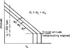
The climb performance in forward flight can now be determined by evaluating (5-59) at different gross-weight and altitude combinations. The variation of rate of climb for different gross weights appears qualitatively in Fig. 5-35.

Absolute Ceiling. The absolute ceiling for the helicopter is the altitude for a given gross weight at which the rate of climb is equal to zero. The variation of absolute ceiling with gross weight can be determined by cross-plotting the values of altitude versus W for Vc = 0.

Service Ceiling. By definition, the service ceiling is the altitude for a given gross weight at which the rate of climb is equal to 100 fpm. Again, it can be determined as a function of gross weight by cross-plotting the altitude versus W for Vc = 100 fpm.

Time-to-Climb. The time-to-climb to any altitude can be readily deter­mined once the rate of climb as a function of altitude is known. The altitude, time-to-climb, and rate of climb are related by the integral equation:

Helicopter Performance(5-60)

If Vc can be related to the altitude by a linear equation

К = Ко – Kch,

= Ao, Ко

К ‘~oe V — Kh V °ge V ’

■*VC *CO rCQ rc

Подпись: t = ТГ- log, Подпись: Ко Подпись: (5-61)

then Eq. (3-8) can be written as

where h0 is the absolute ceiling.

Observe that the time-to-climb to absolute ceiling is infinite.

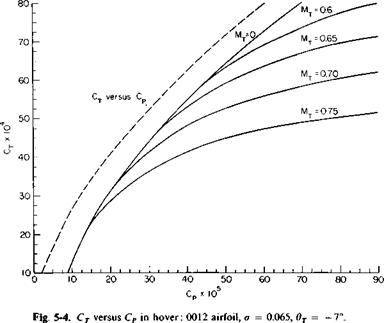
Hover Ceiling. The hover ceiling, in- and out-of-ground effect, is readily determined from the CT — CP curves and the ground effect curve, as given in Figs. 5-4 and 5-5, respectively. At each altitude, beginning with the power available, the power coefficient Cp can be calculated from

550BHP

C„ = —— 5—

p pAVP

Knowing the tip speed VT and the speed of sound at altitude, we can calculate the tip Mach number. Then, from the CT versus Cp curve, the value of CT can be determined. The value of the rotor thrust is found from

T = pAV2TCT.

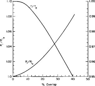
Finally, the gross weight that can be hovered at the power available is found by correcting the thrust for download according to Eq. (5-13) and for overlap according to Fig. 5-7. This would be the maximum gross weight that would be hovered out-of-ground effect at the particular altitude under consideration.

The same procedure is followed for calculating the hovering weight IGE, with the exception that the power available is increased by the reciprocal of the factor given in Fig. 5-5. The end effect on the gross weight will be nearly the same as if the gross weight to hover OGE were multiplied by the reciprocal of the factor in Fig. 5-5. This results from the fact that, within limits, the ratio of the increase in hovering gross weight to an increase in the power available is nearly constant.

The technique of linearizing the effect of design changes about a normal configuration can prove very useful, provided the aerodynamicist realizes the limitations. For example, after the geometry of a helicopter is established,

it can be advantageous to determine for the design conditions such quantities as the following:

1. Pounds of hovering weight per horsepower.

2. Horsepower per square foot of flat plate area.

3. Miles of range per square foot of flat plate area.

4. Equivalent pounds of gross weight per square foot of flat plate area.
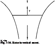
Подпись: V, +2w Fig. 5-36. Rotor in vertical ascent.

From these the approximate effects of minor design changes on the performance can be quickly estimated.

Подпись: Pi = T(VC + W) = Y
Helicopter Performance

Vertical Ascent. A rotor in vertical ascent is shown in Fig. 5-36. According to momentum theory, the power required to produce the thrust T is given by

Helicopter Performance

For a hovering rotor this becomes

Helicopter Performance

If it is assumed that the profile power of the blades remains unchanged in vertical ascent, then, for the same thrust, the difference in the power required between the vertical ascent and hover is

In terms of Pio this becomes

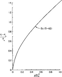
Подпись: (5-62)P, – Pi0 1 + (1 + 2T/pAV2)112 Pi0 (2 T/pAV^2

This equation is plotted in Fig. 5-37. To find the velocity Vc for a given gross weight and power available, the power required to hover is deter­mined from Fig. 5-4. The quantity P, — Pio will then be the power available minus the power required to hover. Pio can also be determined from Fig. 5-4 or estimated by increasing Eq. (5-1) 10 to 15%. The ratio of P, — Pio to Pio can now be found and the quantity 2T/AV^p found from Fig. 5-37.

The Hingeless Rotor. Interest has recently been revived in the cantilevered blade without articulation, as described, for example, in Ref. 18. Modern

Helicopter Performance

2T

Fig. 5-37. Determination of vertical rate of climb.

advances in blade materials and careful design analyses makes such a blade, frequently referred to as the “rigid rotor” because of the absence of flapping hinges, appear promising. This term is really a misnomer, however, because the blade is flexible and does in a sense flap in response to the airloads.

With the exception of the flapping relationship, the material that has been presented generally applies as well to the hingeless rotor. However, some­what analogous to hinge-offset, a moment can be imposed on the fuselage by the rotor. This appears to be one advantage of this type of rotor, namely, that its response to control movements is more rapid because of the moment transfer.

According to the reference, the cyclic stresses for the hingeless rotor are well below the allowable fatigue life of available materials. However, proponents of the articulated rotor argue that in this regard the hingeless rotor is marginal. Undoubtedly more effort is needed in this area, but it is also as certain that the hingeless rotor has been developed to a workable state and offers a definite alternative to the articulated rotor. Its proponents offer as its advantages improved stability, high maneuverability, increased allowable CG travel, and simplicity in the hub design.

Problems

1. Given a small single-place helicopter with a gross weight of 1000 lb, determine how much power is required to hover at standard sea level conditions for a disk loading of 6 psf and a tip speed of 700 fps. Use the graph of Fig. 5-4. The helicopter has an equivalent vertical flat plate area of 30 ft2.

2. At what frequency would a weight being whirled around on a string at an rpm of N oscillate if perturbed from its plane of motion?

3. A rotor has 7° of washout, a solidity of 0.07, and incorporates a 0012 airfoil. Each of its three blades weighs 1 lb/ft. It has a diameter of 30 ft and tip speed of 650 fps. What cyclic pitch is required to keep the tip path plane horizontal at a forward speed of 100 mph?

4. Construct a CT versus Cp curve for M = 0 for a rotor with a solidity of

0. 08 by correcting Fig. 5-4 for solidity.

5. The helicopter of Problem 1 has an equivalent flat plate area of 2 ft2. The CG is 5 ft below and 2 in. ahead of the rotor shaft. Calculate the power required in forward flight up to a speed at which compressibility and blade stall become significant.

6. Repeat Problem 5 with a wing attached to the helicopter. The wing has an area of 75 ft2 and an aspect ratio of 6. Repeat for different wing-lift coefficients. Assume reasonable profile drag coefficients for the wing.

Effect of Different Helicopter Configurations on the Required Power

Three principle configurations of helicopters to date have found extensive use: the single rotor with anti-torque tail rotor, the tandem configuration, and the intermeshing rotors. Each configuration has something to recom­mend it and, conversely, its adverse points; for example, the single-rotor configuration is more critical than the tandem configuration from the stand­point of loading because of the limited eg travel of the single rotor. On the other hand, the tandem-rotor configuration requires more induced power than the single-rotor because of the lower “aspect ratio” of the tandem helicopter. The relative merits of the tandem – and single-rotor helicopters are adequately covered in Refs. 14 and 15, and are not dwelt on here. Instead, problems in calculating the required power, specific to each configuration, are presented.

Single Rotor. In addition to the power required by the main rotor, the single-rotor configuration requires power for the tail rotor to overcome the torque of the main rotor. The power required by the tail rotor can be calculated in the same manner. If lT is the distance from the eg to the tail rotor, then

lTTT — Q,

where Q = main rotor torque,

TT = tail rotor thrust.

In coefficient form this becomes

r _____ ________ ZL_______

TT (lT/R)(AT/A)(VTT/VTf

where AT = tail rotor area,

Vtt = tail rotor tip speed.

Подпись: 0012 airfoil,
Effect of Different Helicopter Configurations on the Required Power

Consider the example helicopter once again. Let

From the 736 hp calculated so far CP for the main rotor is 49.5 x 10 5 Thus

CTt = 16(49.5 x 10“5) = 79.1 x 10"4,

— 6CT _ Z—Lr,

Подпись: ОCLT ~

so that

aT — 0.095.

The induced power would be approximately

C2

Cp = = 1.01 X 10"

2fi

The profile power is given approximately by C

The total power coefficient of the tail rotor is therefore CPt = 2.10 x 10 4. The corresponding tail rotor power is 20.2 hp or 2.8% of the main rotor

Effect of Different Helicopter Configurations on the Required Power

Fig. 5-25. Downwash for rotors of tandem helicopter.

power. This agrees fairly well with the percentage usually quoted for single­rotor helicopters. The tail rotor power of a single-rotor helicopter is usually of the order of 5% of the main rotor power.

Tandem-Rotor Helicopter. The tandem-rotor configuration in Fig. 5-25 does not require an antitorque tail rotor, for the main rotors rotate in opposite directions in which the torques cancel. Although this would appear to be power-saving, the tandem configuration suffers an increase in the induced power because the rear rotor operates in the downwash of the front rotor. This might be reasoned intuitively by comparison with a fixed wing; that is, the induced “drag” of a tandem helicopter for the same disk loading is higher than a single-rotor helicopter because of the lower aspect ratio of the tandem.

Although it is admittedly crude, the present method of calculating the power required by a tandem helicopter assumes that the rear rotor operates in an additional uniform downwash induced by the forward rotor. Consider Fig. 5-25.

If wf is the downwash of the forward rotor, the rear rotor acts under the influence of its own induced downwash, wa, plus the dfwf of the forward rotor. The factor df must vary between zero and 2 as the helicopter transists from hover to forward flight. For nonoverlapped rotors the interference between the rotors is negligible in hover. Actually, Ref. 16 discusses the possibility of a slight favorable interference in hover, possibly the result of an upwash induced into each rotor by the other. Obviously, from momentum or vortex considerations, the value of df cannot be any greater than 2. The

i

Effect of Different Helicopter Configurations on the Required Power

Fig. 5-26. Trailing vortex from tandem wing.

Effect of Different Helicopter Configurations on the Required Power

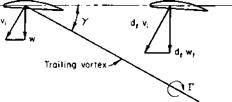
actual variation of df with forward speed is difficult to determine, for it would be expected to vary with the geometry of the helicopter—specifically with the position of the rear rotor in relation to the forward one and with the ratio of the downwash to the forward velocity, for this ratio determines the angle at which the trailing vortex system is shed from the forward rotor.

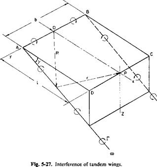
An approximate idea of how df varies, at least for nonoverlapped rotors, can be gained by applying the analogy of two wings in tandem (see Fig. 5-26).

Подпись: r = OP - R

Consider only a simple horseshoe vortex and calculate the ratio of the downwash induced at the center of the second wing to that induced at the center of the first. To do this, the Biot-Savart law can be applied to Fig. 5-27. A and В are the tips of the first wing and О is the midpoint; D, C, and P are the corresponding points on the second wing. The velocity in the Z-direction induced at P is

But

Effect of Different Helicopter Configurations on the Required Power

and

ds = dR

і dx + к tan у dx.

Effect of Different Helicopter Configurations on the Required Power

Substitution of these relationships and performance of the indicated integration results in

Effect of Different Helicopter Configurations on the Required Power

where

Подпись: P = o, Г

For

Подпись: or Effect of Different Helicopter Configurations on the Required Power Подпись: (5-52)

Hence

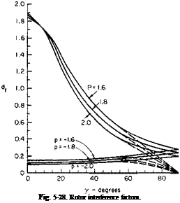
Equation (5-52) is presented graphically in Fig. 5-28. Observe that df approaches 2 as у approaches 0 and l becomes infinite. For у = п/2, df has

Подпись: Fig. 5-28. Rotor interference factors.

the value of 1/(1 + p2). The assumed model is questionable for y-values near 90°. Such values would correspond to overlapped rotors in hovering, and the results of Eqs. (5-11) and (5-12) should be used. Negative /?-values correspond to the influence of the aft rotor on the forward one. This effect is normally neglected for tandem rotors, but we can see that it may be significant for certain operating conditions.

The angle у is a function of V, w, and the trim of the helicopter. For the case in which the helicopter is trimmed level у is calculated approximately from

Подпись: 1.5wу = tan

Подпись: = tan"1.57}

2 pAfV2 where sub / refers to the forward rotor.

The ratio p is given as the distance between rotors divided by the radius. For tandem helicopters with only a small amount of overlap df varies from approximately 1.5 at 60 knots to about 1.8 at 80 knots and remains fairly constant at higher speeds.

A comparison can be made between a single rotor and a tandem helicopter

Effect of Different Helicopter Configurations on the Required Powerwith the same gross weight and disk loading by assuming that the thrust is equally divided between the two rotors of the tandem. According to simple momentum relationships, the induced power in forward flight for an isolated rotor is
T[2] [3]

P, =——–

1 2 pAV

Effect of Different Helicopter Configurations on the Required Power

For the aft rotor this becomes

Подпись: ‘total Effect of Different Helicopter Configurations on the Required Power

Thus the total P, would be

= (T/A)2T f d;

2 PV V 2

or

P = —— W + —

‘total 2 pV ~

where wd = disk loading.

Подпись: Therefore Effect of Different Helicopter Configurations on the Required Power

For a single rotor of the same gross weight and disk loading the induced power would be

of equal payload. Some of this power is also regained, in comparison with the single rotor, because of the absence of a tail rotor.

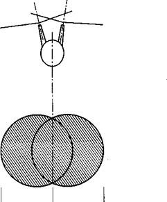
Intermeshing Rotors. The intermeshing rotor configuration is funda­mentally the same, as far as the mechanics of the fluid motion is concerned, as the single rotor. However, unlike the coaxial configuration or single rotor, the effective disk area of the intermeshing configuration is slightly noncircular because of the small lateral displacement of the two rotors shown in Fig. 5-29.

Effect of Different Helicopter Configurations on the Required Power

-«———- ь ———– *-

Fig. 5-29. Intermeshing rotor configuration.

The equations developed for the single rotor can therefore be applied to the configuration with intermeshing rotors. For calculation of the induced power the shaded area in Fig. 5-29 should be used for the disk area. For calculation of the rotor solidity the total solidity of both rotors should be used. The induced power in forward flight should be based on the combined span b.

Retreating Blade Stall Limitations

The preceding section showed that retreating blade stall results in a severe increase in the required power. An equally important effect of the onset of retreating blade stall is the accompanying increase in the vibration level and blade stresses. It is therefore important in the design of a helicopter that the rotor be selected to avoid the occurrence of retreating blade stall throughout the intended operating regime.

It has been found that the inception of retreating blade stall can be pre­dicted relatively simply by assuming that the loading distribution is similar for all rotors. It follows then that the section lift coefficient near the tip of
the retreating blade is proportional to the blade loading and the resultant tip velocity.

c kWb

,m“ (p/2)(cdR – V)2’

where к = constant of proportionality, wb = blade loading.

With some algebraic manipulation this can be written as

The constant of proportionality varies with the blade twist, for varying the twist shifts the loading in – or outboard on the blade. From a series of power-required calculations, as previously described, the constant к is given

by

к = 3.17 – 2.79T,

where вт = total twist in radians, usually negative.

Consider the example helicopter just studied in terms of Eq. (5-51):

— 6Cr CL = —T – = 0.555, a

C, = 1.25,

(max 7

к = 3.5.

Thus

Подпись: - = 0.517,С, к

C, 3

•max

Подпись: so that

detail = 1 — 0-72
= 0.28.

Indeed, it was found that the rotor suffered a power loss at p = 0.31, which is in excess of this value.

Blade Element Method for Calculating the Power Required in Forward Flight Including Compressibility and Blade Stall

In order to develop a blade element method for calculating the power required in forward flight, it is necessary to consider the dynamics of the rotor and the trim of the helicopter.

Rotor flapping and blade pitch were discussed briefly in the beginning of this chapter.

The blade pitch angle в at any station x shown in Fig. 5-3 is usually given for a uniformly twisted blade as

6 = 0o + 0Tx + cos ф + 02 sin ф + Kpfl, (5-28)

where 90 = collective pitch,

6T = total twist, в і = lateral cyclic, в2 = longitudinal cyclic,

Kp = дв/dp = S3 effect.

Although the cos ф term is a maximum at ф = 0, 01 is the lateral cyclic pitch, for it gives rise to an aerodynamic flapping which lags it by 90° and is termed lateral flapping. A similar statement is true of 62; Kfi, the 63 effect, is the result of cocking the flapping axis of the blade so that its pitch is varied as the blade flaps.

The forward motion of the helicopter combined with cyclic control pro­duces blade flapping defined by

P = Po — c°s ^ sin 0- — a2 cos 2ф — ■■■ (5-29)

where p0 = coning angle (independent of ф),

= longitudinal flapping, bi = lateral flapping, a2> b2, a3,… = higher harmonics.

For purposes of calculating the power required only first harmonic flapping is considered. It should be remembered that both the pitch and flapping angles are with respect to the disk plane, the plane normal to the rotor shaft axis. Observe that a positive value of results in a nose-up position of the tip-path plane with respect to the disk plane.

There are two dimensionless ratios ascribed to a given state of rotor operation: the inflow ratio Я and the tip speed ratio ц; ц is the ratio of the rotor translational velocity to the velocity at the tip due to rotation.

Подпись: (5-30)V V

o)R VT

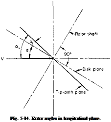
Подпись: Fig. 5-14. Rotor angles in longitudinal plane.

The inflow ratio X is similar to the advance ratio X used for propellers but should not be confused with it. The inflow ratio X is the ratio of the net velocity up through the disk plane to the tip speed. In order to calculate X,

it is necessary to define one other angle, namely, a, the angle of attack of the rotor disk plane. This angle a is the angle between the incoming free-stream velocity and the rotor disk plane defined positively if the disk plane is nose-up; a and a1 are shown positively in Fig. 5-14.

If w is the downwash velocity at the rotor, then from Fig. 5-14 it can be seen that if all angles are assumed small

Подпись: (5-31). Va — w

a>R

Blade Element Method for Calculating the Power Required in Forward Flight Including Compressibility and Blade Stall Подпись: V(a + at) — w a>R

Later we use an inflow ratio Av which is simply the ratio of the net velocity up through the tip-path plane to the tip speed. This is given by

(oR + 0l coR

or

Av = A + axfi. (5-32)

The angles в0, 0T, 9X, 02, fi0, au bx, a and the ratios fi and A, together with the thrust coefficient CT, are all interrelated. These relationships have been the subject of many investigations, a few of which are given in the references. The reader is referred in particular to Wheatley’s [10] original work.

Rather than discuss these investigations in detail, we present here in a simplified, easy-to-use manner, the results for a uniformly twisted, non – tapered blade. The thrust coefficient CT can be obtained simply as

ct = y [ЯГі + {во + K^o)T2 + °тТз + (02 “ *А)Г4].

But

w _CT

Vt~ V

Therefore

ct = {l+aj^a/4ll) 1>г1 + (fl. + kA)J2 + 0TT3 + (02 – (5-33)

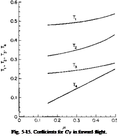
where Tu T2, T3, and T4 are functions of ц and B, the effective dimensionless radius used in Chapter 4.

T, = ЦВ2 + in2), T3 = $B2(B2 + fi2),

T2 = ВЪ + fi2B, T4 = Ыв2 + in2).

a = section lift curve slope in Ct per radian, a = rotor solidity.

The above is obtained from an average thrust defined as that giving the same impulse per revolution as the time-varying thrust. In one revolution the differential thrust provides an impulse given by

or, since со = diji/dt,

1 Г2я dl = – dTdi/i; "Jo

‘2я _ 1_ f2* " / "Jo

Подпись: dT Подпись: йГГ#

an average df is obtained from

or

Подпись: р2я– 1 f2

dT = — dT <іф.

2rtJ0

The coning angle can be obtained from

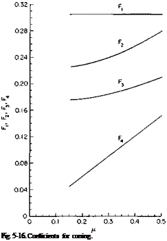
Po = 7f^F1 + (в0 + Kffi0)F2 + 9TFз + (02 – V,)F*] – r (5-34) where

F2 = jB2(B2 + /І2), F4 = i/cB3,

cpaR*

Подпись: Fi =

Blade Element Method for Calculating the Power Required in Forward Flight Including Compressibility and Blade Stall

F3 = B3(jB2 + У2),

The lateral flapping bx is given by

b = До-®и — (®i ~ (5-36)

Blade Element Method for Calculating the Power Required in Forward Flight Including Compressibility and Blade Stall Подпись: 4цВ З (В2 + №)’

where

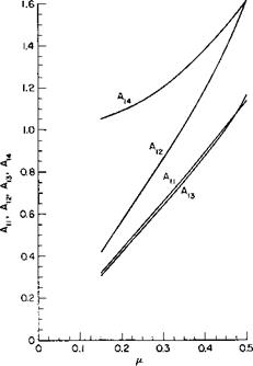
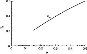
The coefficients Tu T2, Т3, Т4, Fu F2, F3, F4, А1Ь A12, A13, Аы, and Bu are given in Figs. 5-15, 5-16, 5-17, and 5-18 as a function of ц for an assumed В value of 0.97.

Подпись: Fig. 5-15. Coefficients for CT in forward flight.

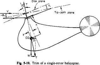
In addition to these relationships, it is necessary to consider the trim of the helicopter. A single-rotor helicopter is shown schematically in Fig. 5-19.

From this figure it can be seen that unless there is a trimming horizontal stabilizer or hinge-offset (to be discussed later) the thrust vector must pass through the CG and be equal and opposite to the resultant of the weight and the drag. (This assumes in the simplified case that the drag acts at the CG.) For small angles the result is obtained that

ZFC = 0 T аг W,

£FX = 0 .’. T( — a — Uj) = D,

or

<5-3T>

It can also be seen that if the CG is a ^-distance ahead of the rotor shaft and h below it then

(5-38)

Blade Element Method for Calculating the Power Required in Forward Flight Including Compressibility and Blade Stall Подпись: D w' Подпись: (5-39)

Therefore

Подпись: Fig. 5-16. Coefficients for coning.

Although greatly simplified, the foregoing illustrates the procedure of calculating the longitudinal trim of a helicopter. In a tandem helicopter the equations must be modified to include the forces and moments due to both rotors. Some single rotor helicopters employ a significant amount of hinge offset to introduce a pitching moment proportional to the flapping. That such a moment can exist, consider a two-bladed rotor at the instant the blades are fore and aft, as shown in Fig. 5-20.

If F is the resultant force on any blade, then it can be seen from the figure that the instantaneous moment produced by the blade is

M = 2 FeRau

where e is the hinge-offset dimensionless distance from center to flapping hinge.

Blade Element Method for Calculating the Power Required in Forward Flight Including Compressibility and Blade Stall

Fig. 5-17. Coefficients for first harmonic longitudinal flapping.

Blade Element Method for Calculating the Power Required in Forward Flight Including Compressibility and Blade Stall

Fig. 5-18. Coefficients for first harmonic lateral flapping.

The average moment about the ф = тг/2 axis, as the blade travels around the azimuth, would be half this value for a two-bladed rotor.

Forces Acting on a Blade Element. The simplified theory of forward flight expressed by Eq. (5-27) was derived on the assumption that the drag

Blade Element Method for Calculating the Power Required in Forward Flight Including Compressibility and Blade Stall

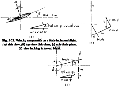
coefficient is constant, independent of r and ф. To improve on that as­sumption it is necessary to examine the various velocity components that influence a blade section. Consider Fig. 5-21 and refer to the side view. The disk plane, or plane perpendicular to the axis of rotation, is at an angle of attack a. Hence, in relation to the disk plane, a component Fa is going up through the disk. From Fig. 5-216 the velocity normal to the blade is cor,

Blade Element Method for Calculating the Power Required in Forward Flight Including Compressibility and Blade Stall

Fig. 5-20. Rotor moment due to hinge-offset.

plus a component of V, V sin ф. A component V cos ф is directed out along the blade. Now, looking at the plane containing the blade and the axis of rotation, we see that the component V cos ф directed out along the blade has a component down relative to the blade equal to Vfi cos ф. If the blade is flapping up at an angular velocity of /?, then, relative to the blade suction at a radius of r, a velocity is coming down equal to rfi. Also shown in this view is the downwash w which results from the thrust and the upward velocity Fa obtained from the side view.

Blade Element Method for Calculating the Power Required in Forward Flight Including Compressibility and Blade Stall

Finally, looking in along the blade at a section of it, we find that the total vertical downward velocity relative to the section is VP cos ф + w + rP — Fa. The component in the disk plane normal to the blade radius is

cor + V sin ф. Hence, if в is the pitch angle relative to the disk plane, the angle of attack of the section is

Подпись: <x(r, ф) = в -VP COS Ф + W + rP — Vol
cor + V sin ф

This can be made dimensionless by dividing by coR and remembering that

1 = [10L — w/VT.

Подпись: a(r, ф) = в -цР cos ф + x(P/co) — X X + Ц sin ф ’

but 0 and p were given previously by Eqs. (5-28) and (5-29). Therefore a = 0O + 9Tx + 0t cos ф + Q2 sin ф + K0O — cos ф)

цРо cos ф — (pat/2) – I – xat sin ф — X
X + Ц sin ф

In (5-40) ftjias been taken equal to zero from lateral trim conditions and a cos 2ф term has been dropped as a higher harmonic. The differential lift dL is given by

dL = pV2ecC, dr,

where

К — фс + A* sin Ф)2 +

The differential drag is

Подпись: (n №1 • , Wo —Y + x°l sm ^ Blade Element Method for Calculating the Power Required in Forward Flight Including Compressibility and Blade Stall

Ci = a0a,

dD = jpV2cCd dr,

where Cd = C/C,).

In terms of the differential lift, drag, and the angle ф, the average thrust and torque is

T = ~ J ~ VeC(C, cos ф – Cd sin ф) dr dф,

Q = J I Vecr(C, sin ф + Cd cos ф) dr сіф.

Dimensionless thrust and power coefficients defined according to Eqs. (5-2) and (5-3) can be determined from

CT = J j" (cicos Ф ~ Cd sin ф) dx thft, (5-41)

CP = — f2" f1 o(— x(C, sin ф + Cd cos ф) dx (іф. (5-42)

4л Jo Jxk VTJ

To do a more precise calculation, we would integrate Eqs. (5-41) and (5-42) numerically on a digital computer. The desired CT, given the weight ind tip speed, would be known. Also, by knowing the helicopter geometry, drag, and forward speed we could readily determine w, a, au and bv We would then calculate an approximate value of 60 from Eq. (5-33) and follow it by P0 from (5-34) and from (5-36). Equation (5-41) would then be integrated for CT. If the integrated value of CT did not equal the desired value, 0„ would be adjusted accordingly and the integration repeated.

In performing the numerical integration we would examine the section C, and Mach number at each ф and x; Cd would be chosen accordingly as a

function of C, and M. Of course, C, would be limited to a value of C,____

which would also be a function of M.

The assumption of a uniform downwash, w, over the disk is known to be in need of improvement. Although considerable effort has been expended by many on this particular question, there is still no accepted alternative. Reference 11, for example, multiplies w from Eq. (5-22) by the factor 1/(1 — 3^2/2) as a correction for the lateral dissymmetry in the Г-distribu – tion. However, Ref. 17 shows that this is incorrect and that the correction factor arose as the result of neglecting certain vorticity components in the derivation.

With the increasing availability of computers, the trend is toward precise stepwise numerical calculations which account in detail for the influence of the trailing vortex systems from all the blades. Reference 19 is an example of this approach.

Correction for Stall. Reference 11 presents an expression, CPs, for the addition to the power coefficient given by Eq. (5-25). This increment, CPt, is required to account for the increase in rotor torque caused by retreating blade stall. It is assumed that at the stall a jump of 0.08 occurs in the value of the section drag coefficient and that the rotor area within which blade stall exists is a pie-shaped segment of minimum dimensionless radius Xs symmetric about ф = Ъп/2.

Under these assumptions CPi becomes

Подпись: (5-43)cP. = – d2(i – Wi – xl

The dimensionless radius Xs, outboard of which blade stall is present, can be found by equating the section angle of attack of a general rotor section at ф = 270° to the angle of attack corresponding to C)ni>x. The angle of attack of a rotor section is given by Eq. (5-40).

Подпись: This can be solved for Xs as

For the retreating blade ф = 270°, the equation immediately before Eq. (5-40) equated to 0:max becomes

Blade Element Method for Calculating the Power Required in Forward Flight Including Compressibility and Blade Stall(5-45)

where В = ax – fidT – Г,
С = цГ -(- A,

It is necessary to modify the correction given by (5-43) for reasons that are now given. Reference 11 assumes a pie-shaped segment of the azimuth travel during which the blade is stalled (see Fig. 5-22).

Blade Element Method for Calculating the Power Required in Forward Flight Including Compressibility and Blade Stall

v

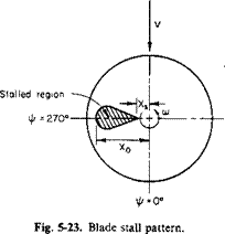
The correction CPs is a function of the dimensionless radius Xs, outboard of which the blade is stalled. This picture is satisfactory for the usual rotor. However, depending on the inflow ratio and blade twist, it is possible for the blade section angles of attack to be higher inboard than at the tip, which will result in the stall pattern shown in Fig. 5-23.

For the same value of Xs the stall pattern of Fig. 5-23 will obviously require less power than that assumed by Eq. (5-43).

The distance is the other root of Eq. (5-44):

Подпись:-В – УВ2 – 4втС

Blade Element Method for Calculating the Power Required in Forward Flight Including Compressibility and Blade Stall

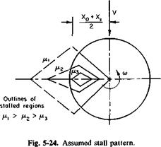
To correct Eq. (5-43) for this possible inboard stalling we assume that the stalled region is diamond-shaped. This is shown in Fig. 5-24 for varying values of p.

As. Xq approaches Xs, the correction for stall CPs must vanish. Similarly, as the average between X0 and Xs approaches unity, CPt must approach the value given by Eq. (5-43). This average, according to Eqs. (5-47) and (5-48) is

x±±xI= _B_

2 2вт

Thus a factor, ks, is defined, which multiplies Eq. (5-43) such that ks = 1 for — B/26T > 1 and decreases linearly to zero as — B/26T approaches Xs. Therefore

where

Compressibility Correction. A theoretical investigation of the effects of compressibility on the performance of a helicopter rotor in various flight conditions is given in Ref. 12. The results of this study show that regardless of p (for a p at least as low as 0.2 to as high as 0.5) the compressibility losses can be expressed as an increment in CP/o as a function of the amount by which the drag-divergence Mach number is exceeded at the tip of the advancing blade. It is also stated that experimental data show the drag
divergence Mach number to be approximately 0.06 higher than two – dimensional tests would indicate.

Thus from this report the following addition to the power coefficient can be formulated:

Подпись: (5-49)CPo = ct[0.012A Md + 0.100(AMd)3],

where AMd = Mj( 1 + ц) — Mcrit — 0.06,

MT = coR/a0 — tip Mach number,

Mcrit = critical Mach number of advancing blade аіф = 90°. The angle of attack аіф = 90° can be obtained from Eq. (5-40).

Blade Element Method for Calculating the Power Required in Forward Flight Including Compressibility and Blade Stall(5-50)

Although Eq. (5-49) is relatively simple, it gives results that are in apparent agreement with experimental data. Mcrit can be obtained from theoretical calculations of airfoil characteristics in Ref. 13.

Application of Equations

The previously developed equations are lengthy to apply to the calcula­tion of the power required in forward flight. Fortunately, in these days of high-speed automatic computers this is not a serious objection. Most helicopter manufacturers have trim analyses programmed on digital com­puters so that for a given operating condition values of A, au fi0, 0o, and 62 can be readily obtained.

For purposes of preliminary analysis, however, an approximate trim analysis can be made. The application of the foregoing equations is perhaps best explained by the use of a specific example. Consider a fictitious single­rotor helicopter with the following characteristics :

Gross weight = 7000 lb.

Rotor diameter = 40 ft.

(oR = 650 fps.

a = 0.06.

/ = 16 sq ft = equivalent flat plate area. No hinge offset.

6T — —0.122 radians = —7°.

K, = 0.

t = 0.00228.

= 5.5.

Center of gravity on rotor disk axis.

Подпись: 1Подпись: 0.0085, dl = 0, 0.008, a = 5.73, 12.5° = 0.218 radians, 0.71 - 2.3a (radians). Rotor airfoil section = 0012 s

®max

In a more exact calculation, of course, account will have to be taken of the variation of amax with tip Mach number. We shall now calculate the power required by the helicopter operating at a speed of 120 knots at sea level. Initially, the power required by the antitorque tail rotor is not con­sidered. However, it is covered later in more detail.

The power is calculated according to the simplified method. From Eq. (5-22)

T 7000

W z= ——————————- — ______________________________________________

2pVnR2 2(0.002378)(202)(1255)

= 5.8 fps.

From (5-23)

Pt = Tw = (7000X5.8) = 40,500 ft-lb/sec = 74 hp.

The parasite power can be calculated as

– DV – yv>f – ft002378f02)i|l6) – 156,000 ft-lb/sec

= 283 hp.

The profile power is obtained from

P„ = P 0(1 + 4p2).

The profile power P0 for /i = 0 can be determined from Fig. 5-4 and suit­able corrections or calculated approximately as

aS° J-9 X CT

Подпись: r"o= —^—г – d2—–

Using the above, we obtain

T 7000

pAV2 ~ (0.002378)(1255X650)2

= 55.5 x 10“4.

Therefore

(0.06X0.0085) 9(0.008)(55.5 x 10“4)2

8 + 2 (0.06)

= 6.55 x 10⁻⁵.

Blade Element Method for Calculating the Power Required in Forward Flight Including Compressibility and Blade Stall Blade Element Method for Calculating the Power Required in Forward Flight Including Compressibility and Blade Stall Подпись: + (8 - 7) x 10“5 Подпись: 0.065 ,0.06
Blade Element Method for Calculating the Power Required in Forward Flight Including Compressibility and Blade Stall

From Eq. (5-10) and Fig. 5-4

Hence

P0 = pAVCPpi> = 0.002378(1255)6503(6.55 x 10’5)

= 53,600 ft-lb/sec = 97.3 hp.

Therefore, because p = V/V, = 0.31,

P„ = 97.3 [ 1 + 4(0.31)2]

= 135 hp.

Thus the total main rotor power required would be

p = 74 + 283 + 135 = 492 hp.

To determine the actual engine power required, it would, of course, be necessary to include the tail rotor power, the accessory power, the cooling power, and the transmission losses.

Consider now the additions to the power for retreating blade stall and compressibility effects.

First a check should be made to determine whether the blade is stalled or whether the critical Mach number is exceeded.

From Eqs. (5-50) and (5-44) it can be seen that this requires the deter­mination of в0 and в2. It is assumed that there is no lateral flapping so that b2 = 0. Now for p = 0.31

Tx = 0.495,

T3 = 0.245,

T2 = 0.350,

II

p

ел

p

Ац = 0.680,

A13 = 0.660,

A12 = 0.890,

A1A = 1.21,

A1S = 0.230.

Equation (5-33), therefore, becomes

2 c

— = Я71 + Є0Т2 + ЄтТ3 + 02T4,

0.0323 = -0.0223 + O.35O0o – 0.0300 + 0.1502, or

O.35O0o + 0.1502 = 0.0846.

Equation (5-35) becomes

0 = лАц + 00^12 + ^Г^ІЗ + 02^14>

0 = -0.0306 + 0.8900 – 0.0805 + 1.2102, or

O.890Q + 1.210J = 0.111.

These equations can be solved to give

0O = 0.2957 radians = 17°,

02 = -0.1255 radians = -7.17°.

The terms for Eq. (5-45) are therefore

Г = -0.203,

В = 0.241,

С = -0.108.

Thus

xs = 0.712,

whereas

—0 ^ Xs = 0.985 and ks = 0.95.

The blade is stalled, with the additional required power being given by Eq. (5-43):

CPs = 14.5 x 10“5.

The section angle of attack at ij/ = 90° is obtained from Eq. (5-50) as

л

a90 = 00 + 02 + 0y H————— ^———

1 + Ц

= 0.0136 radians = 0.777 degrees.

Therefore Mcrit = 0.71 — 0.031 = 0.679. The tip Mach number is

Подпись: 0.765,650 + 202
1116

and

AMd = 0.765 – 0.679 – 0.06 = 0.026.

From Eq. (5-49) the additional power required to overcome compressibility losses is

CPc = 1.88 x 10~5.

Thus the additional power required to overcome blade stall and com­pressibility amounts to

Ahp stall = 216,

Ahp compressibility = 28.

The total horsepower required with the percentage breakdown is given in Table 5-1.

Table 5-1

Power Required Including Blade Stall and Compressibility

Hp

% of Total

Parasite

283

38.4

Induced

74

10.0

Profile

135

18.3

Blade stall

216

29.3

Compressibility

28

4.0

Total

736

100

Simplified Theory of Forward-Flight

Consider the induced power required for sustaining lift with an elliptic wing.

Pi = Div = La, V

= Lw,

where P, = induced power,

D, = induced drag,

a, = induced angle of attack,

L = lift,

w — velocity induced at the wing.

These results show that the induced power is equal to the product of the

Simplified Theory of Forward-Flight

lift and the induced velocity. The induced velocity for an elliptic wing was derived in Chapter 3 and is given by

Because the aspect ratio is AR = b2/S, the above equation can be written as

L = (2w),

where b equals the wing span.

Simplified Theory of Forward-Flight

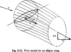
In words this equation states that the lift of an elliptic wing is equal to the product of twice the induced velocity and the mass rate of flow passing

through a circle with a diameter equal to the span of the wing and lying in a plane normal to V. This is illustrated in Fig. 5-12.

This same concept is now applied to a lifting rotor in forward flight; that is, the thrust and downwash at the rotor are related by assuming that

T = pVnR22w. (5-22)

The induced power then becomes

Подпись: (5-23)P, = Tw T2

~ IpVnR2

If, in addition, the thrust vector is tilted forward through a small angle a,

useful work is being performed at the rate of TaV. Thus, in general, the ideal power required by a rotor in forward flight is

Подпись: (5-24)P = TaV + Pj = T(aV + w).

From Fig. 5-12 it can be seen that (aV + w) is simply the resultant velocity normal to the rotor disk plane. Thus, in words, it can be stated that the ideal power is given by the product of the thrust and the velocity normal to the disk.

In addition to this ideal power, the rotor requires a certain amount of power to overcome the profile drag of the rotor blade sections. This power, which is covered in some detail later, is referred to as profile power.

For steady forward flight the forward horizontal component of thrust Та must equal the parasite drag of the helicopter. Thus TaV is termed the parasite power and is equal to

iV = DV.

The total power required by a helicopter rotor in forward flight can now be seen to be composed of three parts.

Подпись:P = Pi + Pp&T + Pp = (induced) + (parasite) + (profile)

Equation (5-22), as proposed by Glauert, is written more specifically as

Подпись: (5-26)T = pV’nR22w;

V is the vector sum of v and w as shown in Fig. 5-12.

Simplified Theory of Forward-Flight

It is difficult to draw an analogy between this equation and the elliptic wing, but it has the advantage of agreeing with the hovering rotor in one limit as V -*• 0 and the elliptic wing at the other extreme as w/V -» 0. From this equation w can be obtained as

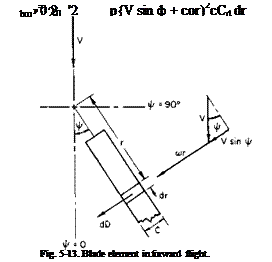
Profile Power. Consider the drag of a blade element in Fig. 5-13. The differential drag on this element is

dD = jp(V sin ф + a>r)2cCd dr.

Simplified Theory of Forward-Flight

In one complete revolution the work performed by dD is

Подпись: P Подпись: r dD cbj/,
Simplified Theory of Forward-Flight

The average power is equal to the work divided by the time required for one revolution. Hence the average power for b blades is

Simplified Theory of Forward-Flight

or for the profile power

For a constant value of c and an assumed constant value of Cd, this becomes

Подпись: b{(oR)3R2p(c/R)Cd An Подпись: '2 n 04

x(p sin ф + x)2 dx dф о

= Po( 1 + p2)

where P0 = profile power required in hover (p = 0),

= V/coR.

(*R

Подпись: A P„ Simplified Theory of Forward-Flight

In adddition to overcoming the torque produced by the profile drag of the blades, more parasite power is required because of the blade profile drag:

Because it has the same form as profile power, this increment is usually included there, and Pp becomes

Pp = P0( 1 + іц2). (5-27)

The constant 3 in front of ц2 has become somewhat of a “fudge factor” and varies from manufacturer to manufacturer. Because of the aerodynamic uncleanliness of the root end of the rotor blades, this constant is usually increased in practice to 4 or more.

By expressing Pp as a function of ц and P0, we lessen the objection of assuming a constant Cd value, for P0 can be determined accurately without the use of such an assumption.

Forward Flight

The prediction of rotor characteristics in forward flight presents many problems. The unbalance in the velocity at corresponding locations on the advancing and retreating blades, as discussed earlier, gives rise to aero­dynamic flapping which effects a change in the angle of attack of a blade section as it transverses the azimuth. The cyclic pitch control also varies the blade pitch angle around the azimuth. Compressibility and stall effects vary appreciably around the azimuth. The bound circulation of the blade changes periodically, leaving a varying trailing vortex sheet in its wake. The heli­copter rotor blade offers a crowning example of unsteady aerodynamic phenomena.

In spite of these difficulties, the helicopter aerodynamicist is able to pre­dict with reasonable satisfaction the power required by a helicopter in forward flight. There is a limited range of low speeds in which the calcula­tions are doubtful because of the induced power, and at high forward speeds the calculations are questionable because of retreating blade stall and com­pressibility effects. A method, presented later, has been found to give results of compressibility and retreating blade stall that are in agreement with test data.

Before investigating in detail the aerodynamic forces on a rotor blade in forward flight we can gain considerable insight into the power required in a study of its separate sources.

Autorotation

Autorotation Подпись: Torque - producing force

Helicopters are equipped with overriding clutches so that, in the event of power failure, the rotor will not be restrained by the engine but will be free to rotate. Immediately after a power failure the pilot must “dump” his collective pitch within two to three seconds. With decreased collective pitch, the rotor will autorotate as the helicopter begins to descend; that is, the aerodynamic forces on the rotor will cause it to rotate even though no mechanical torque is present. That such an aerodynamic torque can exist can be seen in Fig. 5-10. In descending, the resultant velocity is directed

і

Fig. 5-10. Blade section in descent.

upward by the combination of linear velocity from rotation (cor) and descent velocity (VD). The lift vector is therefore tilted forward with respect to the axis of rotation. If the angle tan-1 (VD/a>r) is too large, the section will stall and destroy the lift, hence the accelerating force; if this same angle is too small, the lift vector will not be tilted far enough forward to overcome the drag of the section and the force on the section will be a decelerating one. Thus in autorotation, in which the net aerodynamic torque on the rotor must be zero, only the middle portion of the blade produces an accelerating force. The inner portion is stalled, whereas the outer region near the tip produces a decelerating force. Figure 5-10 also shows why it is important to decrease collective pitch, for failure to do this will cause the blade to stall and the rpm to decay rapidly.

The successful emergence from a power failure is only secondarily de­pendent on the sink rate. It is dependent primarily on the ratio of the rotational energy stored in the rotating mass of the rotor to the translational energy of the helicopter. Ratios of rotor rotational energy to helicopter translational energy of the order of 3 or 4 have given satisfactory flare characteristics in practice.

The transition of a helicopter from hovering to unpowered vertical ascent has been the subject of many investigations. Most analyses are based on a numerical solution of the equations of motion of the rotor and the helicopter. Reference 9 presents a simplified analysis of the motion during transition which is valid for the first few seconds before pilot action or before too great a build-up in VD.

Autorotation

If T is the thrust produced by the rotor at any instant of time t, the acceleration of the aircraft in the downward vertical direction is given by

where W = helicopter weight.

The equation of motion of the rotor is

Ja> = Qs~ Qa,

where J = polar moment of inertia of the rotor, со = angular velocity,

Qs = shaft torque tending to increase,

Qa = aerodynamic torque tending to decrease со.

Autorotation

For complete power failure Qs = 0. If it is assumed that the collective pitch of the rotor will remain unchanged and the vertical descent velocity is small in comparison to the rotor tip speed, the dimensionless thrust and power (or torque) coefficients will remain constant. Assuming that CT and CQ are constant, we obtain

where

Подпись: QQ pVfaR3’

QS0 = Qs for t < 0.

do da)’ dt’ da) o’QS0

dt dt’ dt do’ J

Подпись: so that

o’ = —ft)’2.

The solution to this equation is

Подпись: (5-19) of motion of the helicopter / 1 VI Подпись:Подпись: (5-20)

Подпись: Thus
Autorotation
Подпись: Let
Подпись: Then

o’ = (1 + I’)"1-

Substitution of Eq. (5-19) into the equation produces

This equation can be integrated to yield

1 + t’

I = 1 -£ + ^log(l + 0, (5-21)

where

V = gt,

h = igt2.

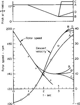
The figures in Ref. 9 are reproduced here as Figs. 5-1 la and 5-1 lb. Observe that the approximate equations (5-19), (5-20), and (5-21) agree well with the more refined calculations for the first few seconds.

If the log term in Eq. (5-21) is expanded for small values of t’, this equation becomes

Autorotation

Fig. 5-lla. Comparison between approximate and refined calculations for vertical descent ‘exact’ theory; O. x, Eqs. (5-19), (5-20).


10° –


-L.

о о 0) ~ ~ a.


Autorotation

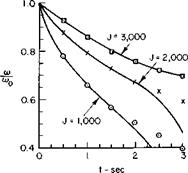
Fig. 5-116. Effect of rotor inertia on decay of rotor speed; ‘exact’ theory; □. x, 0, Eq. (5-19).


which demonstrates the importance of having a high ratio of rotor angular momentum to rotor shaft torque. The higher the ratio, the smaller the amount by which the helicopter would fall in a given time.

Vertical Descent

The space age has discounted the old axiom that what goes up must come down. However, the statement still applies to the helicopter. Hence this section investigates the rotor aerodynamics of operating in a vertical descent with zero or partial power.

The operating state of a rotor, normal to its disk plane, has been historically characterized by the direction and magnitude of its thrust vector

Vertical Descent

(c) (d)

Vertical Descent

(e)

Fig. 5-8. Working states of an airscreen: (a) normal; (b) zero-thrust; (c) windmill; (d) turbulent

windmill; (e) vortex ring.

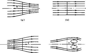
and the resulting flow through the disk. The various states of flow are best visualized by starting with the rotor in the normal state of operation and then decreasing the thrust to zero, reversing its direction and then increasing its magnitude. In this manner the rotor passes consecutively through the normal, zero-thrust, windmill, turbulent windmill, and vortex-ring states. These states are illustrated in Fig. 5-8.

The analysis of a rotor in the turbulent windmill and vortex-ring states is difficult because of the irregularity of the nature of the flow through the disk and in the wake. Glauert [8] proposes the use of two parameters

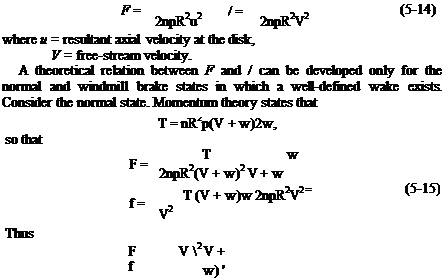
Vertical Descent

throughout the operating states of the rotor. These parameters,/and F, are defined by


Vertical Descent

Vertical Descent

Solving for w from (5-15) we obtain finally

у = (1 – Л2. (5-16)

In the windmill brake area w subtracts from the free-stream velocity

T = nR2p(V – w)2w,

so that

j = (1 + F)2- (5-17)

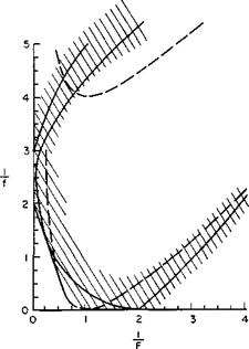
In the other operating states the relation between / and F must be deter­mined experimentally. Several difficulties are encountered in doing this. The main problem is that the velocity u, as used in Eq. (5-14), is an “average” velocity through the disk, whereas, in the vortex-ring state the flow varies radically from a uniform distribution. Considerable disagreement exists among various investigators about the relation between/and F, particularly for values of 1 /F less than 2. Figure 5-9 presents the theoretical variation of 1 // versus l/F for the windmill brake and normal working states together with a band of experimental data which has been obtained to date.

In practice, it is sufficiently accurate to calculate the vertical descent velocity by simple momentum theory. The minimum sink rate of a typical helicopter is then approximately 60% of the vertical descent velocity and occurs at approximately the speed for best climb.

The limiting vertical descent velocity in autorotation can be found from simple momentum theory.

T = pA(VB — w)2w.

The limiting vertical descent velocity VD can be obtained from considera­tions of the transfer of kinetic energy from the flow to the rotor. However, it is most readily obtained by expressing VD as a function of w and finding the value

As stated previously, the minimum sink rate in autorotation occurs in forward flight and is approximately 60% of the value given by Eq. (5-18).

Special Problems in Hover

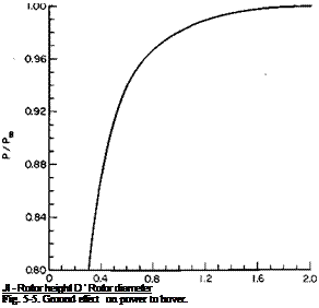
Ground Effect. The effect of ground proximity on the hovering rotor is to reduce the induced power required to deliver a given thrust. Essentially, the ground plane creates an image rotor that induces an upward velocity, which in turn reduces the induced angle of attack so that the lift vector of each section is tilted more nearly vertical. A theoretical analysis of ground effect can be found in Ref. 6.

Although the ground effect is on the induced power only, it is common practice to account for it with a correction factor to the total power. This factor, which is the ratio of power required to hover IGE (in-ground effect) to that required to hover OGE, is a function of the ratio of the height of the rotor above the ground to the rotor diameter. It would be expected to hold only as long as the induced power required to hover is approximately the same proportion of the total power in the test data from which the factor was obtained; for example, the power required to hover IGE divided by the power required for OGE should be less for the more heavily loaded rotors of VTOL aircraft than for a helicopter rotor. Figure 5-5 is a graph which shows the ratio of power required to hover IGE to that required to hover OGE for the average helicopter. This curve was obtained as the best fit to considerable amounts of test data on both single and tandem rotor helicopters.

Rotor Interference. A problem peculiar to the multirotor helicopter is that of rotor interference. Reference 7 presents a theoretical treatment of the effect of rotor overlap on the induced power which compares favorably with test data. The following is an approach to the problem which agrees closely with results of Ref. 7.

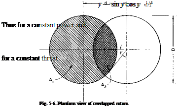
Consider two overlapped rotors as shown in Fig. 5-6.

Let T equal the thrust of both rotors; ut equals an “average’ induced velocity.

If the profile power Pp is assumed to be independent of the overlap for a given thrust, then, for a constant induced power, the thrust must vary inversely as the induced velocity, for P, = Tvt. Thus

l = s,

T0 v

Подпись: Jl - Rotor height D ’ Rotor diameter Fig. 5-5. Ground effect on power to hover.

where a sub 0 refers to zero overlap.

Now

1/3

Similarly, for a constant thrust the ratio of the induced powers with and without overlap is

(РЛ _ (M112.

Pio/constant thrust AJ

If the overlap is defined as 1 — d/D, the angle shown on Fig. 5-6 is given

by

у = cos-1 (1 — overlap) and from the geometry of the figure

A у — sin у cos у

Special Problems in Hover Special Problems in Hover

A0 %

These relations are presented graphically in Fig. 5-7 as a function of the overlap.

Fuselage Download. The thrust that a rotor must develop in hover is actually greater than the gross weight of the helicopter, because the down – wash from the rotor (or rotors) produces a vertical drag on the fuselage in
the downward direction. This additional download can be calculated approximately as the product of the disk loading (dynamic pressure in ultimate wake) and an equivalent flat plate area,/„, of the fuselage planform area in the rotor slipstream:

T

download = — /„.

il

Thus

T=w + jL (5-13)

or

T w

~ 1 – ША)

From this equation it can be seen that the gross weight of the helicopter should be increased by the factor [1 – (fJA) ~1 in order to calculate the

Special Problems in Hover

Fig. 5-7. Effect of overlap.

power required by the rotors in hover. This factor increases the thrust by approximately 1% for single-rotor helicopters to 3% for multirotor con­figurations, numbers which can vary considerably, however, depending on the specific distribution and shape of fuselage area beneath the rotor.

Application of Vortex Theory

The relationships developed according to vortex theory for propellers in Chapter 4 can be used to predict the variation of CP with CT for a hovering rotor. The parameters that can be varied are the tip Mach number a>R/a0 = MT and the rotor geometry <jx and в. Needless to say, these

calculations are accomplished best on a digital computer. Because the vortex theory accounts for the continuous decrease of the rotor loading at the tips, it is possible with this theory to calculate, in detail, effects such as compressibility.

To use the preceding equations for a given rotor we assume a series of different collective pitch angles and calculate the CT and CP corresponding

Application of Vortex Theory

to each в. The usual helicopter rotor employs a linear twist such that the blade pitch angle at any x is given by

в = 60 + 0Tx (5-6)

and a series of different в0 values is selected. The twist, 0T in Eq. (5-6), is usually negative and varies between 0 and approximately 15°.

Calculated Results. A set of calculated curves of rotor thrust coefficients versus power coefficients is presented in Fig. 5-4. These curves are for a hovering rotor with a constant chord and total blade twist of 0T = —7°. The rotor solidity is 0.0651 and the section is an NACA 0012 airfoil section. The airfoil constants, already given for this airfoil were used for the calcula­tions. Also included in the figure is the variation of the induced power coefficient with the thrust coefficient. This curve was obtained by setting e equal to zero. The reader may verify for himself that for a given CT the value of CP., as read from the graph, is approximately 10 to 15% higher than

the value obtained from simple momentum theory according to Eq. (5-4). This is the result of tip losses calculated by the use of Prandtl’s tip loss factor F.

The severe effect on the required power caused by exceeding the critical Mach number at the tip of the rotor is clearly evident from Fig. 5-4. For example, at a tip Mach number of 0.7, the power required to sustain a given thrust rises rapidly above a CT of 36 x 10-4. For a tip Mach number of 0.6 the value of the power-divergent CT is increased to approximately 60 x 1СГ4.

The difference between the total CP curves and the CP. curve is that part of CP contributed by the profile drag of the blades. For this particular rotor it is seen that in the region of zero compressibility losses the profile power coefficient CP varies from 7 x 10"5 at low thrust coefficients to 9 x 10⁻⁵ at the higher CT values. This slight increase in the CPp is caused by the increased section lift coefficients at the higher thrust coefficients.

Application of Vortex Theory Подпись: о Подпись: x3 dx

For a constant Cd and C, = 0 the profile power coefficient becomes

Подпись: (5-7)ado

8

For the rotor in Fig. 5-4 <50 = 0.0085 so that CP = 1 x 10“5, which agrees closely with the value read from the figure at low thrusts.

Similar calculations of CT versus CP, based on the application of Prandtl’s tip loss factor to vortex theory, confirmed remarkably well the test results reported in Ref. 5. These calculations were for other rotors with different twists and airfoil sections operating at high tip Mach numbers.

Figure 5-4 can be used to predict the performance of other hovering rotors, provided their geometry does not vary too much from the rotor on which Fig. 5-4 is based.

Corrections to CP versus CT for Minor Rotor Changes. The total CP can be written approximately as

CP = CPi + CPp ~ (5-8)

An average rotor CL, denoted by CL, can be calculated from Eq. (4-21) for X = 0 and in terms of the CT defined by Eq. (5-2) is

— 6 Ct

CL = – f, (5-9)

if CD is related to CL by

CD = 50 + kC.

Application of Vortex Theory Подпись: ki. > o-i

Thus the difference in CP between two rotors, 1 and 2, compared at the same thrust coefficient, would be

°A2 _ j

,*A,

Подпись: Cp Подпись: CPl = cPv Подпись: + (CP Подпись: 'Pp KO) Подпись: k2<7l kta2 Подпись: (5-10)
Application of Vortex Theory

but cr^Oj/8 is the profile power coefficient for the number one rotor at zero thrust coefficient, CP, whereas (9/2’^Ckjal) is the difference between the profile power coefficient at the thrust under consideration and CPpl(0). Therefore:

By substitution of the more exact values of CPpl and CPpi(0|, as read from Fig. 5-4, the errors involved in the approximation of Eq. (5-8) are minimized.

As an example in the use of Fig. 5-4 and Eq. (5-10) suppose we wished to determine the power coefficient required for a thrust coefficient of CT = 5 x 10“3 for a rotor with a solidity of a = 0.05 and a 0012 airfoil section at a tip Mach number of 0.54. The reference rotor (No. 1) will, of course, be the one for which Fig. 5-4 is calculated. Thus, from Fig. 5-4,

al = 0.0651,

CPpl = 8 x 10“5 (g, CT = 5 x 10“3,

CPpim = 7 x 10⁻⁵ @ Cr = 0,

CPl = 36 X 10“5.

Because the airfoil section is unchanged, k2 = kt and d02 = <50l. There­fore

Cp2 — CPl + (CP2 CPl)

= 36 x 10“5 + 7 x 10“5(0.766 – 1) + 1 x 10“5(1.31 – 1)

= 34.67 x 10"5.

At this thrust coefficient the calculations indicate that some power would be saved by reducing the rotor solidity. Of course, this method of extra­polation does not account for possible differences in compressibility effects, which can be found only by exact calculations. However, an approximate check of the compressibility effects that might be expected can be obtained

Подпись: CL Подпись: 6(75 x КГ4) 0.0651 Подпись: 0.69.

from Fig. 5-4 (at least for the 0012 section) by calculating the average rotor CL at which power divergence occurs for a given Mach number. For this example it can be seen that for a tip Mach number of 0.54 the power – divergence CL is

For the new rotor of a = 0.05, CL at CT — 50 x 10-4 is equal to 0.6, which is below the power-divergence value for this Mach number, and thus differences in compressibility effects should be minor. For a change in the airfoil section values of <50г and k2 will have to be estimated from drag polars. Differences in compressibility effects can be estimated approximately by adjusting the values of the tip Mach numbers by the difference between the critical Mach number of the new section and that of the 0012 section.