Category Aerodynamics of Wings and Bodies

Thin Airfoils in Supersonic Flow

For M > 1 the differential equation governing <p may be written

-B„ + *>гг = 0, (5-86)

where В = /M2 — 1. This equation is hyperbolic, which greatly simplifies the problem. A completely general solution of (5-86) is easily shown to be

<p = F(x — Be) + G(x + Be). (5-87)

Notice the great similarity of (5-87) to the complex representation (5-41) of <p in the incompressible case; in fact (5-87) may be obtained in a formal way from (5-41) simply by replacing z by ±iBz. The lines

x — Bz = const

, R. (5-88)

x + Bz = const

are the characteristics of the equation, in the present context known as Mach lines. Disturbances in the flow propagate along the Mach lines. (This can actually be seen in schlieren pictures of supersonic flow.) In the first-order solution the actual Mach lines are approximated by those of the undisturbed stream.

Since the disturbances must originate at the airfoil, it is evident that in the solution (5-87) G must be zero for z > 0, whereas F = 0 for z <0. The solution satisfying (5-30) is thus

Подпись: (5-89)<P = — – gzu{x — Be) for z > 0 <P = ^zi(x + Bz) for z < 0.

From (5-31) it therefore follows that

c~ = lfr (5-90)

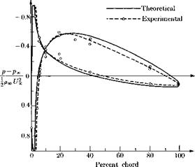
This formula was first given by Ackeret (1925). Comparisons of this simple result with experiments are shown in Fig. 5-8. It is seen that the first-order theory tends to underestimate the pressure and in general is

image83,image85

Fig. 5-8. Comparison of theoretical and experimental supersonic pressure distribution at M = 1.85 on a 10% thick biconvex airfoil at 0° angle of attack.

less accurate than that for incompressible flow. The deviation near the trailing edge is due to shock wave-boundary layer interaction which tends to make the higher pressure behind the oblique trailing-edge shocks leak upstream through the boundary layer.

The much greater mathematical simplicity of supersonic-flow problems than subsonic ones so strikingly demonstrated in the last two sections is primarily due to the absence of upstream influence for M > 1. Hence the flows on the upper and lower sides of the airfoil are independent and there is no need to separate the flow into its thickness and lifting parts. In later chapters cases of three-dimensional wings will be considered for which there is interaction between the two wing sides over limited regions.

Thin Airfoils in Supersonic Flow

Aerodynamics of Wings and Bodies

The manuscript of this book has gradually evolved from lecture notes for a two-term course presented by the authors to graduate students in the M. I.T. Department of Aeronautics and Astronautics. We shared with some colleagues a concern lest the essential content of classical aerodynamic theory—still useful background for the practice of our profession and the foundation for currently vital research problems—be squeezed out of the aeronautical cur­riculum by competition from such lively topics as hypersonic fluid mechanics, heat transfer, nonequilibrium phenomena, and magnetogasdynamics. We sought efficiency, a challenge to the enthusiasm of modern students with their orientation toward scientific rigor, and the comprehensiveness that can ac­company an advanced point of view. Our initial fear that certain mathematical complexities might submerge physical understanding, or obscure the utility of most of these techniques for engineering applications, now seems unwarranted. The course has been well-received for three years, and it has made a noticeable impact on graduate research in our department.

We are able to offer a textbook that has successfully met its preliminary tests. We have tried to keep it short. Problems and extended numerical demonstra­tions are omitted in the interest of brevity. We believe that the instructor who essays the pattern of presentation suggested here may find it stimulating to devise his own examples. It is also our hope that working engineers, with a need for the results of modern aerodynamic research and a willingness to accept new analytical tools, will derive something of value.

There is no shortage of books on aerodynamic theory, so let us point to two threads which make this one certainly distinct and possibly an improvement. The first is the realization that the method of matched asymptotic expansions, developed primarily by Kaplun and Lagerstrom, provides a unifying framework for introducing the boundary-value problems of external flow over thin wings and bodies. Not always an unavoidable necessity nor the clearest introduction to a new idea, this method nevertheless rewards the student’s patience with a power and open-ended versatility that are startling. For instance, as apparently first realized by Friedrichs, it furnishes a systematic, rigorous explanation of lifting-line theory—the only approach of its kind which we know. In principle, every approximate development carried out along this avenue implies the possibility of improvements to include the higher-order effects of thickness, angle of attack, or any other small parameter characterizing the problem.

Our second innovation is to embrace the important role of the high-speed computer in aerodynamics. Analytical closed-form solutions for simple flow models are certainly invaluable for gaining an understanding of the physical and mathematical structure of a problem. However, rarely are these directly applicable to practical aerodynamic configurations. For such, one usually has to resort to some approximate or numerical scheme. Theoretical predictions are becoming increasingly important as a practical tool supplementing wind-tunnel measurements, in particular for the purpose of aerodynamic optimization taking advantage of the gains to be realized, for example, by employing unusual plan –

form shapes or camber distributions, from imaginative use of wing-body inter­ference, adoption of complicated multiplane lifting surfaces, etc. We have, accordingly, tried to give adequate prominence to techniques for loading pre­diction which go far beyond the more elegant solutions at the price of voluminous routine numerical computation.

The plan of presentation begins with a short review of fundamentals, followed by a larger chapter on in viscid, constant-density flow, which recognizes the special character of that single division of our subject where the exact field differential equation is linear. Chapter 3 introduces the matched asymptotic expansions, as applied to one situation where physical understanding is attained with a minimum of subtlety. Chapter 4 warns the reader about the limitations and penalties for neglecting viscosity, and also illustrates the Kaplun-Lagerstrom method in its most powerful application. Thin airfoils in two dimensions and slender bodies are then analyzed. Three-dimensional lifting surfaces are treated in extenso, proceeding from low to high flight speeds and from single, planar configurations to general interfering systems. Chapter 12 attacks the especially difficult topic of steady transonic flow, and the book ends with a brief review on unsteady motion of wings. Only the surface is scratched, however, in these last two discussions.

Although we closely collaborated on all parts of the book, the responsibility for the initial preparation fell on Marten Landahl for Chapters 3, 4, 5, 6, 8, 9, 10, and 12, and on Holt Ashley for Chapters 1, 2, 7, 11, and 13. The first three groups of students in departmental courses 16.071 and 16.072 furnished in­valuable feedback as to the quality of the writing and accuracy of the develop­ment, but any flaws which remain are attributable solely to us.

We recognize the generous assistance of numerous friends and colleagues in bringing this project to fruition. Professor Milton VanDyke of Stanford Uni­versity and Arnold Kuethe of the University of Michigan most helpfully went over the penultimate draft. There were numerous discussions with others in our department, among them Professors Shatswell Ober, Erik Mollo-Christensen, Judson Baron, Saul Abarbanel, and Garabed Zartarian. Drs. Richard Kaplan and Sheila Widnall assisted with preliminary manuscript preparation and class­room examples. Invaluable help was given in the final stages by Dr. Jerzy Kacprzynski with the proofreading and various suggestions for improvements. The art staff of Addison-Wesley Publishing Company drew an excellent set of final figures. Typing and reproduction of the manuscript were skillfully handled by Mrs. Theodate Cline, Mrs. Katherine Cassidy, Mrs. Linda Furcht, Miss Robin Leadbetter, and Miss Ruth Aldrich; we are particularly appreciative of Miss Aldrich’s devoted efforts toward completing the final version under trying circumstances. Finally, we wish to acknowledge the support of the Ford Founda­tion. The preparation of the notes on which this book is based was supported in part by a grant made to the Massachusetts Institute of Technology by the Ford Foundation for the purpose of aiding in the improvement of engineering education.

Подпись: H.A., M.T.L. Cambridge, Massachusetts May 1965

Nonplanar Lifting Surfaces in Supersonic Flow

For analyzing the corresponding problem by linearized theory at super­sonic Mach numbers, we rely entirely on the technique of supersonic aerodynamic influence coefficients (AIC’s) and present only the general outlines of a feasible computational approach. Their only special virtue over other techniques is that they have been practically and successfully mechanized for a variety of steady and unsteady problems.

It should be pointed out first that there exists a formula for a supersonic pressure doublet analogous to the one that has been worked with in the preceding section [see Watkins and Berman (1956)]. This is quite difficult for manipulation, however, because of the law of forbidden signals and other wavelike discontinuities which occur. As a result, even the case of a planar lifting surface at supersonic speed has not been worked through completely and in all generality using pressure doublets. Rather, the problem has been handled by the sorts of special techniques described in Chapter 8. Examples of numerical generalization for arbitrary distribu­tions of incidence will be found in Etkin (1955), Beane et al. (1963), and Pines et al. (1955).

For nonplanar wings, the method of AIC’s has been developed and mechanized for the high-speed computer, but only in cases where two or
more individually-plane surfaces intersect or otherwise interfere. Thus a three-dimensional biplane, T-tail or V-tail can be handled, but ring or channel wings remain to be studied.

In preparation for the interference problem, let us describe more thor­oughly the procedure for a single surface that was outlined in Section 8-5. For simplicity, let the trailing edges be supersonic; but in the case of a subsonic leading edge the forward disturbed region of the x,«/-plane is assumed to be extended by a diaphragm, where a condition of zero pressure (or potential) discontinuity must be enforced. This situation is illustrated in Fig. 11-6.

For the disturbance potential anywhere in z > 0+, (8-6) gives

The region 2 is the portion of the wing plus diaphragm area intercepted by the upstream Mach cone from (x, y, z). When z —» 0+ so that <p is being calculated for a point P on the upper wing surface, 2 reduces to the area between the two forward Mach lines (see the figure).

Let us restrict ourselves to the lifting problem and let the wing have zero thickness. We know w(xu yi) from the given mean-surface slope over that portion of 2 that does not consist of diaphragm; on the latter, w is unknown but a boundary condition ip = 0 applies. As illustrated in Figs. 8-15 and 8-16, let the wing and diaphragm be overlaid to the closest possible approximation with rectangular elementary areas (“boxes”) having a chordwise dimension bi and spanwise dimension bx/B. In (11-29), introduce the transformation [cf. Zartarian and Hsu (1955)]

One thus obtains something of the form

This simultaneously employs dimensionless independent variables and converts all supersonic flows to equivalent cases at M = /2. The Mach lines now lie at 45° to the flight direction. The elementary areas, which had their diagonals parallel to the Mach lines in the x,//-plane, are thus deformed into squares.

Next let it be assumed that w is a constant over each area element and equal to the value wVtlI at the center. Both’ v and ц are integers used to count the positions of these areas rearward and to the right from v = 0 and p = 0 at the origin of coordinates. With this further approximation, the potential may be written

v((, «>».А. ЛЇ, v, Г), (П-32)

v, n

where the summation extends over all boxes and portions of boxes in the forward Mach cone. The definition of Ф„і(, as an integral over an area element is fairly obvious. For example, for a complete box

("-[8]/2) y/(n — £i)2 — [(m — rji)2 + l2]

This can easily be worked out in closed form. The computation is mech­anized by choosing £, ri (and possibly f) to be integers, corresponding to the centers of “receiving boxes. ” Thus, if we choose £ = n, ij = m, f = l, we get

where p. = m — n, v = n ~ v. (Special forms apply for combinations of v, //, l on the upstream Mach-cone boundary, which may be determined by taking the real part of the integral. Also Фу;;,; = 0 when is imaginary throughout the range of integration.)

In a similar way, we can work out, for the vertical and horizontal velocity components in the field at a point (n, m, l), expressions of the following forms:

v(n, m, l) = ^2

v. ft

w(n, m, l) = "22 wVtliWytfi, t

The AIC’s V and W involve differentiation of the Фц,^,і formula with respect to q and f, respectively, but they can be worked out without difficulty.

Now to find the load distribution on a single plane surface, we set l = 0 and order the elementary areas from front to back in a suitable way. The values of disturbance potentials at the centers of all these areas can then be expressed in the matrix form

Wn. rni = – ^[Ф?,ї. о]{«*,,}• (11-36)

A suitable ordering of the areas consists of making use of the law of for­bidden signals to assure that all numbers in Фу^.о are zero to the left and below the principal diagonal. It is known that <pn, m = 0 at all box centers on the diaphragms, whereas w„i(1 is given at all points on the wing. The former information can be used to solve successively for the values of at the diaphragm, the computation being progressive and never requiring the inversion of a matrix.

Once ге„і(1 is known for all centers on the wing and diaphragm, the complete distribution of y> may be determined. From this, we can calculate the pressure distribution (which is antisymmetrical top to bottom) by the relatively inaccurate process of numerical differentiation. If only lift, moment, pressure drag, or some other generalized forces are needed, however, we find that these can be expressed entirely in terms of the potential discontinuity over the surface and along the trailing edge. Hence, the differentiation step can be avoided. Zartarian (1956) and Zar – tarian and Hsu (1955) provide many details.

Turning to the interfering surfaces, we illustrate the method by two examples. 1

Fig. 11-7. Two interfering-plane supersonic wings with attached diaphragms. (Mach lines are at 45° in £-, 7)-, p-coordinates.)

exercised in setting up the interference problem. We have found that the best way to avoid paradoxes is to focus on the two conditions:

(a) The streamlines must be parallel to the mean surface over the area of each wing.

(b) A<p = 0 must be enforced over each diaphragm (Дp = 0 on wake diaphragms).

These can best be handled in the biplane case by placing additional sources over each wing-diaphragm combination, whose purpose is to cancel the upwash induced over one particular wing area due to the presence of the other wing. There is no need to be concerned with interfering upwash over the diaphragms, since the diaphragm is not a physical barrier and the interference upwash there does not cause any discontinuity of potential.

Having placed suitable patterns of square area elements over Sy and Sl, we can write for the upwash induced at wing boxes on Sy due to the presence of Sl :

nij d Г) — (11—37)

V. M

The summation here extends over all wing and diaphragm boxes on Sl that can influence point (n, m, d). In a similar way, reasons of antisym­metry in the flow field produced by Sy lead to the upwash generated at wing box n, m, 0 on Sl due to Sy:

wLy(n, m, 0) = ^ (wc/),,MW7,?,(_d), (ll-38a)

or

{wlu} wing = [Wi7,5,(_d)]{«!c/}. (ll-38b)

only

When writing the matrix formulas for <py and <pl, Wul and wlv must be subtracted from the upwash that would be present at wing boxes on

Su and Sl, respectively, in the absence of the interfering partner. Thus we obtain

Wu} = — ^ [Фг. д,о](0"£/} — (11-39)

where the last column covers wing and diaphragm boxes but zeros are inserted for the latter. Similarly,

{<Pl} = — ^ о]({и>п} — {w*Lu})- (11-40)

Making appropriate substitutions for wul* and iolu*, we get

M = -|fc, ol(W – lWb, d]{wL} (ll-41a)

Ш = -^[4f,;,oKW – IWlu-d)IW), (ll-41b)

where the meaning of the notation for W* is obvious in the light of the foregoing remarks.

We now have a set of coupled equations in <p and w. The values of <p are equated to zero at all diaphragm boxes, whereas w is known at all wing boxes, so the system is determinate. A solution procedure, at least in principle, is straightforward.

2. Intersecting Vertical and Horizontal Stabilizers. Surfaces that inter­fere but are not parallel present no new conceptual difficulties. Once again, the source sheet representing the flow on one side of either surface is analyzed as if the other were not there, except that the mean-surface “normal-wash ” distribution must be modified to account for interference.

Thus, consider the empennage ar­rangement shown in Fig. 11-8. Dia­phragms are shaded. The rightward sidewash at Sy due to Su and its diaphragm is

PVh(w, 0, l) = (WH)iMi^V. M,L (ll-42a)

Fig. 11-8. Intersecting supersonic surfaces.

Here fl = m — д = 0 — ц = —fi. The matrix abbreviation is

{wvh} = [кї,_іи, г]{№н}-

(ll-42b)

In a similar way, we find

wnv(n, m, 0) = — У] (уу)^,і^ї,-г, т

v, l

(ll-43a)

or

(why) = — [Vv,~l, m]{vv} ■

(ll-43b)

The potential formulas can then be written as follows and solved by substitutions like those discussed in the case of the biplane:

{ph} = — ^ I^if. n.oKW} — {whv}),

(ll-44a)

{^v} = — ^ [%,<uKW} — {vvh})-

(ll-44b)

Other supersonic interference problems can be handled in a similar manner. In all cases, a computational scheme can be found to make the solutions for the lifting pressures a determinate problem. Together with some numerical results, a list of references reporting progress towards mechanization of the foregoing supersonic methods will be found in Ashley, Widnall, and Landahl (1965).

12

Circulation and the Topology of Flow Regimes

Most of the theorems and other results stated or derived in preceding portions of the chapter refer to finite bodies moving through a finite or infinite mass of liquid. If these bodies have no holes through them, such a field is simply connected in the sense that any closed circuit can be shrunk to a point or continuously distorted into any other closed circuit without ever passing outside the field.

A physical situation of slightly greater complexity, called doubly con­nected, is one where two, but no more than two, circuits can be found such that all others can be continuously distorted into one or the other of them. Examples are a single two-dimensional shape, a body with a single penetrating hole, a toroid or anchor ring, etc. Carrying this idea further, the flow around a pair of two-dimensional shapes would be triply con­nected, etc.

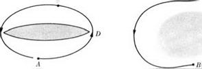
In the most general flow of a liquid or gas in a multiply connected region, Ф is no longer a single-valued function of position, even though the boundary conditions are specified properly as in the simply connected case. Turning to Fig. 2-6, let Фа be the specified value of the velocity potential at point A and at a particular instant. Then Фя can be written either as

image46

or as

Фв2 = фл + [ Q • ds. (2-92)

Jadb

These two results will not necessarily be equal, since we cannot prove the identity of the two line integrals when the region between them is not entirely occupied by fluid. As a matter of fact, the circulation around the closed path is exactly

Г = <£ Q • ds = Фд2 — ФВі. (2-93)

JADBCA

It is an obvious result of Stokes’ theorem that Г is the same for any path completely surrounding just the body illustrated. Hence the differ­ence in the values of Ф taken between paths on one side or the other always turns out to be exactly Г, wherever the two points A and В are chosen.

Until quite lately it was believed that, to render constant-density fluid motion unique in a multiply connected region, a number of circulations must be prescribed which is one less than the degree of connectivity. A forthcoming book by Hayes shows, however, that more refined topological concepts must be employed to settle this question. He finds that the indeterminacy is associated with a topological property of the region known as the Betti number. Since the mathematical level of these ideas exceeds what is being required of our readers, we confine ourselves to citing the reference and asserting that it confirms the correctness of the simple examples discussed here and in the following section.

Consider the motion of a given two-dimensional figure S with Г = 0. A certain set of values of ЗФ/дп on S can be satisfied by a velocity potential representing the noncirculatory flow around the body. To this basic flow it is possible to add a simple vortex of arbitrary strength Г for which one

Circulation and the Topology of Flow Regimes

В


C


s


Fig. 2-6. Circuit drawn around a two – Fig. 2-7. An illustration of the circuit dimensional shape surrounded by fluid, implied in Eq. (2-94).


image47

of the circular streamlines has been transformed conformally into precisely the shape of S. The general mapping theorem says that such a transforma­tion can always be carried out. By the superposition, a new irrotational flow has been created which satisfies the same boundary conditions, and it is obvious that uniqueness can be attained only by a specification of Г.

Leaving aside the question of how the circulation was generated in the first place, it is possible to prove that Г around any such body persists with time. This can be done by noting that the theorem of Kelvin, (1-12), is based on a result which can be generalized as follows:

image48(2-94a)

The fluid here may even be compressible, and A and В are any two points in a continuous flow field, regardless of the degree of connectivity. See Fig. 2-7. If now we bring A and В together in such a way that the closed path is not simply connected, and if we assume that there is a unique relation between pressure and density, we are led to

image49(2-94b)

Let us now again adopt the restriction to constant-density fluid and examine the question of how flows with multiply connected regions and nonzero circulations might be generated. We follow Kelvin in imagining at any instant that a series of barriers or diaphragms are inserted so as to make the original region simply connected by the specification that no path may cross any such barrier. Some examples for which the classical results agree with Hayes are shown in Fig. 2-8.

The insertion of such barriers, which are similar to cuts in the theory of the complex variable, renders Ф single-valued. We recall the physical interpretation [cf. (2-15)]

image50

Fig. 2-8. Three examples of multiply connected flow fields, showing barriers that can be inserted to make Ф unique. In (a) and (b), the shaded shapes are two­dimensional.

of Ф as the impulsive pressure required to generate a flow from rest. If such impulsive pressures are applied only over the surfaces of the bodies and the boundary at infinity in regions like those of Fig. 2-8, a flow without circulation will be produced. But suppose, additionally, that discontinuities in P of the amount

ДР = —p ДФ = – рГ (2-96)

are applied across each of the barriers. Then a circulation can be produced around each path obstructed only by that particular barrier. The genera­tion of a smoke ring by applying an impulse over a circular area is an obvious example. Note that ДФ (or Г) is constant all over any given barrier, but the location of the barriers themselves presents an element of arbi­trariness.

Slender-Body Theory

5- 1 Introduction

We shall now study the flow around configurations that are “slender” in the sense that all their crosswise dimensions like span and thickness are small compared to the length. Such a configuration could, for example, be a body of revolution, a low-aspect ratio wing, or a low-aspect ratio wing-body combination. The formal derivation of the theory may be thought of as a generalization to three dimensions of the thin airfoil theory; however, the change in the structure of the inner solution associ­ated with the additional dimension introduces certain new features into the problem with important consequences for the physical picture.

The simplest case of a nonlifting body of revolution will be considered first in Sections 6-2 through 6-4 and bodies of general shape in Sections 6-5 through 6-7.

6- 2 Expansion Procedure for Axisymmetric Flow

We shall consider the flow around a slender nonlifting body of revolution defined by

r = R{ x) = eR(x) (6-1)

for small-values of the thickness ratio e. For steady axisymmetric flow the differential equation (1-74) for Ф reads

2

(a2 – Ф2)ФХХ + (a2 – Ф?)ФГГ + у Фг – 2ФХФГФХГ = 0, (6-2)

where

a2 = a2 – (ФI + Фг2 – Ul). (6-3)

The requirement that the flow be tangent to the body surface gives the following boundary condition:

~ _ e dR r _ ед (6-4)

Фх ах

We shall consider an outer expansion of the form

Подпись: (6-5)Ф° = f7„[z + бФЇ(ж, r) – f е2Ф2(ж, г) + ■ • • ]

99

and an inner expansion

Ф* = UK[x + еФ(х, f) + е2Фl(x, ?) + •■•], (6-6)

where

f = r/e. (6-7)

As in the thin airfoil case Ф) must be a function of x, only, because other­wise the radial velocity component

U, = Ф* = £/„[ФІг + еФг? + • • • ] (6-8)

will not vanish in the limiting case of zero body thickness. Substituting (6-6) into (6-2) and (6-3) and retaining only terms of order e°, we obtain

Фггг + г Фгг = 0. (6-9)

Slender-Body Theory Подпись: (6-Ю)

r

Подпись:The solution of (6-9) satisfying (6-10) is easily shown to be ФІ = EE’In г + Ых),

Slender-Body Theory Slender-Body Theory

in which the function t/2 must be found by matching to the outer flow. From (6-11) it follows that the radial velocity component is

we find that Ф°г must be zero as r —» 0. The only solution for Ф° that will, in addition, satisfy the condition of vanishing perturbations at in­finity, is a constant which is taken to be zero. The perturbation velocities in the outer flow are thus of order e2 as compared to e in both the two­dimensional and finite-wing cases. That the flow perturbations are an order of magnitude smaller for a body of revolution is reasonable from a physical point of view since the flow has one more dimension in which to get around the body.

Since Ф° = 0 it follows by matching that also Ф) = 0. This will have the consequence that all higher-order terms of odd powers in e will be zero, and the series expansion thus proceeds in powers of e2. With Ф? = 0, substitution of the series for the outer flow into (6-2) and (6-3) gives
for the lowest-order term

(1 – M2)Ф°2хх + ~ ФІг + Фirr = 0. (6-14)

Slender-Body Theory Подпись: іJ°r = Ф°г = + 0(€3). Г xO „ Фгг = as r —» 0 r lim (гФІг) =5= RR'- Slender-Body Theory

The matching of the radial velocity component requires according to (6-12) that in the limit of r —> 0

The boundary condition at infinity is that Ф£х and Ф£, vanish there. Matching of Ф2 itself with Ф2 as given by (6-11) yields

<?2(ж) = lim [Ф2 — RR’ In r] + RR’ In e. (6-17)

r—>0

The last term comes from the replacement of f by r/e in (6-11). It follows that the inner solution is actually of order e2 In e rather than e2 as was assumed in the derivation. However, from a practical point of view, we may regard In e as being of order unity since In e is less singular in the limit of € —> 0 than any negative fractional power of e, however small.

Подпись: Cv = Slender-Body Theory Подпись: (6-18)

In calculating the pressure in the inner flow it is necessary to retain some terms beyond those required in the thin-airfoil case. By expanding (1-64) for small flow disturbances we find that

which, upon introduction of the inner expansion, gives

Cp = —є2[2Ф2і + (Фгг)2] + • • • (6-19)

The terms neglected in (6-19) are of order e4 In e, or higher.

As was done in the case of a thin wing, we introduce a perturbation velocity potential <p, in the present case defined as

Подпись: (6-20)<P = е2Фг.

The equations derived above then become for the outer flow

where S(x) = ttR2(x) is the cross-sectional area of the body. The pressure near the body surface is given by

CP = —(2<px + *?) (6-23)

to be evaluated at the actual position r (for r = 0 it becomes singular). From the result of the inner expansion it follows that in the region close to the body

<P ^ ^ S'(x) In r + g{x), (6-24)

where g(x) is related to <Ь(я) in an obvious manner.

In (6-24), the first term represents the effect of local flow divergence in the crossflow plane due to the rate of change of body cross-sectional area. According to the slender-body theory this effect is thus seen to be approximately that of a source in a two-dimensional constant-density flow in the – y, z-plane. Hence, the total radial mass outflow in the inner region is independent of the radius r, as is indeed implied in the boundary condition (6-22). The second term, g(x), contains the Mach number dependence and accounts for the cumulative effects of distant sources in a manner that will be further discussed in the next section.

Fundamentals of Fluid Mechanics

1- 1 General Assumptions and Basic Differential Equations

Four general assumptions regarding the properties of the liquids and gases that form the subject of this book are made and retained throughout except in one or two special developments:

(1) the fluid is a continuum;

(2) it is inviscid and adiabatic;

(3) it is either a perfect gas or a constant-density fluid;

(4) discontinuities, such as shocks, compression and expansion waves, or vortex sheets, may be present but will normally be treated as separate and serve as boundaries for continuous portions of the flow field.

The laws of motion of the fluid will be found derived in any fundamental text on hydrodynamics or gas dynamics. Lamb (1945), Milne-Thompson (1960), or Shapiro (1953) are good examples. The differential equations which apply the basic laws of physics to this situation are the following.[1]

1. Continuity Equation or Law of Conservation of Mass

image1(1-1)

where p, p, and T are static pressure, density, and absolute temperature.

Подпись: (1-2)Q = f/i + Vj + Wk

is the velocity vector of fluid particles. Here i, j, and к are unit vectors in the X-, y-, and г-directions of Cartesian coordinates. Naturally, com­ponents of any vector may be taken in the directions of whatever set of coordinates is most convenient for the problem at hand.

2. Newton’s Second Law of Motion or the Law of Conservation of Momentum

Подпись:DQ – _ Vp

Dt p

where F is the distant-acting or body force per unit mass. Often we can write

F = Vfi, (1-4)

where Я is the potential of the force field. For a gravity field near the surface of a locally plane planet with the «-coordinate taken upward, we have

Подпись: (1-5)F = – gk Я = — gz,

g being the gravitational acceleration constant.

3.

Подпись: _D Dt Fundamentals of Fluid Mechanics Подпись: (1-6)
image2

Law of Conservation of Thermodynamic Energy (Adiabatic Fluid)

Подпись: D P Dt Fundamentals of Fluid Mechanics Подпись: (1-7)
image3

Here e is the internal energy per unit mass, and Q represents the absolute magnitude of the velocity vector Q, a symbolism which will be adopted uniformly in what follows. By introducing the law of continuity and the definition of enthalpy, Л = e + р/р, we can modify (1-6) to read

Подпись: Ds Dt Подпись: 0, Подпись: (1-8)

Newton’s law can be used in combination with the second law of thermo­dynamics to reduce the conservation of energy to the very simple form

where s is the entropy per unit mass. It must be emphasized that none of the foregoing equations, (1-8) in particular, can be applied through a finite discontinuity in the flow field, such as a shock. It is an additional consequence of the second law that through an adiabatic shock s can only increase.

4. Equations of State

For a perfect gas,

p = RpT, thermally perfect gas ^

cP, c„ = constants, ealorieally perfect gas.

For a constant-density fluid, or incompressible liquid,

p = constant. (1-Ю)

In (1-9), cp and c„ are, of course, the specific heats at constant pressure and constant volume, respectively; in most classical gas-dynamic theory, they appear only in terms of their ratio У = cp/cv. The constant-density assumption is used in two distinct contexts. First, for flow of liquids, it is well-known to be an excellent approximation under any circumstances of practical importance, in the absence of cavitation. There are, moreover, many situations in a compressible gas where no serious errors result, such as at low subsonic flight speeds for the external flow over aircraft, in the high-density shock layer ahead of a blunt body in hypersonic flight, and in the crossflow field past a slender body performing longitudinal or lateral motions in a subsonic, transonic, or low supersonic airstream.

Transonic Small-Disturbance Flow

11- 1 Introduction

A transonic flow is one in which local particle speeds both greater and less than sonic speed are found mixed together. Thus in the lower transonic range (ambient M slightly less than unity) there are one or more super­sonic regions embedded in the subsonic flow and, similarly, in the upper transonic range the supersonic flow encloses one or more subsonic flow regions. Some typical transonic flow patterns are sketched in Fig. 12-1. Since in a transonic flow the body travels at nearly the same speed as the forward-going disturbances that it generates, one would expect that the flow perturbations are generally greater near M = 1 than in purely subsonic or supersonic flow. That this is indeed so is borne out by experi­mental results like those shown in Figs. 12-2 and 12-3, which show that the drag and lift coefficients are maximum in the transonic range. In the early days of high-speed flight, many doubted that supersonic aeroplanes could ever be built because of the “sonic barrier,” the sharp increase in drag experienced near M equal to unity.

Many of the special physical features, and the associated analytical difficulties, of a transonic flow may be qualitatively understood by con­sidering the simplest case of one-dimensional fluid motion in a stream tube. Combination of the Euler equation

and with the equation of continuity

і (pm = o,

where S(x) is the stream-tube area, yields after some manipulation

dp dS

pU2 S[1 – (C72/a2)]

This relation shows that for U/а — 1 the flow will resist with an infinite force any stream-tube area changes, i. e., it will effectively make the flow incompressible to gross changes in the stream-tube area (but not to curva­ture changes or lateral displacement of a stream-tube pattern). There­fore, the crossflow in planes normal to the free-stream direction will tend to be incompressible, as in the case of the flow near a slender body, so that much of the analysis of Chapter 6 applies in the transonic range to con­figurations that are not necessarily slender. This point will be discussed further below. It is evident that because of the stream-tube area constraint, there will be a tendency for a stronger cross flow within the stream tube and hence the effect of finite span will be maximum near M = 1. From (12-1) it also follows that in order to avoid large perturbation pressures and hence high drag one should avoid large (and sudden) cross-sectional area changes, which in essence is the statement of the transonic area rule discussed in Chapter 6. For the same reason one can see that the boundary layer can have a substantial influence on a transonic pressure distribution, since it provides a region of low-speed flow which is less "stiff” to area changes and hence can act as a “buffer” smoothing out area changes.

From such one-dimensional flow considerations, one practical difficulty also becomes apparent, namely that of wind tunnel testing at transonic speeds. Although a flow of M = 1 can be obtained in the minimum-area section of a nozzle with a moderate pressure ratio, the addition of a model, however small, will change the area distribution so that the flow no longer will correspond to an unbounded one of sonic free-stream speed. This problem was solved in the early 1950’s with the development of slotted – wall wind tunnels in which the wall effects are eliminated or minimized by using partially open walls.

The main difficulty in the theoretical analysis of transonic flow is that the equations for small-disturbance flow are basically nonlinear, in con­trast to those for subsonic and supersonic flow. This again may be sur­mised from equations like (12-1), because even a small velocity change caused by a pressure change will have a large effect on the pressure-area relation. So far, no satisfactory general method exists for solving the transonic small-perturbation equations. In the case of two-dimensional flow it is possible, through the interchange of dependent and independent
variables, to transform the nonlinear equations into linear ones in the hodograph plane. However, solutions by the hodograph method have been obtained only for special simple airfoil shapes and, again, two-dimen­sional flow solutions are of rather limited practical usefulness for transonic speeds. For axisymmetrie and three-dimensional flow, various approxi­mate methods have been suggested, some of which will be discussed below.

11- 2 Small-Perturbation Flow Equations

That the small-perturbation theory for sub – and supersonic flow breaks down at transonic speeds becomes evident from the linearized differential equations (5-29) and (6-21) for the perturbation potential, which in the limit of M —> 1 become

<Pzz = 0, for two-dimensional flow, (12-2)

і (pr + tfrr = 0, for axisymmetrie flow. (12-3)

Thus, both the inner and outer flows will be described by the same differ­ential equation, and it will in general not be possible to satisfy the boundary condition of vanishing perturbation velocities at infinity. For transonic flow it will hence be necessary to consider a different expansion that retains at least one more term in the equation for the first-order outer flow.

In searching for such an expansion we may be guided by experiments. By testing airfoils, or bodies of revolution, of the same shape but different thickness ratios (affine bodies) in a sonic flow one will find that, as the thickness ratio is decreased, not only will the flow disturbances decrease, as would be expected, but also the disturbance pattern will persist to larger distances (see Fig. 12-4).

This would suggest that the significant portion of the outer flow will recede farther and farther away from the body as its thickness tends towards zero. In order to preserve, in the limit of vanishing body thick­ness, those portions of the outer flow field in which the condition of vanishing flow perturbations is to be applied we must therefore “compress ” this (in the mathematical sense). Taking first the case of a two-dimen­sional airfoil with thickness but no lift, we shall therefore consider an expansion of the following form:

where S(x) is the cross-sectional area. The outer flow must therefore be equal to that around the equivalent body of revolution as in the slender- body case, and we have thus demonstrated the validity of the transonic equivalence rule resulting from the form of the first-order term in an asymptotic series expansion as the disturbance level «, and M2 — 1 [, both tend to zero. The approach followed is essentially that taken by Messiter (1957). A similar derivation was given by Guderley (1957).

There is no requirement on aspect ratio except that it should be finite so that 8 A —> 0 as e —> 0, in order for the outer flow to be axisymmetric in the limit. A consequence of this is that slender-body theory should provide a valid first-order approximation to lifting transonic flows for wings of finite (and moderate) aspect ratios. In Fig. 12-3 the slender-body value for the lift coefficient is compared with experimental results for a delta wing of A = 2. It is seen that the agreement is indeed excellent at M = 1.

For a wing of high aspect ratio, the first-order theory will provide a poor approximation for thickness ratios of engineering interest. A different expansion is then called for, which does not lead to an axisymmetric outer flow. We therefore introduce in the outer expansion

V = 8y, f = 8z, (12-38)

with 8 chosen as before, (12-11). This then gives the following equation for the first-order outer term:

The matching will prescribe the normal velocity on the wing projection on f = 0, which in view of (12-38) will have all spanwise dimensions reduced by the factor S. Thus, if the limit of e —» 0, and hence 5 —> 0,

is taken with the aspect ratio A kept constant, the projection in the

x, y-plane will have a reduced aspect ratio AS that will shrink to zero in the limit, and the previous case with an axisymmetric outer flow is then recovered. In this case we therefore instead consider the limit of e —> 0 with A —» oo in such a manner that

AS = K2 (12-40)

approaches a constant. The reduced aspect ratio will then be finite and equal to K2. The matching procedure now parallels that for the two­dimensional flow and the choice (12-17) for e gives the boundary condition

Фн(*. V, 0±) = ± U (12-41)

to be satisfied on the wing projection of reduced aspect ratio

K2 = t1I3AM2,3( 7 + 1)1/3 (12-42)

Thus, the solution in this case depends on two transonic parameters K1 and K2. The previous case, for which the transonic equivalence rule holds, may be considered the limiting solution when

K2 -» 0.

As the approach to zero is made the solution defined by (12-39) and (12-41) becomes, in the limit, proportional to K2nK2. The two-dimensional case described by (12-12)-(12-14), or (12-19)-(12-21), is obtained as the limit of

K2 —» oo.

The most general transonic small-perturbation equation is thus

[1 — M2 — M2{ 7 + 1 )<pz]<pxx + <Pyy + <Ргг = 0, (12-43)

with the boundary condition in case of a thin wing

4>z(x, y, 0±) = ±r ~ on wing projection Sw. (12-44) ox

The pressure is given by (12-21) for a thin wing and by

Cp = —2ipx – <p2y – v2 (12-45)

for a slender configuration.

12- 3 Similarity Rules

The first-order terms in the series expansion considered above provide similarity rules to relate the flow around affine bodies.[9] Taking first the two-dimensional case, we see from (12-18) that the reduced pressure coefficient

я [My+ 1)]1/3

Ьр ~ т2/3 Ьр

must be a function of x/c (c = chord) and the parameter

M2 – 1 M2 – 1

fM2(T + 1) ~~ [М2т(У + l)]2/3

only. This conclusion follows because the solution must be independent of scale (see Section 1-4) and К i is the only parameter that enters the boundary value problem defined by (12-12) and (12-15).

The total drag is obtained by integrating the pressure times the airfoil slope, which leads in a similar way to the result that

[M2{ 7 + 1)]1/3„

——

must be a function of Kx only. The additional factor of r enters because the slope is proportional to r. Of course, (12—48) holds only for the wave drag, so that in order to use it to correlate measurements, the friction drag must be subtracted out. Such an application to biconvex-airfoil drag measurements by Michel, Marchaud, and LeGallo (1953) is illustrated in Fig. 12-5. As may be seen, the drag coefficients for the various airfoil thicknesses, when reduced this way, fall essentially on one single curve, thus confirming the validity of (12—48), and hence the small-perturbation equations.

Transonic similarity rules for two-dimensional flow were first derived by von Kdrmdn (1947b) and Oswatitsch (1947). These rules also included the lifting case.

Rules for a slender body of revolution were formulated by Oswatitsch and Berndt (1950). There is an additional difficulty in this case associated with the logarithmic singularity at the axis. It follows from the formula­tion (12-26)-(12-30) for the outer flow and the matching to the inner flow
as given by (12-28) that, near the body,

$i = ^S'(aO lnp + £i(z).

The transonic parameter

M2 – 1 _ M2 – 1

Kl ~ eM*{7 + 1) M2r2(7 + 1)

thus enters into (ji only. By using (12-33) to calculate the pressure coeffi­cient we find that, on the body,

Cp = —2T2 {^S"(x) In [t2MVt~+7 R] + &'(*) + І(й’)2} * (12-51)

where R(x) = R(x)/t. Thus,

Cp = {— Cp + ^ S"(x) In [т2Мф + l]J (12-52)

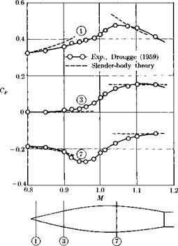
is a function of K and x/l only. An application of (12-52) to correlate the measured pressures on two bodies of different thickness ratios, carried out by Drougge (1959), is shown in Fig. 12-6. As may be seen, the correla­tion is almost perfect, except at the rearmost portions of the bodies where boundary layer separation occurs.

From (12-52) one can also construct an expression for the drag, as shown in the original paper by Oswatitsch and Berndt (1950). They found that ^ 1

D = t D– + ~ [S'(l)]2 In [t-WyTT] (12-53)

2P« UQoT

must be a function of Ki only.

Fig. 12-6. Correlation of pressure measurements on two bodies of revolution using the transonic similarity law (12-52). P = Cp + (l/ir)S" In (7 + 1). (Adapted from Drougge, 1959. Courtesy of Aeronautical Research Institute of Sweden.)

It is a fairly straightforward matter to construct corresponding simi­larity rules for configurations of low-to-moderate aspect ratios. For wings of large aspect ratios one obtains results of the same form as for the two­dimensional case, except that now the reduced quantities depend on the second transonic parameter

K2 = t1/3AM2/3( у + 1)1/3

as well as on K. The rules for three-dimensional wings were derived by Berndt (1950) and by Spreiter (1953).

Examples of Constant-Density Flows Where Circulation May Be Generated

An elementary illustration of the ideas of the foregoing section is pro­vided by a two-dimensional vortex pair. We work here in terms of real variables rather than the complex variable, although it should be obvious to those familiar with two-dimensional flow theory that the results we obtain could be more conveniently derived by the latter approach. Con­sider a pair of vortices, which are equal and opposite and may be thought of as wrapped around very small circular cylindrical cores which constitute the boundaries S (Fig. 2-9). This motion can be generated by applying a downward force per unit area

ДР = —p ДФ = рГ (2-97)

across the barrier shown in the picture. The total Kelvin impulse per

image51

Fig. 2-9. Two equal and opposite line Fig. 2-10. Vortex pattern simulating vortices separated a distance d. flow around a wing of finite span.

unit distance normal to the page is directed downward and may be written

£ = – j(prd), (2-98)

where j is a unit upward vector and d is the instantaneous separation of the vortex cores.

If, for instance, one of the two vortices is bound to a wing moving to the left with velocity t/„ while the other remains at rest in the fluid in the manner of a starting vortex, the force exerted by the fluid on the supporting bodies is

Fbody = ~ ~it= ~ Jt

= )PTjt(d) = pU„Tj. (2-99)

This may be recognized as the two-dimensional lift called for by the theorem of Kutta and Joukowsky.

A more complicated system of vortices is used as an indirect means of representing the influence of viscosity on the flow around a lifting wing of finite span (Fig. 2-10). For any one of the infinite number of elongated vortex elements, the Kelvin impulse is directed downward and equals

£ = —jp ДФ X [area]. (2-100)

The area here changes at a rate dependent on the forward speed C7„. The reaction to the force producing the increased impulses of the various vortices adds up to the instantaneous lift on the wing. Moreover, from the spanwise distribution of vortex strengths the spanwise distribution of lift is obtainable, and the energy in the vortex system is connected with the induced drag of the wing. It is evident that these vortices could not be generated in the first place except through the action of viscosity in pro­ducing a boundary layer on the wing, yet we can obtain much useful information about the loading on the system without actually attempting a full solution of the equations of Navier and Stokes.

2-Q Two-Dimensional, Constant-Density Flow: Fundamental Ideas

We now turn to the subject of two-dimensional, irrotational, steady or unsteady motion of constant-density fluid. We begin by listing a number of results which are well-known and may be found developed, for instance, in Chapters 5 through 7 of Milne-Thompson (1960). The combined condi­tions of irrotationality and continuity assure the existence of a velocity potential Ф(г, t) and a stream function Ф(г, t), such that

Q = V4> = V X (кФ). (2-101)

Here

r = xi + yj. (2-102)

Подпись:

Подпись: ЭФ _ ЭФ . u ~ dx ~ ay ’ Подпись: ЭФ _ _ 5Ф dy dx

If (2-101) is written out in component form, we obtain.

The latter equalities will be recognized as the Cauchy-Riemann relations. For constant-density fluid,

V. Q = V2$> (2-104)

is the volume divergence, whereas for a rotational flow,

V X Q = – кУ2Ф (2-105)

is the vorticity vector. Therefore, in the case under consideration,

V4 = 0 = V24>. (2-106)

Among other ways of constructing solutions to the two-dimensional Laplace equation, a function of either

Z = x + iy = re’9

(2-107)

Z = x — iy = re-‘9

(2-108)

alone will be suitable.[3] To be more specific, the Cauchy-Riemann relations are necessary and sufficient conditions for Ф and Ф to be the real and imaginary parts, respectively, of the same analytic function of Z. This function we call the complex potential,

Подпись: (2-109)■w (Z) = Ф + г’Ф.

Examples of Constant-Density Flows Where Circulation May Be Generated Подпись: (2-110) (2-111)

The following formulas for particle velocity and speed are easily derived:

The lines Ф = const and Ф = const form orthogonal networks of equi – potentials and streamlines in the x, у-plane, which is usually referred to as the Z-plane.

An interesting parallelism between the imaginary unit г = %/—l and the vector operator kx is discussed in Milne-Thompson (1960), and some readers may find it helpful to study this more physical interpretation of a quantity which has unfortunately been given a rather formidable name.

The fact that the complex potential is a function of a single variable has many advantages. Differentiation is of the ordinary variety and can be conveniently cascaded or inverted. Also, it makes little difference whether we operate with the functional relationship W(Z) orZ(W); many flows are more conveniently described by the latter.

We recall that many fundamental flow patterns are associated with simple singular forms of the complex potential. Thus In (Z) implies a point source or point vortex, 1/Z is a doublet, and Z“ corresponds to various fluid motions with linear boundaries meeting at angles related to a. A failure of one or more of the underlying physical assumptions occurs at the singular point location. Nevertheless, the singular solutions are useful in constructing flows of practical interest in regions away from their cen­ters. Forces and moments can be expressed in terms of contour integrals around the singularities and are therefore connected with residues at poles.

Examples of Constant-Density Flows Where Circulation May Be Generated Подпись: (2-112)

The complex potential is itself a kinematical concept. To find pressures and resultant forces in steady and unsteady flows, further information is required. Thus Bernoulli’s equation, (1-63), is our tool for pressure calcu­lation. The necessary quantities are taken from (2-111) and

where the operator on the right means to take the real part of the quantity in braces.

Examples of Constant-Density Flows Where Circulation May Be Generated Examples of Constant-Density Flows Where Circulation May Be Generated

For forces and moments on a single closed figure in steady flow, we have available the classical Blasius equations

where Mo is the counterclockwise moment exerted by the fluid on the profile about an axis through the origin, and C is a contour that surrounds the body but no other singularities of the flow field, if such exist. In the absence of external singularities, the contour may be enlarged indefinitely. Then if ‘W(Z) can be expanded into an inverse power series in Z, which is nearly always the case, we identify all forces as coming from the l/Z term and all moments as coming from the l/Z2 term. We conclude that an effective source or vortex, plus a uniform stream, will lead to a resultant force. Moreover, a doublet may give rise to a moment, as can certain other combinations of source-like and vortex-like singular solutions.
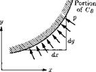
image52Fig. 2-11. Pressure force acting on a short segment of body surface in two­dimensional flow.

Подпись: However, Подпись: dFx — idFy = —pdy — ipdx = —ipdZ. Q2 . дФ nonessential p = —p 2 + dt_ + increment Подпись: (2-115)

In a limited way, (2-113) and (2-114) can be extended to apply to unsteady flows. The development follows Section 6.41 of Milne-Thompson (1960), but a restriction is required which is not carefully stated there. Let us consider a two-dimensional body whose position is fixed and whose contour does not change with time but which is in an accelerated stream U„(t) or otherwise unsteady regime. See Fig. 2-11. We derive the force equation and simply write down its analog for the moment. Let Cb be a contour coinciding with the fixed body surface. We note that

Подпись:p<W<№_ дФ 2 dZ dZ P dt ‘

The quantity labeled “nonessential increment” is dropped from (2-116) since even a time function will contribute nothing to the total force or moment. We substitute into (2-115)

dFx – і dFy = » I % (2-H7)

On the body surface,

Ф = Фв(<) (2-118)

independent of the space coordinates because of the assumed fixed position (i. e., the body is always an instantaneous streamline). Noting that the integration of force is carried out for a particular instant of time, we may write, following the contour Cb,

dw = <M> = dW = dZ, (2-119)

Подпись:Подпись: (2-121)ЭФ _ dW. d*B dt ~ dt +l dt ‘

The latter holds true because

W = Ф — г’Ф.

dZ + ip f *£dZ

CB dt

Подпись: F, Examples of Constant-Density Flows Where Circulation May Be Generated Подпись: (2-122)

Finally, we integrate around the contour С в and observe that the integral of the quantity d^fe/dt must vanish.

In this latter form the integrals are carried out around the contour C because each integrand is recognized as an analytic function of the variable of integration only, and contour deformation is permitted in the usual fashion. Of course, no pole singularities may be crossed during this de­formation, and branch points must be handled by putting suitable cuts into the field. The extended Blasius equation for moments in unsteady flow reads

M0 = – Re j| £ Z (^f )2 dZ + p I £ fw + itB(t)]Z dzj • (2-123)

Here the second contour may not be deformed from Cb since Z is not an analytic function of Z.

Подпись: Ф(ж, у; t) Подпись: 2ir J cB Examples of Constant-Density Flows Where Circulation May Be Generated Подпись: (2-124)

We close this section by setting down, without proof, the two-dimen­sional counterpart of (2-28). For an arbitrary field point x, y, this theorem expresses the velocity potential as follows:

Here the fluid must be at rest at infinity; line integration around the body contour is carried out with respect to dummy variables x, y\ and

The natural logarithm of r is the potential of a two-dimensional line source centered at point X, y. When differentiated with respect to out­ward normal n, it is changed into a line doublet with its axis parallel to n.

2-10 Two-Dimensional, Constant-Density Flow:

Conformal Transformations and Their Uses

A consequence of the mapping theorem of Riemann is that the exterior of any given single closed figure, such as an airfoil, in the complex Z-plane can be mapped into the exterior of any other closed figure in the f-plane by an analytic relation of the form

£ = /(f)- (2-126)

See Fig. 2-12. It is frequently convenient to choose a circle for the f-figure. The angle between any two intersecting lines is preserved by the trans­formation; for example, a set of orthogonal trajectories in one plane also turns out to be a set in the other. If the point at infinity is to remain unchanged, the transformation can always be expanded at large distances into something of the form

2 = f + y + p + — -> (2-127)

where the a„ are complex constants.

image53

Fig. 2-12. An illustration of the Z – and f-planes connected through conformal transformation.

It is occasionally pointed out that a special case of conformal trans­formation is the complex potential itself, (2-109), which can be regarded as a mapping of the streamlines and equipotentials into а (Ф + id’j-plane, where they become equidistant, horizontal and vertical straight lines, respectively.

The practical significance of the mapping theorem is that it can be used to transform one irrotational, constant-density flow’Wi(f) with elementary

boundaries into a second flow

W(Z) = ‘Wi[f1(Z)]l (2-128)

which has a more complicated boundary shape under the control of the transformer. Contours of engineering interest, such as a prescribed wing section, are readily obtained by properly choosing the function in (2-126). Conditions far away from the two figures can be kept the same, thus allowing for a prescribed flight condition.

Velocities, and consequently pressures, can be transformed through the relation

£ and – q being the real and imaginary parts of f, respectively. The equa­tions of Blasius can be employed to determine resultant force and moment in either of the two planes, and the transformation of variable itself is helpful when determining this information for the Z-figure. To provide starting points, many elementary complex potentials are known which characterize useful flows with circular boundaries.

Several transformations have proved either historically or currently valuable for constructing families of airfoil shapes and other two-dimen­sional figures with aeronautical applications. The reader is presumed to be familiar with the Joukowsky transformation, and much can be done with very minor refinements to the original investigations of Kutta and Joukowsky. No effort is made to expose in detail the various steps that have been carried out by different investigators, but we do list below a number of the more important transformations and something about their consequences.

1. The Joukowsky-Kutta Transformation

Z=[ + j – (2-131)

Here l is a positive real constant, and the so-called singular points of the transformation where the dZ/d{ — 0 are located at f = ±1, correspond­ing to Z = ±21. When applied to suitably located circles in the f-plane, (2-131) is well known to produce ellipses, flat plates, circular arc profiles of zero thickness, symmetrical and cambered profiles with their maximum thickness far forward and with approximately circular-arc camber lines.

The shape obtained actually depends on the location of the circle relative to the aforementioned singular points. A cusped trailing edge is produced by passing the circle through the singular point on the downstream side of the circle.

2. The von Mises Transformations. These transformations are special cases of the series, (2-127), in which it is truncated to a finite number of terms:

Z=f + ^ + — -+ £- (2-132)

S f”

When an airfoil is being designed, the series is constructed by starting from the singular point locations at

and subsequently integrated in closed form. By the rather laborious process of trial-and-error location of singular points, many practical air­foils were developed during the 1920’s. It is possible to adjust the thick­ness and camber distributions in a very general way. Interesting examples of von Mises and other airfoils will be found discussed in a recent book by Riegels (1961).

3. The von Karman-Trefftz Transformation. This method derives from a scheme for getting rid of the cusp at the trailing edge, produced by the foregoing classes of transformations, and replacing it by a corner with a finite angle t. To see how it accomplishes this, consider a trans­formation with a singular point at f = fo, corresponding to a point Z = Z0. In the vicinity of this particular singular point, it is easy to show that the transformation can be approximated by

Z-Z0= Alt – ГоГ, n > 1, (2-135)

where A is some complex constant. Evidently, the quantity

S = – ~Ai’ – f°r" (2“136)

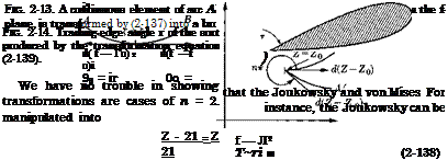
vanishes at the point for n > 1, as it is expected to do. Let r0 and в0 be the modulus and argument of the complex vector emanating from the point f0- Equation (2-136) can be written

Подпись: (2-137)d(Z – Z0) = nAr3-V("-1)*0d(r – fo).

image55

This is to say, the element of arc d((" — f0) is rotated through an angle (n — 1)0O in passing from the ("-plane to the Z-plane, if we overlook the effect of the constant A which rotates any line through ("0 by the same amount. Figure 2-13 demonstrates what this transformation does to a continuous curve passing through the point (" = ("0 in the ("-plane. By proper choice of n, the break in the curve which is produced on the Z-plane can be given any desired value between ir and 27t.

Подпись: Z - 21 Z A 21 Подпись: 2—(r/ir) Подпись: (2-139)

Yon K&rm&n and Trefftz (1918) suggested replacing (2-138) as follows:

As in Fig. 2-14, the outer angle between the upper and lower surfaces of the airfoil at its trailing edge (T. E.) is now (2тг — т), so a finite interior angle has been introduced and can be selected at will.

In a similar fashion a factor

can be included in the von Mises equation (2-134). Then if the circle in the f-plane is passed through the point f = f,,T E, an adjustable trailing edge is provided for the resulting profile.

4. The Theodor sen Transformation[4] Theodorsen’s method and the several extensions which have been suggested for it are capable of con­structing the flow around an airfoil or other single object of completely arbitrary shape. All that is needed is some sort of table or equation pro­viding the ordinates of the desired figure. The present brief discussion will emphasize the application to the airfoil.

The transformation is actually carried out in two steps. First the airfoil is located in the Z-plane as close as possible to where a similarly shaped Joukowsky airfoil would fall. It can be proved that this will involve locating the Joukowsky singular points Z = ±2Z halfway between the nose and the trailing edge and their respective centers of curvature. (Of course, if the trailing edge is pointed, the singularity Z — —21 falls right on it.) By applying Joukowsky’s transformation in reverse, the airfoil is transformed into a “pseudocircle” in the Z’-plane

Z = Z> + D • (2-140)

z
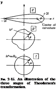
Подпись:The second procedure is the conver­sion of the pseudocircle to an exact circle centered at the origin in the Z’-plane by iterated determination of the coefficients in the transforma­tion series

Z’= fexpfe^). (2-141)

i=i 1 7

Here the Cn are complex constants. The two steps of the process are illustrated in Fig. 2-15.

Let us consider the two steps in a little more detail. We write

Z = x + iy, (2-142)

Z> = іеФ+іч, (2-143)

That is, the argument of Z’ is

denoted by в and its modulus is le*. It is not difficult to derive the direct and inverse relationships between the coordinates of the airfoil and pseudocircle:

Подпись:(2-144)

Подпись: (2-145) (2-146) 2 sin2 в = p + л/p2 + (y/l)2
2 sinh2 ф = — p – f – Vp2 + (y/l) 2>

where

image58

Note that ф will be quite a small number for profiles of normal thickness and camber.

The function ф(в) for the pseudocircle may be regarded as known at as many points as desired. We then write

J – = Д0еіф = и*°еіф. (2-147)

For points on the two contours only, the transformation, (2-141), can be manipulated as follows:

Z’ le^+i8

J = = exP к* – *o) + W – Ф)}, (2-148)

Z’ = f exp [{ф — фо) + i(8 — ф)] = f exp ^ (2-149)

Theodorsen (1931) adopted the symbol e to denote the shift in argument going from the Z’- to the ("-plane,

Подпись:€ ~ ф — в ОГ ф = в + €.

Подпись:Cn ~ “1“

An. Bn.

—– COS пф І———- sm пф

Д

п туп

0 Ло J

Bn, і An • ,

— cos пф H—— sm пф

Д

п ТУП

о Ло J

These two equations imply that (ф — Фа) and e are conjugate quantities. They are expressed as Fourier series in the variable Ф, so that the standard formulas for individual Fourier coefficients could be employed if these quantities were known in terms of ф. Moreover, the conjugate property

can be used to relate the functions e and ф directly,

as follows:

■<*’>- Li *<+>“*(* 2*

^ёф,

(2-154)

Ф(Ф’) = ^ + ~fo е(ф) cot^

ф’)ёф.

(2-155)

In actuality, only ф(в) is available to begin with; 0 can be regarded as a first approximation to ф, however, and (2-154) employed to get a first estimate of e. Equation (2-150) then yields an improved approximation to ф and to ф(ф), so that (2-154) may be used in an iterative fashion to obtain converged formulas for the desired quantities. For typical airfoils it is found that this process converges very rapidly, and the numerical integration of (2-154) need be iterated only once or twice. Of course, it is necessary to be careful about the pole singularity at ф = ф’.

As described in the references, Theodorsen’s so-called e-method has many uses in the theory of low-speed airfoils. For instance, one can gener­ate families of profiles from assumed forms of the function е(ф). Approxi­mate means have been developed, starting from an airfoil of known shape and pressure distribution, for adjusting this pressure distribution in a desired fashion. This scheme formed the basis for the laminar flow profiles

image59

Fig. 2-16. Comparison between predicted and measured pressure distribution over the upper and lower surfaces of a Clark Y airfoil at an effective geometrical incidence of —1 deg 16 min. Theoretical incidence chosen to give approximately the measured value of total lift. [Adapted from Theodorsen (1931).]

which played such an important role in the early 1940’s. Their shapes sustain a carefully adjusted, favorable pressure distribution to assure the longest possible laminar run prior to transition in the boundary layer. In wind tunnel tests, they achieve remarkable reductions in friction drag; unfortunately, these same reductions cannot usually be obtained in engi­neering practice, and some of the profiles have undesirable characteristics above the critical flight Mach number.

Figure 2-16 shows a particularly successful example of the comparison between pressure distribution measured on an airfoil and predicted by this so-called “e-method.”

5. The Schwarz-Christoffel Transformations. These transformations are described in detail in any advanced text on functions of a complex variable. They furnish a useful general technique for constructing flows with boundaries which are made up of straight-line segments.

Solutions for Subsonic and Supersonic Flows

The outer flow is easily built up from a continuous distribution of sources along the ж-axis. The solution for a source in a subsonic flow is given by (5-37). Thus, for a distribution of strength f(x) per unit axial distance,

Подпись: (6-25)J_ f f(xi) dxі

4-7Г v/(x — Жі)2 + /32r2

The source strength must be determined such that the boundary condition (6-22) is satisfied. It follows directly from (6-22) that the volumetric outflow per unit length should be equal to the streamwise rate of change of cross-sectional area (multiplied by Ux). Hence we have

Подпись: (6-26) (6-27) / = S'(x).

The result thus becomes

_ 1 £ <S'(xi) dx і

4:ir Jо л/(ж — xi)2 + /32r2

We need to expand the solution for small r in order to determine an inner solution of the form (6-24). This can be done in a number of ways, for example by Fourier transform techniques (Adams and Sears, 1953) or integration by parts. Here we shall select a method used by Oswatitsch
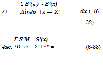
and Keune (1955) for its physical perspicuity. It is seen that the kernel in the integral (6-27) for small r is approximately

Solutions for Subsonic and Supersonic Flows Подпись: 1 S'(Xl) - S'(x) dx i, (6-32) X) AirJo |x — X! | 4ж. Ґ S'M - S'(x) 10 x - Х!І dXl■ (6-33)

In the second term of (6-29) we may use the approximation (6-28) because the numerator tends to zero for xx —> x (the error actually turns out to be of order r2 In r). Thus, collecting all the terms in (6-29), we find that for small r

The last term gives the effect due to variation of source strength at body stations fairly far away from station x. This form of the integral is par­ticularly convenient when the cross-sectional area distribution is given as a polynomial, since then the integrand will become a polynomial in xx. We may obtain an alternate form by performing an integration by parts in (6-33). This gives

cx

g(x) = ^~lnf — 4~ Jo s"(xi)ln (x — xi) dxx

+ Il-f S"(x0 ln (Xi — x) dxx, (6-34)

where we have assumed that S'(0) = S'(l) = 0, that is, the body has a pointed nose and ends in a point or in a cylindrical portion.

The solution for supersonic flow can be found in the same manner. Using (5-38) we obtain

rx—Br

1 S'(xi) dxx /n nr4

<p = — 7T~ – — – -—:———- _ ’ (6-35)

6ТГ J a /(x — Xl)2 — B2r2

where

В = VM2 – 1.

The upper integration limit follows because each source can only be felt inside its downstream Mach cone; hence the rearmost source that can influence the flow in the point x, r is located at xx = x — Br. Rewriting of (6-35) in a similar manner as (6-30) gives

(6-36)

For the first term we obtain

Подпись: x-Brdx 1

Подпись: = —ln Br + ln [x + /x2 — B2r2 ] Solutions for Subsonic and Supersonic Flows Подпись: (6-37)

уДх — xx)2 — B2r2

In the second integral we may replace the square root by x — xx as before. In addition, the upper integration limit may be replaced by x for

Подпись: , V S’(x) В g{x) = ^ In- Solutions for Subsonic and Supersonic Flows Solutions for Subsonic and Supersonic Flows

That the correct factor 1/27Г (cf. 6-24) was obtained for the first term confirms the constant for the supersonic source solution (5-38) selected by intuitive reasoning. For the supersonic case we thus have

Подпись: g(x) Подпись: S' (ж), в FFln2 Подпись: s. Подпись: S"(xi) In (x — xi) dxi, (6-40)

As with subsonic flow, an alternate form can be obtained by integrating the last term by parts. This yields

where we have assumed that <8′(0) = 0. This form will be used later for the calculation of drag.

Подпись: 47Г Подпись: <S"(xi) In (xi Подпись: x) dxi,

It is interesting to note how g(x) changes from subsonic to supersonic flow, as seen by comparing (6-34) with (6-40). First, /3 is replaced by B. Secondly, the integral

which represents the upstream influence in subsonic flow, changes to

— Jo s"(xi) ln (x — xi) dxb

that is, becomes equal to half the total downstream influence. To under­stand this behavior, consider the disturbance caused by a source in one cross section x as it is felt on the body at other cross sections. The dis­turbance will spread along two wave fronts, one wave moving downstream with a velocity of (approximately) ax + Ux and the other either upstream or downstream with a velocity of aw — Ux, depending on whether the flow is subsonic or supersonic. The effect of fast-moving waves is given by the first integral in (6-34), whereas that of slow-moving waves is given by the second integral. In the supersonic case, the fast and slow waves each contribute half of the integral in (6-40). Because of the small cross­wise dimensions of the body, the curvature of the waves may be neglected in the present approximation. Hence their fronts may be treated as plane, the total effect being given by a function of x only.

image86

Fig. 6-і. Pressures on the forward portion on a body of revolution. [Adapted from Drougge (1959). Courtesy of Aeronautical Research Institute of Sweden.]

A comparison of calculated and measured pressure distributions given by Drougge (1959) is shown in Fig. 6-1. The excellent agreement despite the fairly large thickness ratio (r = £) demonstrates the higher accuracy of slender-body theory than thin-airfoil theory. In the former theory the error term is of order e4 (or, rather, e4 In e), whereas in the latter it is of order e2. In assessing the accuracy of slender-body theory for practical cases, however, one must remember that the body considered in Fig. 6-1 is very smooth, with small second derivative of the cross-sectional area distribution, and should therefore be ideally suited for the theory.

The weak Mach number dependence of In |1 — Л/21 as compared to |1 — A/2|~1/2 in the thin-airfoil case, with the associated weaker singu­larity at M = 1, is significant. It indicates that the linearized slender-body theory generally holds closer to M = 1 than does the thin-airfoil theory for the same thickness ratio, i. e., the true transonic region should be much

smaller. For the body in Fig. 6-1, the linearized theory gives accurate pressure distributions for M < 0.90 and M > 1.10. In the transonic region the slow-moving waves will have time to interact and accumulate on the body, thus creating nonlinear effects that cannot be treated with the present linearized theory. The transonic case will be further discussed in Chapter 12.

Implicit in the derivation of the theory was the assumption that S’ is continuous everywhere, as is also evident from the results which show that <p becomes logarithmically singular at discontinuities of S’ and the pressure thus singular as the inverse of the distance. However, the slender-body theory may be considered as the correct “outer” solution away from the discontinuity with a separate “inner” solution required in its immediate neighborhood. Such a theory has in effect been developed by Lighthill (1948).

Conservation Laws for a Barotropic Fluid. in a Conservative Body Force Field

Conservation Laws for a Barotropic Fluid. in a Conservative Body Force Field Подпись: S2 — Подпись: dp P. Подпись: (1-11)

Under the limitations of the present section, it is easily seen that the law of conservation of momentum, (1-3), can be written

The term “barotropic ” implies a unique pressure-density relation through­out the entire flow field; adiabatic-reversible or isentropic flow is the most important special case. As we shall see, (1-11) can often be integrated to yield a useful relation among the quantities pressure, velocity, density, etc., that holds throughout the entire flow.

Подпись: where Подпись: DT Dt Подпись: (, dp c P Подпись: c T ds’ Подпись: (1-12)

Another consequence of barotropy is a simplification of Kelvin’s theorem of the rate of change of circulation around a path C always composed of the same set of fluid particles. As shown in elementary textbooks, it is a consequence of the equations of motion for inviscid fluid in a conservative body force field that

image4(1-13)

is the circulation or closed line integral of the tangential component of the velocity vector. Under the present limitations, we see that the middle member of (1-12) is the integral of a single-valued perfect differential and therefore must vanish. Hence we have the result DT/Dt = 0 for all
such fluid paths, which means that the circulation is preserved. In par­ticular, if the circulation around a path is initially zero, it will always remain so. The same result holds in a constant-density fluid where the quantity p in the denominator can be taken outside, leaving once more a perfect differential; this is true regardless of what assumptions are made about the thermodynamic behavior of the fluid.