Category AERODYNAMICS

SUPERPOSITION OF SOURCES AND FREE STREAM: RANKINE’S OVAL

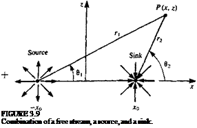
As a first example for using the principle of superposition, consider the two-dimensional flow resulting from superimposing a source with a strength a at x = —Xq, a sink with a strength —a at x = +x0- both on the * axis, and a free stream flow with speed Um in the x direction (Fig. 3.9). The velocity potential

Подпись: FIGURE 3.9 Combination of a free stream, a source, and a sink.

for this case will be

Ф(дс, z) = Ikx + ^ In (rO – ~ In (r2) (3.87)

where і"і = V(* + x0)2 + z2, and r2 = VC* — x0)* + z2. The stream function can be obtained by adding the stream functions of the individual elements:

Ф(х, z) = U„z + ^ 0! – ^ в2 (3.88)

where

Z Z

в і = tan-1——– and 02 = tan-1——————-

X +x0 x – x0

Substituting rt, r2, ви and в2 into the velocity potential and the stream function yields

Подпись: 4>(x, z)= U„z + —tan 1 — tan 2 л x +x0 2л Подпись: x-x0 Подпись: (3.88a)

Ф(х, z) = Uojc + ~~In V(x + x())2 + z2-In V(x – x0)2 + z2 (3.87a) 2n 2n

The velocity field due to this potential is obtained by differentiating either the velocity potential or the stream function:

ЭФ ri, о x+xo a x-x„

и = — = t4 + —- ——- -5—– — ——— rx— 5 (3.89)

Эх 2л (x + x0)2 + z2 2л (x – x0)2 + z2

ЭФ о z о z

Подпись: dz 2л (x + x0)2 + z2 2л (x - x0)2 + z2 Because of the symmetry about the x axis the stagnation points are locatedW = — = — -—:———ї ~ :———— гт“—5 (3.90)

image93 SUPERPOSITION OF SOURCES AND FREE STREAM: RANKINE’S OVAL

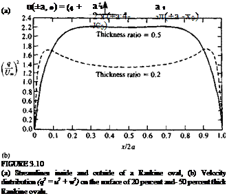
along the x axis, at points further out than the location of the source and sink, say at x = ±a (Fig. 3.10a). The w component of the velocity at these points (and along the x axis) is automatically zero, too. The distance a is then found by setting the и component of the velocity to zero

and a is

image95(3.91)

Consider the stagnation streamline (which passes through the stagnation

4′(*,z) = l/„z+-3tan l—TT-Tl^n l~_x

ZJT X T Xq £7% X Xq

Подпись: a Подпись: = 0 Подпись: (3.92)

points). The value of Ф for the stagnation streamline can be found by observing the value of Eq. (3.88) on the left-side stagnation point (where 6y = 62 = я, and z = 0). This results in V = 0, which can be shown to be the same for the right-side stagnation point as well (where = 62 = 0). The equation for the stagnation streamline is therefore

The streamlines of this flow, including the stagnation streamline, are sketched in Fig. 3.10a and the resulting velocity distribution in Fig. 3.10b. Note that the stagnation streamline includes a closed oval shape (called Rankine’s oval after W. J. M. Rankine, a Scottish engineer who lived in the nineteenth century) and the x axis (excluding the segment between x = ±a). This flow (source and sink) can therefore be considered to model the flow past an oval of length 2a. (For this application, the streamlines inside the oval have no physical significance.) The flow past a family of such ovals can be derived by varying the parameters a and x0 or a, and by plotting the corresponding streamlines.

PRINCIPLE OF SUPERPOSITION

If Ф1; Ф2,…, Ф„ are solutions of the Laplace equation (Eq. (3.1)), which is linear, then

(З. Щ

k=1

is also a solution for that equation in that region. Here cb c2, . . . , c„ are arbitrary constants and therefore

VM> = І ck У2Ф* = О

*=i

This is a very important property of the Laplace equation, since after obtaining some of the elementary solutions, satisfying a set of given boundary conditions can be reduced to an algebraic search for the right linear combination of these solutions (to satisfy the boundary conditions).

BASIC SOLUTION: VORTEX

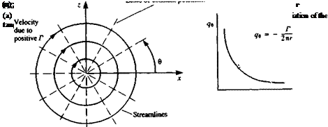
The general solution to Laplace’s equation as stated in Eqs. (3.13) and (3.17) consists of source and doublet distributions only. But as indicated in Section 3.6, other solutions to Laplace’s equation are possible and based on the vortex flow of Section 2.10 we shall formulate the velocity potential and its derivatives for a point vortex (the three-dimensional velocity field is then given by the Biot-Savart law of Section 2.11). Therefore, it is desired to establish a singularity element with only a tangential velocity component, as shown in Fig. 3.8a, whose magnitude will decay in a manner similar to the decay of the radial velocity component of a two-dimensional source (e. g., will vary with 1 /r):

qr = 0

qg = qe(r, в)

Substituting these velocity components into the continuity equation (Eq.

(1.35) ) results in qe being a function of r only

Яв = Яв(г)

image86,image87,image88

For irrotational flow, substitute these relations into the vorticity expression to get

By integrating with respect to r, we get

rqe = const. = A

image89 Подпись: •rdd = —2лA

So the magnitude of the velocity varies with 1/r similarly to the radial velocity component of a source. The value of the constant A can be calculated by using the definition of the circulation Г as in Eq. (2.36):

Подпись: qr = 0 Г Чв~~г яг

Note that positive Г is defined according to the right-hand rule (positive clockwise), therefore, in the x-z plane as in Fig. 3.8 the line integral must be taken in the direction opposite to that of increasing 0. The constant A is then

and the velocity field is

(3.77)

(3.78)

As expected, the tangential velocity component decays at a rate of 1/r as shown in Fig. 3.86. The velocity potential for a vortex element at the origin can be obtained by integration of Eqs. (3.77) and (3.78):

Ф= q0rde + C = -^-e + C (3.79)

і 2 л

where C is an arbitrary constant that can be set to zero. Equation (3.79) indicates too that the velocity potential of a vortex is multivalued and depends on the number of revolutions around the vortex point. So when integrating around a vortex we do find vorticity concentrated at a zero area point, but with finite circulation (see Sections 2.9 and 2.10). However, if integrating q*dl around any closed curve in the field (not surrounding the vortex) the value of the integral will be zero (as shown at the end of Section 2.10 and in Fig. 2.11a). Thus, the vortex is a solution to the Laplace equation and results in an irrotational flow, excluding the vortex point itself.

Equations (3.77) to (3.79) in cartesian coordinates for a vortex located at (xo, 2o) are

Подпись: -iПодпись: (3.80) (3.81) Z-Zp

x —x0

Г z-Zp

2n(z-Zo)2 + (x-x0)2

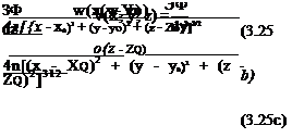
_T_____ x-x0

Подпись: (3.82)2я (z — Zq)2 + (x — x0)2

To derive the stream function for the two-dimensional vortex located at the origin, in the x-z (or r-d) plane, consider the velocity components in terms of the stream function derivatives

Подпись: (3.83) (3.84) __3W______

dr 2яг

law

Integrating Eqs. (3.83) and (3.84) and setting the constant of integration to zero yields

image91(3.85)

and the streamlines where W = const, are shown schematically in Fig. 3.8a.

TWO-DIMENSIONAL VERSION OF THE BASIC SOLUTIONS

Source. We have seen in the three-dimensional case that a source element will have a radial velocity component only. Thus, in the two-dimensional r-6 coordinate system the tangential velocity component qe = 0. Requiring that the flow be irrotational yields

[Iі{rq’y- Те И=теш~°

and therefore the velocity component in the /–direction is a function of r only (qr = qr(r)). Also, the remaining radial velocity component must satisfy the continuity equation (Eq. (1.35)):

dr r r dr

This indicates that rqT = const. = о 12л where a is the area flow rate passing through a circle of radius r, and the resulting velocity components for a source element at the origin are

Подпись:Подпись: (3.58)_ ЭФ _ a ^r Эг 2лг

ЭФ

где

By integrating these equations the velocity potential is found,

Ф = In r + C (3.59)

and the constant C can be set to zero, as in the source potential used in Eq.

(3.19) .

The strength of the source is then a, which represents the flux introduced by the source. This can be shown by observing the flux across a circle with a radius R. The velocity at that location, according to Eq. (3.57), is o/2nR, and the flux is

a

qr2nR = —— 2 nR = a 2nR

So the velocity, as in the three-dimensional case, is in the radial direction only (Fig. 3.3e) and decays with a rate of 1/r. At r = 0, the velocity is infinite and this singular point must be excluded from the region of the solution.

In cartesian coordinates the corresponding equations for a source located

Ф(дс, z) = — in V(* – x0)2 + (z – Zof

TWO-DIMENSIONAL VERSION OF THE BASIC SOLUTIONS Подпись: о x — x0 2л (x - x0)2 + (z - z0)2 O Z-Zp 2л (x - x0)2 + (z - z0)2 Подпись: (3.60) (3.61) (3.62)

at (x0, z0) are

Подпись: Яв = Подпись: dr Подпись: (3.63)

In the two-dimensional case, the velocity components can be found as the derivatives of the stream function for a source at the origin. Recalling these formulas (Eqs. (2.80a, b)) and comparing with the velocity components results in

Подпись: (3.64)1ЭУ о ^r г дв 2лг

Integrating Eqs. (3.63) and (3.64) and setting the constant of integration to zero yields

Ф = (3.65)

The streamlines (Eq. (3.65)) and the perpendicular constant potential lines (Eq. (3.59)) for the two-dimensional source resemble those for the three – dimensional case and are shown schematically in Fig. 3.3a.

Doublet. The two-dimensional doublet (Fig. 3.7) can be obtained by letting a point source and a point sink approach each other, such that their strength multiplied by their separation distance becomes the constant ц (as in Section

3.5) . Because of the logarithmic dependence of the source potential, Eq.

(3.32) becomes

Подпись: FIGURE 3.7 Streamlines and equipotential lines due to a two-dimensional doublet at the origin, pointing in the x direction.
image85
image84

ф(г).-|^ (3.66)

which can be derived directly by using Eq. (3.33), and by replacing the source strength by fi,

Э a

Ф(г) = – —— lnr an 2 7t

(3.67)

As an example, selecting n in the x direction yields

ц = (ju, 0)

and Eq. (3.66) for a doublet at the origin becomes

^ и cos в ф(г, в) = ~

2л r

(3.68)

The velocity field due to this element can be obtained by differentiating the velocity potential:

ЗФ /л cos в dr 2 лг2

(3.69)

1 ЗФ (i sin в г дв 2лг2

(3.70)

In cartesian coordinates for such a doublet at the point (jc0, z0)>

t – jU X~X°

{X, Z) 2л (x – x0)2 + (z – z0)2

(3.71)

and the velocity components are

F (x – x0f – (z – z0f U 2л [(x – x0)2 +(z – z0)2]2

(3.72)

H 2(x – x0)(z – z„)

Ш s — – — —

2^r [(* — x0)2 + (z — Zo)2]2

(3.73)

To derive the stream function for this doublet element, located at the origin, write the above velocity components in terms of the stream function derivatives:

ЭФ fi sin в dr 2 лг2

(3.74)

1 dW fi cos в r dd 2лг2

(3.75)

Integrating Eqs. (3.74) and (3.75) and setting the constant of integration to zero yields (see streamlines in Fig. 3.7):

(i sin в

Note that a similar doublet element where ц = (0, ц) can be derived by using Eq. (3.66) (or (3.67)),

BASIC SOLUTION: POLYNOMIALS

Since Laplace’s equation is a second order differential equation, a linear function of position will be a solution, too:

<P = Ax + By + Cz (3.49)

The velocity components due to such a potential are

ЭФ ЗФ ЗФ

и = — = A = Ux v = — = B = V„ w = — = (3.50)

dx dy dz

Подпись: and in general BASIC SOLUTION: POLYNOMIALS Подпись: (3.51) (3.52)

where Цо, V„, and Wx are constant velocity components in the x, y, and z directions. Hence, the velocity potential due a constant free-stream flow in the x direction is

Along the same lines, additional polynomial solutions can be sought and as an example let’s consider the second-order polynomial with A, B, and C being constants:

Ф = Ax2 + By2 + Cz2 (3.53)

To satisfy the continuity equation,

У2Ф = A + B + C = 0

There are a large combination of constants that will satisfy this condition. However, one combination where one of the constants is equal to zero (e. g., В = 0) describes an interesting flow condition. Consequently

A = —C

and by substituting this result into Eq. (3.53) the velocity potential becomes

Ф = А(х2 —z2) (3.54)

The velocity components for this two-dimensional flow in the x-z plane are

и = 2Ax и = 0 w = -2Az (3.55)

To visualize this flow, the streamline equation (1.6a) is needed:

dx _dz и w

and substituting the velocity components yields

dx _ dz 2Ax 2Az

Integration by separation of variables results in

xy – const. = D (3.56)

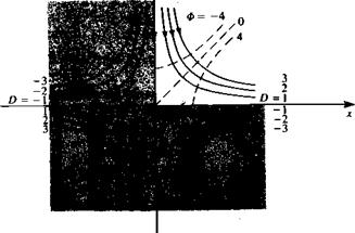
The streamlines for different constant values of D = 1, 2, 3 • • • are plotted in Fig. 3.6 and, for example, if only the first quadrant of the x-z plane is considered, then the potential describes the flow around a corner. If the upper half of the x-z plane is considered then this flow describes a stagnation flow against a wall. Note that when x = z = 0, the velocity components и = >v = 0 vanish too—which means that a stagnation point is present at the origin, and the coordinate axes x and z are also the stagnation streamline.

image83

FIGURE 3.6

Streamlines defined by xz = constant. Note that each quadrant describes a flow in a comer.

BASIC SOLUTION: POINT DOUBLET

The second basic solution, presented in Eq. (3.13), is the doublet

<p = -£-n-v(T) (3.29)

4 я rf

BASIC SOLUTION: POINT DOUBLET

A closer observation reveals that

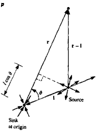
for elements of unit strength. This suggests that the doublet element can be developed from the source element. Consider a point sink at the origin and a point source at 1, as shown in Fig. 3.4. The potential at a point P, due to these two elements, is

Подпись: Ф =• =-—(———– —) (3.30)

4л |r| |r —1|/ V }

Now, bringing the source and the sink together by letting l—*0, o—>°° such that la-* fi, and ц is finite, the potential becomes

(7—»oo

As the distance l approaches zero,

|r| |r I| * r2

and the difference in length between |r| and |r -1| becomes

(|r —1| – |r|)—p/cos i?

Подпись: p FIGURE 3.4

The influence of a point source and sink at point P.

The angle # is between the unit vector Є/ pointing in the sink-to-source direction (doublet axis) and the vector r, as shown in the figure. Defining a vector doublet strength ц that points in this direction ц = ц e, can further simplify this equation:

Подпись:

Подпись: and the potential becomes
Подпись: fi cos# 4 n r2
Подпись: (3.31)

pr

4яг3

Note that this doublet element is identical to the second term appearing in the general equation of the potential (Eq. (3.13), or Eq. (3.29)) if e, is in the n direction, thus

$doubie. 4лтз «w( 4лт) dn Ф^игсе (3.33)

For example, for a doublet at the origin, the doublet strength vector (fi, 0, 0) aligned with the x axis (e, = ex and § = в), the potential in spherical coordinates is

^„ ч fi cos 0

Ф(г, в, q>) = —(3.34)

Furthermore, in cartesian coordinates, the arbitrary orientation of ц can be expressed in terms of three generic unit doublet elements whose axes are aligned with the coordinate directions:

(fi, 0, 0) (0, fi, 0) (0, 0, fi)

image80 Подпись: JLJL 4 л dn Подпись: (3.35)
image81

The different elements can be derived for each of these three doublets by using Eq. (3.32) or by differentiating the corresponding term in Eq. (3.29) using Э/дп as the derivative in the direction of the three axes. The velocity potential due to such doublet elements, located at (jc0) y0, A)), is:

Taking 9/dn in the x, y, and z directions yields

Подпись: (3.36)/ d/9x i

ф<*’»г)I »£)

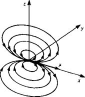
Equation (3.34) shows that the doublet element does not have a radial symmetry and it has a directional property. Therefore, in cartesian coordinates three elements are defined each pointing in the x, y, or z directions (see, for example, the element pointing in the x direction in Fig. 3.5). After performing

FIGURE 3.5.

image82Sketch of the streamlines due to a doublet pointing in the x direction (e. g., like a small jet engine blowing in the ц = (ft, 0, 0) direction).

the differentiation in Eq. (3.36) in the x direction the velocity potential is

Ф(х, У, z) = – у-(x – x0)[(x – *o)2 + (У – Уо)2 + (z – z0)2] 3/2 (3- 37)

4 л

The result of the differentiation in the у direction is

ф(*, y, z) = -y-(y-Уо)[(* – Xo)2 + (у – Уо)2 + (z – z0)2]-3/2 (3.38)

4 Jt

and the result in the z direction is

Ф(*. У, z) = –£-(z – Zo)l(-z – -«о)2 + (У ~ Уо)2 + (z – Zo)T3/2 (3.39)

BASIC SOLUTION: POINT DOUBLET

The velocity field, due to an x-directional point doublet {ft, 0, 0) is illustrated in Fig. 3.5. The velocity components due to such an element at the origin are easily described in spherical coordinates:

ЭФ fi cos в

4r~ dr ~ 2 лг3

(3.40)

1 ЭФ n sin в Чв~гдв~ 4лг3

(3.41)

1 Зф n qv- . a з – 0 v r sin в 9<p

(3.42)

The velocity components in cartesian coordinates for this doublet at (x0, Уо» Zo) can be obtained by differentiating the velocity potential in Eq. (3.37):

|Ц(*о, Уо, z0)(x – x0) dl

ф(х, у, z) I ^ + ^ _ Л)2 + (2 _ Zq)2]3/2

<b(r v r = __L [ f*(x°>У°> Zo)(x-x0)dS

4л Js [(x – x0)2 + (y – y0)2 + (z ~ Zoff2

Ф(x у z) = ~— f ^Xo’ y°’ Zo)(-X ~Xo) dV

4 Jt Jy

BASIC SOLUTION: POINT DOUBLET BASIC SOLUTION: POINT DOUBLET

Again, this basic point element can be integrated over a line /, a surface 5 or a volume V to create the corresponding singularity elements that can be used, for example, to construct panel elements. Consequently, these elements [e. g., for (/і, 0, 0)] can be established by the following integrals:

BASIC SOLUTION: POINT SOURCE

BASIC SOLUTION: POINT SOURCE Подпись: (3.19)

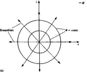
One of the two basic solutions presented in Eq. (3.13) is the source/sink. The potential of such a point source element (Fig. 3.3a), placed at the origin of a spherical coordinate system, is

The velocity due to this element is obtained by using V in spherical coordinates

from Eq. (1.39). This will result in a velocity field with a radial component only,

Подпись:Подпись: (3.21)____ о _/l a ег _ о t

^ 4 л r/ 4 лг2 4л r3

and, in spherical coordinates,

(‘b’qe’= (‘"dr1 °* °)= (w’0* °)

image76,image77

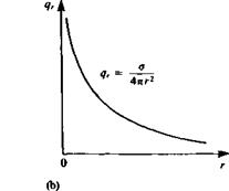
So the velocity in the radial direction decays with the rate of 1/r2 and is singular at r = 0, as shown in Fig. 3.36. Consider a source element of strength a located at the origin (Fig. 3.3a). The volumetric flow rate through a spherical surface of radius r is

image78FIGURE 33

(a) Streamlines and equipotential lines due to source element at the origin, as viewed in the x-z plane, (b) Radial variation of the radial velocity component in­duced by a point source.

where 4лг2 is the surface area of the sphere. The positive a, then, is the volumetric rate at which fluid is introduced at the source, whereas a negative a is the rate at which flow is going into the sink. Note that this introduction of fluid at the source violates the conservation of mass, therefore, this point must be excluded from the region of solution.

If the point element is located at a point r0 and not at the origin, then the corresponding potential and velocity will be

Подпись: (3.22) (3.23) 4it |r – r0|

О Г-Го

4л |г – г„|3

The cartesian form of this equation, when the element is located at (x0, y0, A>)>

Ф^’У’ Z^ 4лІ(х – x0)2 + (y – y0)2 + (z – zof ^3’24^

The velocity components of this source element are

Подпись: ЭФ u(x, y, z) = —= Подпись:a(x – x0)

BASIC SOLUTION: POINT SOURCE

Эх 4л[{х – Xq)2 + (у – уо) + (z – zb)2]3

This basic point element can be integrated over a line l, a surface S or a volume V to create corresponding singularity elements that can be used, for example, to construct panel elements. Consequently, these elements can be established by the following integrals:

Подпись:Подпись:<4*0, УО, Zq) dl

V(* – x0) + (у – Уо) + (z – Zof

<4*o, Уо, Zq) dS

V(* – *0)2 + (y – Уо)2 + (z – z0)2
a(x0, y0, Zq) dV

V(x – Xq)2 + (y – y0)2 + (z – Zq)2

Note that a in Eqs. (3.26), (3.27), and (3.28) represents the source strength per unit length, area, and volume, respectively. The velocity components induced by these distributions can be obtained by differentiating the cor­responding potentials:

SUMMARY: METHODOLOGY OF SOLUTION

In view of Eq. (3.13) ((3.17) in two dimensions), it is possible to establish a fairly general approach to the solution of incompressible potential flow problems. The most important observation is that/the solution of У2Ф = 0 can be obtained by distributing elementary solutions (sources and doublets) on the problem boundaries (SB, Sw). These elementary solutions automatically fulfill the boundary condition of Eq. (3.3) by having velocity fields that decay as
r—»oo. However, at the point where r = 0, the velocity becomes singular, and therefore the basic elements are called singular solutions.

The general solution requires the integration of these basic solutions over any surface S containing these singularity elements because each element will have an effect on the whole fluid field.

The solution of a fluid dynamic problem is now reduced to finding the appropriate singularity element distribution over some known boundaries, so that the boundary condition (Eq. (3.2)) will be fulfilled. The main advantage of this formulation is its straightforward applicability to numerical methods. When the potential is specified on the problem boundaries then this type of mathematical problem is called the Dirichlet problem (Kellogg,13 p. 286) and is frequently used in many numerical solutions (panel methods).

A more direct approach to the solution, from the physical point of view, is to specify the, zero normal flow boundary condition (Eq. (3.2)) on the solid boundaries. This problem is known as the Neumann problem (Kellogg,13 p. 286) and in order to evaluate the velocity field the potential is differentiated

w – c 1 *0 л+s L/ 0]e + ,3’18)

Again, the derivative d/dn for the doublet indicates the orientation of the element as will be shown in Section 3.5. Substituting this equation into the boundary condition of Eq. (3.2) can serve as the basis of finding the unknown singularity distribution. (This can be done analytically or numerically.)

For a given set of boundary conditions, the above solution technique is not unique, and many problems can be solved by using only one type of singularity element or any linear combination of the two singularities. Therefore, in many situations additional considerations are required (e. g., the method that will be presented in the next chapter to define the flow near sharp trailing edges of wings). Also, in a particular solution a mixed use of the above boundary conditions is possible for various regions in the flowfield (e. g., Neumann condition on one boundary and Dirichlet on another).

Prior to attempting to apply this methodology to the solution of particular problems, the features of the elementary solutions are analyzed in the next sections.

THE GENERAL SOLUTION, BASED ON GREEN’S IDENTITY

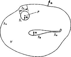
The mathematical problem of the previous section is described schematically by Fig. 3.1. Laplace’s equation for the velocity potential must be solved for an arbitrary body with boundary SB enclosed in a volume V, with the outer boundary S„. The boundary conditions in Eqs. (3.2) and (3.3) apply to SB and Soo, respectively. The normal n is defined such that it always points outside the region of interest V. Now, the vector appearing in the divergence theorem (e. g., q in Eq. (1.20)) is replaced by the vector Ф^Ф2 — Фг^Фъ where Ф! and Ф2 are two scalar functions of position. This results in

(Ф^Ф2 – Ф2УФі). n dS = (Ф^2Ф2 – Ф^ФО dV (3.4)

image70

Подпись: FIGURE 3.1image71Nomenclature used to define the potential flow problem.

Подпись: S — SB + Sw + S„
Подпись: Also, let us set

This equation is one of Green’s identities (Kellogg,13 p. 215). Here the surface integral is taken over all the boundaries S, including a wake model Sw (which might model a surface across which a discontinuity in the velocity potential or the velocity may occur).

Подпись:Фі = — and Ф2 = Ф r

where Ф is the potential of the flow of interest in V, and r is the distance from a point P(x, y, z), as shown in the figure. As we shall see later, Ф, is the potential of a source (or sink) and is unbounded (1 /r—»») as P is approached and r-* 0. In the case where the point P is outside of V both Ф! and Ф2 satisfy Laplace’s equation and Eq. (3.4) becomes

I (lv<P-<l>vlyndS = 0 … (3.6)

Of particular interest is the case when the point P is inside the region. The point P must now be excluded from the region of integration and it is surrounded by a small sphere of radius e. Outside of the sphere and in the remaining region V the potential Ф! satisfies Laplace’s equation [V2(l/r) = 0]. Similarly У2Ф2 = 0 and Eq. (3.4) becomes

f (-V<P-<PV-)-ndS = 0 (3.6a)

To evaluate the integral over the sphere, introduce a spherical coordinate system at P and since the vector n points inside the small sphere, n = —er, n • УФ = — дФ/Эг and V(l/r) = —(l/r2)er. Equation (3.6a) now becomes

On the sphere surrounding P, J dS = Але2 (where r = e), and as e—>0 (and assuming that the potential and its derivatives are well-behaved functions and therefore do not vary much in the small sphere) the first term in the first integral vanishes, while the second term yields

-1 (?) dS = ~4лф(р)

«^sphere € ‘* ‘

Equation (3.66) then becomes

Ф(Р)=Т~ f (-УФ-ФУ-)-ndS (3.7)

4л Js r r)

This formula gives the value of Ф(Р) at any point in the flow, within the region V, in terms of the values of Ф and дФ/дп on the boundaries S.

If, for example, the point P lies on the boundary SB then in order to exclude the point from V, the integration is carried out only around the surrounding hemisphere (submerged in V) with radius e and Eq. (3.7) becomes

Ф(Р) = ^| 0уФ-ФУ^-ш<И (3.7a)

Now consider a situation when the flow of interest occurs inside the boundary of SB and the resulting “internal potential” is Ф,. For this flow the point P (which is in the region V) is exterior to SB and applying Eq. (3.6) yields

0 = – i-f (іуФ,-Ф, У-)-«^ "" (3.7b)

4л }Sb r г/

Here, n points outward from SB. A form of Eq. (3.7) that includes the influence of the inner potential, as well, is obtained by adding Eqs (3.7) and (3.7b) (note that the minus sign is a result of the opposite direction of n for

Ф,):

Ф(Р) = f Г – У(Ф — Ф,-) — (Ф — Ф<) V -1 • n dS 4я Jsgl/’ rJ

+ -— f (- 7Ф — Ф V -) • n dS (3.8)

4л JSw+Sw r rJ

The contribution of the integral in Eq. (3.8) (when S„ is considered to be far from SB) can be defined as ФХ(Р).

Ф.(Р) = —f (^Ф-ФУ-)-пгі5 (3.9)

4л Js. r r!

This potential, usually, depends on the selection of the coordinate system and, for example, in an inertial system where the body moves through an otherwise stationary fluid Ф® can be selected as a constant in the region. Also, the wake surface is assumed to be thin, such that ЭФ/дп is continuous across it (which means that no fluid-dynamic loads will be supported by the wake). With these assumptions Eq. (3.8) becomes

ф(Р) = —f ГІу(Ф-ФІ)-(Ф-Фі)У-1-п</5–^-f Фп • V – dS + Ф»(Р) v 4л JSb Lr r J 4л JSw r

(3.10)

As was stated before, Eq. (3.7) (or Eq. (3.10)) provides the value of Ф(Р) in terms of Ф and дФ/дп on the boundaries. Therefore, the problem is reduced to determining the value of these quantities on the boundaries. For example, consider a segment of the boundary SB as shown in Fig. 3.2; then the difference between the external and internal potentials can be defined as

Подпись: (3.11)– jU = Ф – Ф,

FIGURE 3.2

The velocity potential near a solid boundary Sb.

and the difference between the normal derivative of the external and internal potentials as

Подпись: (3.12)

Подпись: ЭФ дп
Подпись: Ф

ЭФ ЭФ, dn dn

image73 Подпись: -fin image74

These elements are called doublet (/i) and source (o) and the minus sign is a result of the normal vector n pointing into SB. The properties of these elementary solutions will be investigated in the following sections. With the definitions of Eqs. (3.11) and (3.12), Eq. (3.10) can be rewritten as

(3.13)

The vector n here is the local normal to the surface, which points in the doublet direction (as will be shown in Section 3.5). It is convenient to replace n • V by d/dn in this equation, and it becomes

image75 Подпись: dn r.

(3.13a)

Note that both source and doublet solutions decay as r-*°° and automatically fulfill the boundary condition of Eq. (3.3).

In order to find the velocity potential in the region V, the strength of the distribution of doublets and sources on the surface must be determined. Also, Eq. (3.13) does not specify a unique combination of sources and doublets for a particular problem and a choice must be made in this matter (usually based on the physics of the problem).

THE GENERAL SOLUTION, BASED ON GREEN’S IDENTITY

It is possible to require that

Ф, = Ф on SB

and in this case the doublet term on SB vanishes and the problem will be modeled by a source distribution on the boundary.

In the two-dimensional case the source potential is «I»! = In r as will be shown in Section 3.7, and the two functions of Eq. (3.5) become

Фі = In r and Ф2 = Ф (3.14)

Also at the point P, the integration is around a circle with radius є and Eq.

(3.66) becomes

— f (in r ^ — Ф -) dS + f (In г УФ – ФУ In r) • n dS = 0 (3.15)

•’circle € ‘ v/" Г / J5

The circumference of the small circle around P is now 2лє (compared to 4;re2 in the three-dimensional case) and Eq. (3.7) in two dimensions is

Ф(Р) = -2- f (In г УФ – Ф V In r) • n dS (3.16)

2 Jt J5

If the point P lies on the boundary SB, then the integration is around a semicircle with radius є and Eq. (3.16) becomes

Ф(Р)=– f (lnrV<P-<PVlnr)-ndS (3.16a)

Л Js

whereas if P is inside SB the two-dimensional version of Eq. (3.76) is

0 = — t— f (In г УФ, — Ф, V In r) • n dS (3.166)

2 л Js

With the definition of the far field potential Ф» and the unit elements fi and a being unchanged, Eq. (3.13a) for the two-dimensional case becomes

ф(/,) ■ h l. [°1to ■r ^~ ■ці(to ■r)] ■- h 1 -‘‘inV"r)i^ф-(п (3-‘‘7)

Note that d/dn is the orientation of the doublet as will be illustrated in Section

3.7 and that the wake model Sw in the steady, two-dimensional lifting case is needed to represent a discontinuity in the potential Ф.
EQUATIONS

In the previous two chapters the fundamental fluid dynamic equations were formulated and the conditions leading to the simplified inviscid, incompres­sible, and irrotational flow problem were discussed. In this chapter, the basic methodology for obtaining the elementary solutions to this potential flow problem will be developed. Because of the linear nature of the potential flow problem, the differential equation does not have to be solved individually for flowfields having different geometry at their boundaries. Instead, the elemen­tary solutions will be distributed in a manner that will satisfy each individual set of geometrical boundary conditions.

This approach, of distributing elementary solutions with unknown strength, allows a more systematic methodology for resolving the flowfield in both of the cases of “classical” and numerical methods.

3.1 STATEMENT OF THE POTENTIAL FLOW PROBLEM

For most engineering applications the problem requires a solution in a fluid domain V that usually contains a solid body with additional boundaries that may define an outer flow boundary (e. g., a wing in a wind tunnel), as shown in Fig. 3.1. If the flow in the fluid region is considered to be incompressible and

irrotational then the continuity equation reduces to

Подпись: (3.1)У2Ф = 0

For a submerged body in the fluid, the velocity component normal to the body’s surface and to other solid boundaries must be zero, and in a body fixed coordinate system:

Подпись: (3.2)УФ•n = 0

Here n is a vector normal to the body’s surface, and УФ is measured in a frame of reference that is attached to the body. Also, the disturbance created by the motion should decay far (r—»°°) from the body

Подпись: (3.3)lim (УФ – v) = 0

where r = (x, y, z) and v is the relative velocity between the undisturbed fluid in V and the body (or the velocity at infinity seen by an observer moving with the body).