Category AERODYNAMICS

STEPS TOWARD CONSTRUCTING A NUMERICAL SOLUTION

When establishing a potential-flow numerical solution a sequence similar to the following is recommended.

Selection of singularity element. The first and one of the most important decisions is the type of singularity element or elements that will be used. This includes the selection of source, doublet, or vortex representation and the method of discretizing these distributions (zero-, first-, second-order, etc.). Also, all of the questions raised in the previous section need to be answered before the actual formulation of the solution can be constructed. Once these decisions have been made an influence routine needs to be established, similar to the model of Eq. (9.22). This influence computation is a direct function of the element geometry and the resulting output of such a routine is the velocity components and the potential (Am, Ді/, Aw, ДФ) induced by the element. In general, the implementation of Eq. (9.22) represents the core of most numerical solutions. Therefore, in the next chapter some of the more frequently used singularity elements will be formulated.

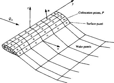
Discretization of geometry (and grid generation). Once the basic solution element is selected, the geometry of the problem has to be subdivided (or discretized), such that it will consist of those basic solution elements. In this grid-generating process, the elements’ corner points and collocation points are defined. The collocation points are points where the boundary conditions, such as the zero normal flow to a solid surface, will be enforced. Figure 9.14m shows how the cambered thin airfoil at an angle of attack can be discretized by using the lumped-vortex element. In this case the camberline is divided into five panels and the location of the collocation points and of the vortex points are shown in the figure. Similarly, the subdivision of a three-dimensional body into planar surface elements (the collocation points are not shown but they are at the center of the panel and may be slightly under the surface) is shown in Fig. 9.14 b.

It is very important to realize that the grid does have an effect on the solution. Typically, a good grid selection will converge to a certain solution when the density is increased (within reason). Also a good grid selection usually will require some preliminary understanding of the problem’s fluid dynamics, as will be shown in some of the forthcoming examples.
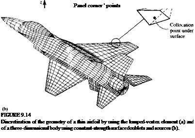
image350
Influence coefficients. In this phase, for each of the elements, an algebraic equation (based on the boundary condition) is derived at the collocation point. To generate the coefficients in an automatic manner, a unit singularity strength is assumed and the element influence routine is called at each of the collocation points (by a DO loop).

Establish RHS. The right-hand side of the matrix equation is the known portion of the free-stream velocity or the potential and requires mainly the computation of geometric quantities (e. g., —Q„a).

Solve linear set of equations. The coefficients and the RHS of the algebraic equations were obtained in the previous steps and now the equations are solved by standard matrix techniques. Here it is assumed that the reader is familiar with such numerical solvers, which can be found in text books (e. g.,
Подпись: Computation of RHS (right-hand side) 9 Solution of matrix 9 Pressures, velocity components, loads, etc.

Подпись: Definition of geometry T Computation of influence coefficients

FIGURE 9.15

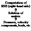
Typical flow chart for the numerical solution of the surface singularity distribution problem.

Ref. 9.4 or as the solvers appearing in the student computer programs of Appendix D).

Secondary computations: pressures, loads, velocity, etc. The solution of the matrix equation results in the singularity strengths and the velocity field and any secondary information can be computed now. The pressures will be computed by the Bernoulli equation, and the loads and aerodynamic coefficients by adding up the contributions of the elements. A typical flow chart for such a computer program is shown in Fig. 9.15 where the sequence of computations is close to the above-described methodology.

In the following example, the essence of the above steps will be clarified.

PRELIMINARY CONSIDERATIONS, PRIOR TO ESTABLISHING NUMERICAL SOLUTIONS

Prior to establishing a numerical solution, some of the options need to be considered:

Type of singularity that will be used

The options usually include sources, doublets and vortices or any combination of the above.

Type of boundary conditions

Velocity or velocity-potential formulation may be used and the corresponding Neumann, Dirichlet, or a combination of such boundary conditions must be selected.

Wake models

How and where the Kutta condition will be specified. Also the shape of the wake is controlled by Eq. (9.18a) and can be set by:

1. Programmer specified shape based on intuition or on flow visualizations.

2. Wake relaxation (where the wake points are moved with the local induced velocity, e. g. in Ref. 9.2).

3. Time stepping (where the wake shape is developed by moving the wing from an initial stand-still position, as will be presented in Chapter 13).

Method of discretizing surface and singularity distributions;

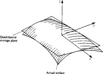
1. Discretization of geometry. The placing of a simple panel element on an arbitrary three-dimensional configuration is rather difficult. Figure 9.11 describes such a curved surface element with a local coordinate system x, y, z. The shape of the surface can be described as z = f(x, y), but for simplicity it is usually approximated by a piecewise polynomial approxima­tion. For example, if a first-order polynomial is used then the average surface can be described by

z = a0 + b1x + b2y

and for a second-order polynomial approximation

z = a0 + biX + b2y + CjX2 + c2xy + c3y2

PRELIMINARY CONSIDERATIONS, PRIOR TO ESTABLISHING NUMERICAL SOLUTIONS

image347

FIGURE 9.11

Nonplanar surface element and its quadrilateral approximation.


PRELIMINARY CONSIDERATIONS, PRIOR TO ESTABLISHING NUMERICAL SOLUTIONS

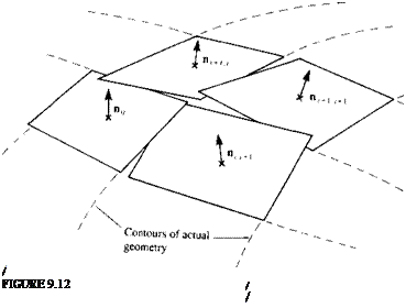
Possible difficulty m representing a three-dimensional surface by an array of quadrilateral surface elements.


image349

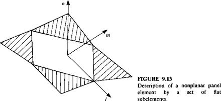
and so on (where the coefficients a, b, c are constants). Figure 9.11 shows the result of approximating a curved surface element by a first-order plane, while Fig. 9.12 shows the possible consequence of representing a three – dimensional curved surface by such quadrilateral elements. This repre­sentation of the geometry may result in difficulties in specifying the boundary conditions, since the “leakage” between the panels can weaken the satisfaction of the zero flow through the boundaries requirement. One possible solution is shown in Fig. 9.13 where the surface is described by five flat subelements (as in the PANAIR code9 3).

2. Discretization of singularity distribution. The strength of the surface distribution of the singularity elements can be represented, too, in terms of a piecewise polynomial approximation. For example, if the doublet distribution on the element of Fig. 9.11 is constant such that

Iu = a0 = const.

then this is a zero-order approximation of ц. Similarly a first-order (or linear) approximation is

H=a0 + blx + b2y

and a second-order (or parabolic) polynomial approximation is

ц = а0 + Ьгх + b2y + сгх2 + c2xy + c3y2

(Here the coefficients a, b, c, .. . are constants, too, and of course are different from the coefficients of the surface approximation).

Considerations of numerical efficiency

It is clear from the brief discussion on discretization that the computation of the influence coefficients (e. g., Eq. (9.21)) is elaborate. Many methods divide such calculations into near and far field where the far-field calculation treats the element as a point singularity (and not as a surface distribution). Typically, the near field is assumed if the distance to a point P is less than 2.5-5 times the larger diagonal of the panel. Because of the 1/r characteristics of the singularity elements, when r—> 0 the value of 1/r—therefore, when the point P is too close to the panel (or to a vortex line) cut-off distances are usually applied. (Only the aerodynamic aspects of the numerics are discussed here; other important aspects, e. g., the matrix solver efficiency, are not.)

AERODYNAMIC LOADS

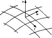
Once Eq. (9.25) is solved the unknown singularity values are obtained (цк in this example). The velocity components are evaluated now in terms of the panel local coordinates (l, m,n) shown in Fig. 9.10. The two tangential perturbation velocity components are

Подпись: (9.26)_ dfi dfi

q,~~3l =

where the differentiation is done numerically using the values on the neighbor

FIGURE 9.10

image346Panel local coordinate system for evaluating the tangen­tial velocity components.

panels. The normal component of the velocity is obtained from the source (in this example):

qn = – o (9.27)

The total velocity in the local (/, m, n) direction of panel к is

Q* = (Qoo,, Qocm, <2=0* + (qh qm, q„)k (9.28)

Подпись: сл = і Подпись: Ql Qi Подпись: (9.29)

and of course the normal velocity component on a solid boundary is zero. The pressure coefficient can now be computed for each panel using Eq. (4.53):

AERODYNAMIC LOADS

The contribution of this element to the nondimensional fluid dynamic loads is normal to the panel surface and is

AC*

Подпись: CPk AS/c S
Подпись: (9.30)

where S is a reference area. In terms of the pressure coefficient the panel contribution to the fluid dynamic load becomes

The individual contributions of the panel elements now can be summed up to compute the desired aerodynamic forces and moments.

REDUCTION OF THE PROBLEM TO A SET OF LINEAR ALGEBRAIC EQUATIONS

At this point it is assumed that the problem is unique and that a combination of source/doublet distributions has been selected along with a wake model and the Kutta condition. For the following example Ф* = Ф» along with Eq. (9.12) for the source strength will be used and a constant-strength rectilinear panel is assumed (this approach is widely used in many panel codes such as in Ref. 9.2). The body (see Fig. 9.7) is now divided into N surface panels, and into Nw wake panels. The boundary condition (either Neumann or Dirichlet) will be specified at each of these elements at a “collocation point” (which for the Dirichlet boundary condition must be specified inside the body where Ф,* = Ф«, e. g., at a point under the center of the panel). In most cases,

image338

FIGURE 9.7

Approximation of the body surface by panel elements.

image339,image340 Подпись: ds

though, the point may be left on the surface without moving it inside the body. By rewriting, for example, the Dirichlet boundary condition for each of the N collocation points, Eq. (9.11) will have the following form:

Подпись:-2 —f

к 1 4ТГ Jbody-panel кГ/

Подпись: 4 я Подпись: (9.21)
image341

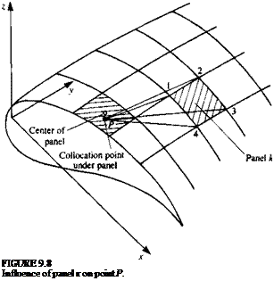
That is for each collocation point P (shown in Fig. 9.7) the summation of the influences of all к body panels and I wake panels is needed. The integration is limited now to each individual panel element, and for a unit singularity element (a or ц) it depends on the panel’s geometry only. The integration can be performed analytically or numerically, prior to this calculation, and, for example, for a constant-strength fi element shown in Fig. 9.8 the influence of panel к (defined by the four corners 1, 2, 3, and 4) at point P is

Подпись:Подпись: -1 4 nimage342and for a constant strength a element

Подпись: FIGURE 9.8 Influence of panel к on point P.

(9.21a)

These integrals are a function of the points 1, 2, 3, 4 and P and an “influence computing routine” can be schematically defined as

(Xp, yP, zP (9.22)

influence . * a a

coefficient W

calculation/ ‘ ‘

Xi, yt, zi

Хг, У2,*2 |ф

x3,y3,z3 I х4,Ул,24 I

Of course, in this case ЛФ/> = Ck. After computing the influence of each panel on each other panel Eq. (9.20) for each point P inside the body becomes

N Nw N

2 Ckfik + 2 С, Ці + X Bkak = 0 for each internal point P (9.23)

*=і /=i *=i

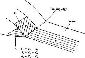
This equation is the numerical equivalent of the boundary condition. If the strengths of the sources are selected according to Eq. (9.12) then the coefficients Bk, which are computed in a manner similar to Eq. (9.22), are known and can be moved to the right-hand side of the equation. Also, by using the Kutta condition, the wake doublets can be expressed in terms of the unknown surface doublets pk. For example, in Fig. 9.9 two of the trailing edge (T. E.) doublets цг, jUj (here r, s, and t are some arbitrary counters) are related to the corresponding wake doublet fi, by Eq. (9.15),

V, = Pr~ Ps

and consequently the influence of the wake element becomes

С, ц, = C,(Hr – Ps)

This algebraic relation can be substituted into the Ck coefficients of the unknown surface doublets such that

A* = Ck if panel is not at T. E.

Ak = Ck ± C, if panel is at T. E.

image344FIGURE 9.9

Relation between trailing edge up­per and lower panel doublet stren­gth and the corresponding wake doublet strength.

where the ± sign depends on whether the panel is at the upper or the lower side of the trailing edge (Fig. 9.9). Consequently, for each collocation point P, a linear algebraic equation containing N unknown singularity variables цк can be derived:

N

2 Akfik = – 2 Bkok (9.24)

*=i *=i

Evaluating Eq. (9.24) at each of the N collocation points (j = 1 -*N) results in N equations with the N unknown цк, in the following form:

image345

all» fl12> a21» a22>

Подпись:°m> aN2> ■ ■ ■ » aNN/ ^/V

Note that for evaluating the influence of the panel on itself {akk, bkk) the integral of the influence coefficients may be singular and its principal value must be evaluated. In this formulation the unknown ц distribution is small (perturbation only) and the numerical solution is believed to be more stable.9 2 The right-hand side of Eq. (9.25) can be computed since the value of ok is known and Eq. (9.25) can be rewritten as

«11 > a2> • • • » N / Pl / RHS,

Vrhs*

Подпись:

Подпись: am> am> Подпись: aNN/ HN/

«21» a22> • • ■ > a2N W P2 I RHSj

where the values of fJ. k can be computed by solving this full-matrix equation.

Also, the relation a = Q„ • n of Eq. (9.12) contains the information on the zero normal flow condition for the thickness problem and this formulation will be singular for surfaces approaching zero thickness.

The derivation of the influence coefficient integrals depends on the shape of the panel element (e. g., planar, curved, etc.), and on the singularity distribution (constant or linearly varying strength, etc.) and some examples will be presented in the following chapters.

PHYSICAL CONSIDERATIONS

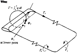
The above mathematical formulation, even after selecting a desirable com­bination of sources and doublets, and after fulfilling the boundary conditions on the surface SB, is not unique. Previous examples showed that for describing the flow over thick bodies without lift the source distribution was sufficient, but for the lifting cases the amount of the circulation was not uniquely defined. Before proceeding further, (and using the information developed in Chapter 8), let us examine the case of a lifting wing, as viewed from a large distance (Fig. 9.2). For simplicity, the bound vortex is represented by a concentrated vortex line with the strength Г (= Г* = Гг). According to the Helmholtz theorems (Section 2.9) a vortex line cannot start in a fluid and following Eq. (4.64)

Подпись:ЗГ, = 5Г, dy dx

which for the simple case of Fig. 9.2 implies that the problem is modeled by one, constant strength, closed vortex line. Also, the amount of the bound circulation is

Г = J q dl

where point 1 lies under and point 2 is above the (very) thin wake. These two arguments clearly demonstrate that for the three-dimensional lifting problem there is a need to model a wake, since the bound vorticity needs to be continued beyond the wing. Also, as shown in Fig. 9.2, in order for the wing to have circulation Г at a spanwise location (see Section 3.14), a discontinuity in the velocity potential near the trailing edge must exist:

Ф2 “ Фі = Г

where Ф] is under and Ф2 is above the wake. Now we are in a position where the additional physical conditions, required for a unique solution, can be

Подпись: Wing FIGURE 9.2

Vorticity system created by a finite wing in steady forward flight.

established in relation to a wake model. This model has to specify two additional conditions:

1. To set the wake strength at the trailing edge

2. To set its shape and location.

WAKE STRENGTH. The simplest solution to this problem is to apply the two-dimensional Kutta condition along the three-dimensional trailing edge (as shown in Fig. 9.3) such that

Уте. = 0 (914)

Since, for example, in the two-dimensional case d[i(x)/dx = – y(x) (as in Section 3.14) the above condition can be rewritten for the trailing edge line, such that ju is constant in the wake (nw) and equals the value at the trailing edge (mt. e.)

Mt. e. ~ = const.

Hu~ dw = 0 (9.15)

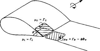
where (ifj and nL are the corresponding upper and lower surface doublet strengths at the trailing edge, as shown in Fig. 9.3. As an example, the specification of this Kutta condition in terms of constant-strength doublet elements (or vortex rings) is shown in Fig. 9.4 (here for convenience a positive doublet points into the wing). At the wing’s trailing edge, the trailing segment of the upper doublet will have a strength of – Гу, the leading vortex segment of the lower surface (which is now inverted) will be +TL and the leading segment of the wake vortex is +rw. Thus, the strength of the wake panel in terms of the local circulation Г is again

—Гу + TL + Г w = 0

or exactly as in Eq. (9.15),

rw = ry-rL (9.16)

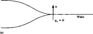
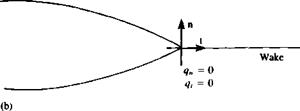
In certain situations also the shape of the trailing edge is important. For example, Fig. 9.5a shows a situation where the flow leaves the trailing edge

image333

FIGURE 93

Implementation of the Kutta condition when using surface doublet distribution.

Positive direction of Г

image334

FIGURE 9.4

Implementation of the Kutta condition when using vortex ring elements.

smoothly and parallel to the cusped trailing edge. In such situations this point is not necessarily a stagnation point and if the velocity formulation is used then only the qn= 0 condition can be used. In the case that the trailing edge has a finite angle (Fig. 9.5b), then in order to have a continuous velocity at this point the condition q, = 0 can also be used.

WAKE SHAPE. In two dimensions, the trailing vortex segment of the wake is not present and it is sufficient to specify the location of the trailing edge where the Kutta condition is met. In three dimensions, the wake influence is more

image335

image336

FIGURE 9.5

Possible conditions that can be applied at (a) cusp and (b) finite angle trailing edges.

dominant and its geometry clearly affects the solution. To distinguish between the models for bound circulation (which generate the lift) and the circulation shed into the wake, it is logical to assume that the wake should not produce lift—since it is not a solid surface. As an example, let’s recall the formulation for the force AF generated by a vortex sheet with vorticity y. The Kutta – Joukowski theorem for lift (Section 3.11) states that

AF = pq X у (9.17)

For a three-dimensional case AF = 0 only if the local flow is parallel to у (we

assume у =£ 0). So the condition for the wake geometry is

qXyw=0 (9.18)

or the vorticity vector is parallel to the local velocity vector

Ywllq (9.18a)

An equivalent representation of the wake by a thin doublet sheet is obtained

by noting that yw = — (this will be demonstrated in Chapter 10). If no force is produced by this lifting surface then Eq. (9.18) becomes

Я x — 0 (9.19)

So the condition for the wake panels, in terms of doublets, is

jUw = const. (9.19a)

and the boundaries of these elements (which are really the vortex lines) should be parallel to the local streamlines, as in Eq. (9.18a). This condition (Eq. (9.18a)) is difficult to satisfy exactly since the wake location is not known in advance. In most cases it is sufficient to assume that the wake leaves the trailing edge at a median angle 6T E /2, as shown in Figs. 9.3 and 9.4, whereas

image337

FIGURE 9.6

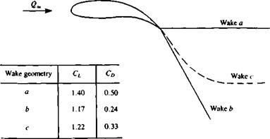
Effect of prescribed wake geometry on the aerodynamics of an Ж = 1.5 wing.

for portions of the wake far from the trailing edge additional effort is required in order to satisfy the condition of Eq. (9.18).

As an example of the dependence of the solution on the wake initial geometry, the results for a cambered rectangular wing of aspect ratio 1.5 are shown in Fig. 9.6. The solution was obtained by a first-order panel method (VSAERO9 2) with 600 panels per semispan and the corresponding lift and drag coefficents are tabulated in the inset to the figure (incidentally, case c is the closest to experimental results).

Dirichlet Boundary Condition

Подпись: ф ?(x,y,z) = j-( 4-ТГ •'body+wake &ЇІ Г/ image329 Подпись: (9.9)

In this case, the perturbation potential Ф has to be specified everywhere on SB. Equation (9.2a) does this exactly, and by distributing the singularity elements on the surface, and placing the point (x, y, z) inside the surface SB the inner potential Ф* in terms of the surface singularity distributions is obtained:

Again, these integrals are singular when r-*0 and near this point their principal value must be evaluated. The zero flow normal to the surface boundary condition (Eq. (9.4)) is defined now using Eq. (9.8). Therefore, the
condition У(Ф + Ф„) • n = 0, in terms of the velocity potential, becomes

Ф,* = (Ф + ФД = const.

or

image330dS + Ф* = const.

(9.10)

Equation (9.10) is the basis for methods utilizing the indirect boundary conditions. However, even at this stage, there are many differences between the various methods of solution, related to setting the value of the inner potential Ф* (in addition to the differences in the source/doublet combina­tions). For example, by setting Ф(* = (Ф + Ф„), = 0, Eq. (9.10) can be solved on the surface SB but the resulting singularity distribution will include Ф» and the strength will be large.

Other values for the inner potential can be specified too (not necessarily constant) and when the inner potential is set to Ф,* = (Ф + Ф„), = Ф* (which is equivalent to specifying Eq. (9.10) for the perturbation only in a “ground-fixed frame” where Ф„ = 0) then Eq. (9.10) reduces to a simpler form:

Подпись: г I "f® 4JT Jbody+wake Г/ Подпись: dS = 0image331(9.11)

To justify the above, consider the Neumann boundary condition (Eq. (9.4)) ЭФ*/Эп = 0, which is equivalent to ЭФ/Эп = — n • Q„. Recall that the value for the discontinuity in the normal derivative of the velocity potential as given by Eq. (3.12) is

9Ф* ЭФ* ЭФ ЭФ,

° дп дп дп дп

and since Ф, = 0 then also ЭФ,/дп = 0 on SB. Consequently, for Eq. (9.11) to be valid, the source strength is required to be

<r = n-Qoo (912)

where n points into the body as in Fig. 9.1.

To define this problem uniquely, the wake doublet distribution should be known or related to the unknown doublets on SB (Kutta condition). To proceed with the solution, SB is divided into discrete elements and at each of these elements Eq. (9.10) (or Eq. (9.11)) is evaluated. This results in a set of algebraic equations for the unknown /x distribution. Note that when evaluating the integrals at a point P on the element (r—»0) then Ф(Р) = Т/х/2 (see Section 3.14).

In this formulation, when Eq. (9.12) is used, the zero normal flow boundary condition information is contained in the source terms and for very thin surfaces the integral may be ill-conditioned and will cause numerical instabilities.

Neumann Boundary Condition

In this case it is required that ЭФ*/дп will be specified on the solid boundary SB, e. g.:

У(Ф + Ф„) • n = 0 (9.4)

where Ф is the perturbation potential consisting of the two integral terms in Eq. (9.2a). From this point and on, for convenience, the velocity potential will be split such that Ф„ is the free-stream velocity potential (Eq. 9.3) relative to the origin of the coordinates attached to the surface SB. The second boundary condition (at the distant, outer boundaries of the flow) requires that the flow disturbance, due to the body’s motion through the fluid, should diminish far from the body,

lim УФ = 0 (9.5)

where r = (x, y,z). This condition is automatically met by all the singular solutions considered here. To satisfy the boundary condition in Eq. (9.4)

directly, we use the velocity field due to the singularity distribution of Eq.

УФ*(х, у, z) = – f

4л Jb

dS + V*!)»

(9.6)

(9.2)

image327
image328

:

If the singularity distribution strengths о and p are known, then Eq. (9.6) describes the velocity field everywhere (of course, special treatment is needed when the velocity is evaluated on the surface SB). Substitution of Eq. (9.6) into the boundary condition in Eq. (9.4) results in:

fr~f ‘lVfT'(")ldS-r" f oV(“)d5+V$4’n=0 (9-7>

14я Jbody+wake 1дпгП 4Л )ъойу W J

This equation is the basis for many numerical solutions and should hold for every point on the surface SB. For example, a certain number of points (called collocation points) can be selected on the surface SB. The boundary condition of Eq. (9.7) is then specified at each of these points in terms of the unknown singularities at all the collocation points. This approach reduces the integral equation (Eq. (9.7)) to a set of algebraic equations. As noted in Chapter 3, the solution at this point is not unique, and the combination of sources and doublets must be specified.

Note that if for an enclosed boundary (e. g., SB) ЭФ*/Эп =0, as required by the boundary condition in Eq. (9.4), then the potential inside the body (without internal singularities) will not change (Lamb,9 1 p. 41):

Подпись: (9.8)Ф* = const.

which constant could be selected also as zero. This observation is important since it allows us to specify the boundary condition (Eq. (9.4)) in terms of the potential inside SB, which is the Dirichlet problem (or Dirichlet boundary condition).

THE BOUNDARY CONDITIONS

The boundary condition for Eq. (9.1) can directly specify a zero normal velocity component ЭФ*/дп = 0 on the surface SB, in which case this “direct” formulation is called the Neumann problem. It is possible to specify Ф* on the boundary, so that indirectly the zero normal flow condition will be met, and this “indirect” formulation is called the Dirichlet problem. Of course, a combination of the above boundary conditions is possible, too, and this is called a mixed boundary condition problem.

An additional approach would be to search for a singularity distribution that creates enclosed streamlines, equivalent to the geometry of the surface SB. This method is useful in two dimensions, where the stream function Ф is well defined (and hence the streamlines Ф = const, can be easily derived as in Sections 3.10, 3.11), but for complex, three-dimensional geometries the implementation of this method is difficult and will not be dealt with here.

BASIC FORMULATION

Consider a body with known boundaries SB, submerged in a potential flow, as shown in Fig. 9.1. The flow of interest is in the outer region V where the incompressible, irrotational continuity equation, in the body’s frame of reference, in terms of the total potential Ф* is

V2<l>* = 0 (9.1)

Following Green’s identity, as presented in Section 3.2, the general solution to Eq. (9.1) can be constructed by a sum of source о and doublet p distributions placed on the boundary SB (Eq. (3.13)):

Ф*(х, у, Z) = – [o0) – pn • V0)] dS + Фоо (9.2)

Here the vector n points in the direction of the potential jump p which is normal to SB and positive outside of V (Fig. 9.1), and Ф„ is the free-stream potential:

Фоо = І/».* + К, у + WLz (9.3)

This formulation does not uniquely describe a solution since a large number of source and doublet distributions will satisfy a given set of boundary conditions (as discussed in Chapter 3). Therefore, an arbitrary choice has to be made in order to select the desirable combination of such singularity elements. It is clear from the previous examples (in Chapters 4-8), that for simulating the effect of thickness, source elements can be used, whereas for lifting problems, antisymmetric terms such as the doublet (or vortex) can be used. To uniquely define the solution of this problem, first the boundary conditions of zero flow normal to the surface must be applied. In the general case of three-dimensional flows, specifying the boundary conditions will not immedi­ately yield a unique solution because of two problems. First, an arbitrary decision has to be made in regard to the “right” combination of source and doublet distributions. Secondly, some physical considerations need to be introduced in order to fix the amount of circulation around the surface SB.

v

image326

FIGURE 9.1

Potential flow over a closed body.

These considerations deal mainly with the modeling of the wakes and fixing the wake shedding lines and their initial orientation and geometry. (This is the three-dimensional equivalent of a two-dimensional Kutta condition.) However, based on the previous examples, it is likely that the wake will be modeled by thin doublet or vortex sheets (Fig. 9.1) and therefore Eq. (9.2) can be rewritten as

Ф *(x, y,z)=—j ;

‘тЛ •’body+wake

METHODS

In the previous chapters the solution to the potential flow problem was obtained by analytical techniques. These techniques (except in Chapter 6) were applicable only after some major geometrical simplifications in the boundary conditions were made. In most of these cases the geometry was approximated by flat, zero-thickness surfaces and for additional simplicity the boundary conditions were transferred, too, to these simplified surfaces (e. g., at z = 0).

The application of numerical techniques allows the treatment of more realistic geometries, and the fulfillment of the boundary conditions on the actual surface. In this chapter the methodology of some numerical solutions will be examined and applied to various problems. The methods presented here are based on the surface distribution of singularity elements, which is a logical extension of the analytical methods presented in the earlier chapters. Since the solution is now reduced to finding the strength of the singularity elements distributed on the body’s surface this approach seems to be more economical, from the computational point of view, than methods that solve for the flowfield in the whole fluid volume (e. g., finite-difference methods). Of course this comparison holds for inviscid incompressible flows only, whereas numerical methods such as finite-difference methods were basically developed to solve the more complex flowfields where compressibility and viscous effects are not negligible.