Category Airplane Stability and Control, Second Edition

High-Altitude Stall Buffet

A Mach number-altitude operating envelope is a useful concept for jet airplanes. With Mach number plotted as the abscissa, the right-hand boundary gives the maximum operating Mach number at each altitude. This is ordinarily established by buffet for com­mercial airplanes. Military airplanes have higher design load factors, and structural strength or controllability ordinarily sets the right-hand maximum operating Mach number. When buffet, structural, or controllability limits do not apply, maximum Mach number is estab­lished by the highest speed attainable in dives from maximum altitude.

The left-hand boundary gives the minimum operating Mach number at each altitude. Ordinary stall generally defines the low-altitude minimum operating Mach number. Air­frame buffeting due to flow separation can define the minimum operating Mach number at high altitude, since that Mach number can be high enough for compressibility-induced flow separation. There is a significant stability and control involvement when stall buffet is responsible for the minimum operating Mach number at high altitude. This is because when a high-altitude stall buffet boundary is breached when an airplane is upset by turbulence, the pilot may use the controls too vigorously to recover.

This seems to have happened in 1992 with a McDonnell Douglas MD-11 airliner cruising at a Mach number of 0.70 at an altitude of33,000 feet. The airplane was upset by turbulence. In recovering from the upset, it slowed to a Mach number of 0.50 while making four successive penetrations of the stall buffet boundary.

Control Friction and Apparent Spiral Instability

A spirally stable airplane, when disturbed in bank angle from wings-level flight, will return on its own to wings-level flight, although on a different heading than it had before the disturbance. On the other hand, the bank angle of a spirally unstable airplane will increase without limit after an initial disturbance. A spirally unstable airplane’s bank angle must be corrected continuously to maintain wings-level flight. However, for the usual case

Control Friction and Apparent Spiral Instability

Figure 15.4 Time history of a precision instrument approach in light turbulence, using ILS, for an unspecified general-aviation airplane. This model has low Dutch roll damping and other stability and control deficiencies. The pilot uses large stick and rudderpedal forces, but airspeed, heading and path angle variations are excessive. (From Barber, Jones, Sisk, and Haise, NASA TN D-3726, 1966)

of moderate spiral instability, with times to double amplitude of the order of 20 seconds, corrections are made instinctively. Pilots are generally unaware of the instability.

Therefore, it is not surprising that Ralph Upson’s 1942 set of objectives for a safe personal airplane do not include spiral stability. That is, if one were only to make airplanes “as easy to fly as cars are to drive,” spiral stability would not necessarily be an objective. Yet, positive spiral stability has over the years been of interest to personal-airplane designers.

One reason for this is that Federal Aviation Regulations for airplanes operating under Visual Flight Rules (91.205) do not require gyroscopic rate of turn indicators. Without one of these instruments the pilot of an airplane that blunders into clouds has no way of maintaining wings-level flight, unless the airplane happens to be spirally stable. In that case, freeing the controls prevents a “graveyard spiral.” Another reason for spirally stable personal airplanes is to enable a solo pilot to be able to read a map without finding the airplane in a bank upon looking up.

Unfortunately, an inherently spirally stable airplane can appear to be spirally unstable with rudders and ailerons free, as a result of control friction (Campbell, Hunter, Hewes, and Whitten, 1952). To correct this, NACA researchers designed a rather complicated control­centering device to overcome friction without interfering with normal control activity.

A cylindrical barrel encloses two preloaded compression springs and a shaft passing through the barrel. A shoulder on the shaft and corresponding shoulders on the inside of the barrel are at its midlength. A flat circular pickup ring under the end of each spring is forced against both shoulders with a force equal to the spring preload. The shaft cannot move relative to the barrel without moving one of the pickup rings and consequently compressing one of the springs. Campbell’s group installed the preload barrels in both the rudder and the aileron control systems of a Cessna 190. An electric motor provides rudder trim, a jack screw provides aileron trim, and solenoids engage or disengage the preload devices (Figure 15.5).

Without the centering devices, the airplane diverged in the direction of a rudder kick, after a kick and release of all controls. However, the centering devices allowed the Cessna’s inherent spiral stability to take effect. After a rudder kick and release of all controls the airplane returned to wings-level flight, and would continue so indefinitely.

Laplace Transforms, Frequency Response, and Root Locus

One of the minor mysteries in the evolution of the equations of airplane motion is why it was not until 1950 that the Laplace transformation appeared in the open liter­ature as a solution method for the airplane equations of motion. This was in an NACA Technical Note by Dr. G. A. Mokrzycki (1950), who later anglicized his name to G. A. Andrew. Laplace transforms were common among servomechanism engineers and in a few aeronautical offices for at least ten years before that. Laplace transforms provide a much simpler, more organized method for finding time history solutions than the classical operator methods described by B. Melvill Jones (1934) and Robert T. Jones (1936). Laplace trans­forms also provide a formal basis for airplane transfer functions, frequency responses, time vector analysis, and root loci, all used in the synthesis of stability augmentation systems, as described in Chapter 20, “Stability Augmentation.”

Laplace Transforms, Frequency Response, and Root Locus

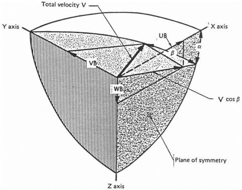
Figure 18.8 Usual angle-of-attack a and sideslip angle в convention, used in the NASA SIM2 flight simulation. X, Y, and Z are body axes. (From Abzug, Northrop paper, 1983)

The Systems Concept

The concept of the airplane’s airframe as only one object in a complete dynamical system is part of the thinking of today’s stability and control engineer, when faced with the need for stability augmentation. Yet, early researchers in airplane stability augmentation did not approach the problem that way (Imlay, 1940). Imlay enlarged on the classical Routh criterion for stability by the use of equivalent airplane stability derivatives. The equivalent derivatives are the basic control-fixed stability derivatives plus the products of control derivatives such as the yawing moment coefficient due to rudder deflection and a gearing ratio. The gearing ratio is an assumed control deflection per unit airplane motion variable. For example, Imlay studied gearings of 0.356 and 1.116 degrees of rudder angle per degree of bank and yaw, respectively.

The point is that the Imlay stability augmentation analysis method deals only with a modified airplane. No other dynamical elements are represented, although the lag effects of the servomechanism that would drive the control surfaces are suggested by a somewhat awkward representation of a simple time lag as the first three terms of the power series for the exponential.

The key mathematical concept that leads to modern augmentation analysis methods is the control element, which is represented graphically by a box having an input and an output. Control element boxes are linked one to another, with the output of one serving as the input to another. Control elements include sensors such as gyros; pneumatic, electric, or hydraulic control actuators; and, of course, the dynamics of the airframe, or control surface angle as an input and motion such as pitch or yaw rate as an output. Summing and differencing junctions act on inputs and outputs as needed, most notably to create an error signal. This is the difference between the commanded and actual system outputs.

Parallel-Line Planform Issues

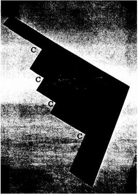
The Northrop B-2 planform strongly distorts from the ideal the additional span load distributions, or the span loadings due to symmetric angle of attack and to rolling. Each planform internal corner, marked “C” in Figure 22.2, produces a sharp local peak in the additional span loading, as do the triangle-shaped wing tips. Premature stalling can be expected in the vicinity of the corners at high angles of attack and at high rolling velocities.

The resultant nonlinearity in the variation of lift with angle of attack at high angles is not in itself a stability and control problem. However, the yawing and rolling moment due to rolling derivatives C„p and Clp, normally negative in sign, become positive at combined high angle-of-attack and rolling velocity values. This problem is countered in the B-2 with an angle-of-attack limiter and with artificial stability increments that are tailored to Cnp and Cip values below the angle-of-attack limits.

Parallel-Line Planform Issues

Figure 22.2 Internal sharp corners, marked “C” on the Northrop B-2 bomber planform. These corners, the result of the stealth parallel-line planform, produce sharp local peaks in the wing’s additional span­load distribution. Premature stalling can be expected in the vicinity of the corners at high angles of attack and rolling velocities.

A second B-2 stability and control issue is the elimination of vertical tails, requiring split ailerons to supply yawing moments in response to pilot and autopilot inputs. The split ailerons act as differential drag devices. The brake drag, and hence yawing moment, is nonlinear with brake opening, requiring further tailoring to produce predictable control moments.

As with all isolated sweptback wings, the B-2 has an inherent low level of positive static directional stability. However, the sweptback hinge lines of the split ailerons result in directional instability whenever the brakes are opened symmetrically at large angles, as an airspeed-control device. The open brakes themselves act as low-aspect-ratio wings, with lift components that produce destabilizing yawing moments when the whole wing is yawed to the airstream. The speed brakes are opened at landing approach airspeeds, putting an additional requirement on the logic that provides artificial directional stability at low airspeeds.

In addition to a very small level of inherent static directional stability, the B-2’s all-wing shape has next to no side force derivative in sideslip, or Cyf>. This creates a flight instrument problem, in that the normal ball-bank component of the turn and slip instrument cannot function as an indication of airplane sideslip. The standard ball-bank component is a lateral accelerometer, calibrated to produce one ball width at a tilt angle of 4.5 degrees, or a lateral acceleration of 0.08 g, in level flight. With virtually no side force developed in sideslip, there is no lateral acceleration to displace the ball. This instrumentation problem is aside from flight dynamics problems that occur with essentially zero Cyf>.

The Northrop B-2 wasthe very first parallel-planform configuration to be built. Engineers who were willing to talk about its development concede that there were some unpleasant stability and control surprises. Radar signature considerations probably rule out allevia­tion of distortions in span load by local wing twist for future applications. Correction for undesirable (positive in sign) values of C„p by artificial stability increments is of course available with sophisticated digital flight control systems, but the amount of correction avail­able is limited for configurations without vertical tails. This is because the rudder power, or ability to generate yawing moments, is small for split aileron controls as compared with conventional vertical tail surfaces.

S. B. Gates in Britain

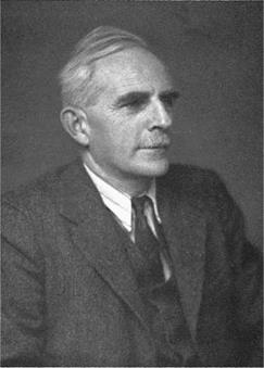
Sidney Barrington (Barry) Gates had a remarkable career as an airplane stability and control expert in Britain, spanning both World Wars. He left Cambridge University in 1914, in his words, “as an illegitimate member of the Public Schools Battalion of the Royal Fusiliers.” Somebody with unusual perception for those days saw that the young mathematician belonged instead in the Royal Aircraft Factory, the predecessor of the Royal Aircraft Establishment or RAE, and he was transferred there.

S. B. Gates in Britain

Figure 3.10 Sidney B. Gates (1893-1973), contributor to understanding of airplane spins; originator of neutral and maneuver points, stick force per g, and many other flying qualities matters. (From Thomas and Kiichemann, Biographical Memoirs of Fellows of the Royal Society, 1974)

Gates remained at the RAE and as a committee member of the Aeronautical Research Council until his retirement in 1972. His total output of papers came to 130, a large pro­portion of which dealt with airplane stability and control. His approach to the subject is described by H. H. B. M. Thomas and D. Kuchemann in a biographical memoir (1974), as follows:

Gates’s life-long quest – how to carve a way through the inevitably harsh and complex mathematics of airplane motion to the shelter of some elegantly simple design criterion based often on some penetrating simplification of the problem.

This approach is seen at its best in his origination of the airplane static and maneuver margins, simple parameters that predict many aspects of longitudinal behavior. He gave the name “aerodynamic center” to the point on the wing chord, approximately 1 /4 chord from the leading edge, where the wing pitching moment is independent of the angle of attack. The wing aerodynamic center concept led to current methods of longitudinal stability analysis, replacing wing center of pressure location.

Gates is also remembered for a long series of studies on airplane spinning, begun with “The Spinning of Aeroplanes” (1926), co-authored with L. W. Bryant. Gates’ other airplane stability and control contributions over his career cover almost the entire field. They include work in parameter estimation, swept wings, VTOL transition, flying qualities requirements, handling characteristics below minimum drag speed, transonic effects, control surface dis­tortion, control friction, spring tabs, lateral control, landing flap effects, and automatic control.

Together with Morien Morgan, in 1942 Gatesmade a two-month tour of the United States, “carrying a whole sackload of RAE reports on the handling characteristics of fighters and bombers.” The pair met with the main U. S. aerodynamics researchers and designers at the time, including Hartley Soule, Gus Crowley, Floyd Thompson, Eastman Jacobs, Robert Gilruth, Hugh Dryden, Courtland Perkins, Walter Diehl, Jack Northrop, Edgar Schmued, W. Bailey Oswald, George Schairer, Kelly Johnson, Theodore von Karman, and Clark Millikan. As Morgan comments, the scope and scale of the 1942 “dash around America” showed what a towering reputation Gates had worldwide.

Trailing-Edge Angle and Beveled Controls

The included angle of upper and lower surfaces at the trailing edge, or trailing- edge angle, has a major effect on control surface aerodynamic hinge moment. This was not realized by practicing stability and control engineers until well into the World War II era. For example, a large trailing-edge angle is now known to be responsible for a puzzling rudder snaking oscillation experienced in 1937 with the Douglas DC-2 airplane. Quoting from an internal Douglas Company document of July 12, 1937 (The Museum of Flying, Santa Monica, California), by L. Eugene Root:

The first DC-2s had a very undesirable characteristic in that, even in smooth air, they would develop a directional oscillation. In rough air this characteristic was worse, and air sickness was a common complaint. …It was noticed, by watching the rudder in flight, that during the hunting the rudder moved back and forth keeping time with the oscillations of the airplane.

It is common knowledge that the control surfaces were laid out along airfoil lines. Because of this fact, the rearward portion of the vertical surface, or the rudder, had curved sides. It was thought that these curved sides were causing the trouble because of separation of the air from the surface of the rudder before reaching the trailing edge. In other words, there was a region in which the rudder could move and not hit “solid” air, thus causing the movement from side to side. The curvature was increased towards the trailing edge of the rudder in such a way as to reduce the supposedly “dead” area. . . . The change that

we made to the rudder was definitely in the wrong direction, for the airplane oscillated severely…. After trying several combinations on both elevators and rudder, we finally tried a rudder with straight sides instead of those which would normally result from the use of airfoil sections for the vertical surfaces. We were relieved when the oscillations disappeared entirely upon the use of this type of rudder.

The Douglas group had stumbled on the solution to the oscillation or snaking problem, reduction of the rudder floating tendency through reduction of the trailing-edge angle. Flat­sided control surfaces have reduced trailing-edge angles compared with control surfaces that fill out the airfoil contour. We now understand the role of the control surface trailing – edge angle on hinge moments. The wing’s boundary layer is thinned on the control surface’s windward side, or the wing surface from which the control protrudes. Conversely, the wing’s boundary layer thickens on the control surface’s leeward side, where the control surface has moved away from the flow. Otherwise stated, for small downward control surface angles or positive wing angles of attack the wing’s boundary layer is thinned on the control surface bottom and thickened on the control’s upper surface.

The effect of this differential boundary layer action for down-control angles or positive wing angles of attack is to cause the flow to adhere more closely to the lower control surface side than to the upper side. In following the lower surface contour the flow curves toward the trailing edge. This curve creates local suction, just as an upward-deflected tab would do. On the other hand, the relatively thickened upper surface boundary layer causes the flow to ignore the upper surface curvature. The absence of a flow curve around the upper surface completes the analogy to the effect of an upward-deflected tab. The technical jargon for this effect is that large control surface trailing-edge angles create positive values of the derivatives Cha and Chs, the floating and restoring derivatives, respectively.

The dynamic mechanism for unstable lateral-directional oscillations with a free rudder became known on both sides of the Atlantic a little after the Douglas DC-2 experience. Unstable yaw oscillations were calculated in Britain for a rudder that floated into the wind (Bryant and Gandy, 1939). This was confirmed in two NACA studies (Jones and Cohen, 1941; Greenberg and Sternfield, 1943). The aerodynamic connection between trailing-edge angle and control surface hinge moment, including the floating tendency, completed the story (Jones and Ames, 1942).

Following the success of the flat-sided rudder in correcting yaw snaking oscillations on the Douglas DC-2, flat-sided control surfaces became standard design practice on Douglas airplanes. William H. Cook credits George S. Schairer with introducing flat-sided control surfaces at Boeing, where they were used first on the B-17E and B-29 airplanes. Trailing – edge angles of fabric-covered control surfaces vary in flight with the pressure differential across the fabric (Mathews, 1944). A Douglas C-74 transport was lost in 1946 when elevator fabric bulging between ribs increased the trailing-edge angle, causing pitch oscillations that broke off the wing tips. C-74 elevators were metal-covered after that.

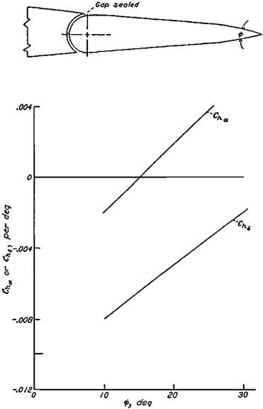
Understanding of the role of the trailing-edge angle in aerodynamic hinge moments opened the way for its use as another method of control force management. Beveled control surfaces, in which the trailing-edge angle is made arbitrarily large, is such an application (Figure 5.8). Beveled control surfaces, a British invention of World War II vintage, work like balancing tabs for small control surface angles.

The beveled-edge control works quite well for moderate bevel angles. As applied to the North American P-51 Mustang, beveled ailerons almost doubled the available rate of roll at high airspeeds, where high control forces limit the available amount of aileron deflection.

Trailing-Edge Angle and Beveled Controls

Figure 5.8 Typical hinge moment parametervariation with bevel angle ф for a beveled control surface. (From Phillips, NACA Rept. 927, 1948)

But large bevel angles, around 30 degrees, acted too well at high Mach numbers, causing overbalance and unacceptable limit cycle oscillations (Figure 5.9). Beveled controls have survived into recent times, used for example on the ailerons of the Grumman/Gulfstream AA-5 Tiger and on some Mooney airplanes.

Nonelectronic Stability Augmentation

Really ingenious nonelectronic stability augmentation systems came out of the jet’s awkward age, as designers tried to have artificial damping without the heavy, costly, and, above all, unreliable electronics of the period. A mechanical yaw damper, invented by Roland J. White and installed on early Boeing B-52 Stratofortresses, is a good example of the genre.

Imagine a rudder tab that is free to rotate on low friction bearings. Instead of being connected to an electric actuator, or to cables leading to the cockpit, the free tab is driven by

Nonelectronic Stability Augmentation

Figure 7.1 Boeing B-52 rudder control linkages. R. J. White’s magnetically phased bobweight yaw damper operates the stability tab. (From B-52 Training Manual, 1956)

inertia forces acting on a small bobweight located ahead of the hinge line (Figure 7.1). Tab position is further modified dynamically by an eddy current damper, providing damping hinge moments proportional to tab rotational velocity.

As the airplane goes through a typical lateral or Dutch roll oscillation, the vertical tail assembly swings from side to side, accelerating the tab bobweight. Without the eddy current damper it is clear that the tab will take up deflections in phase with the lateral accelera­tion at the vertical tail. However, ideally, tab positions should be phased with respect to yawing velocity in such a way as to drive the rudder in opposition. This is the classic yaw damping action, right rudder in opposition to left yawing velocity. The function of the eddy current damper is to “tune” tab deflections to create exactly that phasing. In 1952, a similar approach was taken by M. J. Abzug and Hans C. Vetter of the A3D Skywarrior design team at Douglas Aircraft, to provide nonelectronic yaw damping for that airplane. The design method was cut and try on the analog computer, to find the proper combina­tion of bobweight mass and damper size that would phase the tab, creating effective yaw damping.

The obvious practical problem with the B-52 and A3D yaw dampers is one that is faced with any purely mechanical system, as compared with a modern electromechanical control system. In the mechanical system, the result or output depends critically on the condition of each component. If the free tab’s bearings deteriorate over time or are invaded by grit, or if the eddy current damper’s effectiveness is changed, tab phasing will be thrown off.

In the extreme case, tab action could actually add to the airplane’s lateral oscillation, instead of damping it.

In a July 1994 letter Roland White describes such a situation that actually occurred on a B-52, as follows:

A rudder tail shake on a test airplane caused the magnetic damper to lose its damping. A serious accident would have occurred if the bobweight did not jam due to a mechanical failure. After that I found when going to work the next day your friends will ask if you still work here.

A modern, electromechanical yaw damper drives the rudder in opposition to the measured rate of yaw. It does so by comparing the current rudder position with the desired value and continuing to exert torque on the rudder until that value is reached, overriding mechanical obstacles such as sticky bearings or even losses in performance of the motor that drives the rudder.

The practical shortcomings of purely mechanical yaw damping were not unknown to the Boeing and Douglas design staffs. When a chance appeared to get a yaw damper function electronically, that option was taken instead. In the case of the B-52, the spring-tab – controlled rudders were replaced by powered rudders, allowing Boeing to use the electro­mechanical yaw damper design developed successfully for the B-47.

In the Douglas case, electromechanical yaw damping was installed using components of the airplane’s well-proved Sperry A-12 automatic pilot. The Sperry Gyroscope Company’s DC-3 “dogship” proved the concept in test flights at the Sperry plant in Long Island, New York. Signals from the outer, or yaw, gimbal of the A-12’s free directional gyro were elec­tronically differentiated through a lead network and sent to the rudder servo. Differentiated yaw angle is of course yaw rate.

This worked well when the system was transferred to the A3D and flown routinely at Edwards Air Force Base. Then one day a test pilot bringing an A3D back for landing dove at the runway and pulled up into a chandelle, a natural thing to do for a high-spirited test pilot with an airplane he likes. The A3D, with yaw damper on, responded by applying bottom rudder during the nearly vertical bank, diving the ship back toward the ground.

The pilot regained control and an investigation started at once. The A-12 and yaw damper function were found to be in perfect order. The culprit turned out to be what had been called for years “gimbal error.” The A-12 directional gyro is a conventional two-gimbal free gyro, with yaw measured on the outer gimbal. The rotor, spinning in the inner gimbal, is slaved to magnetic north and the inner gimbal itself is erected to gravity by a bubble level system. The angle between the outer gimbal and the instrument’s case is true yaw or heading angle as long as the outer and inner gimbals are at right angles to each other. This holds only for zero bank angle. At the sharp bank angles of the chandelle, or in any steep turn, the yaw reading picks up errors that depend on the heading angle (Figure 7.2).

During turns, differentiation with respect to time of the erroneous yaw angle exagger­ates the ordinary gimbal errors. The A3D experience proves dramatically that one cannot in general differentiate free gyro signals to produce damping signals for stability augmen­tation, at least for airplanes that maneuver radically. After the all-mechanical and free-gyro A3D yaw damper designs were proved faulty the airplane was finally fitted with what is now the standard design, a single-degree-of-freedom yaw rate gyro driving the rudder servo.

A rather more successful nonelectronic stability augmentation system was developed at the Naval Weapons Center, China Lake, for the AIM-9 Sidewinder missile. The Sidewinder

Nonelectronic Stability Augmentation

Figure 7.2 Gimbal angles of the outer gimbal of the Sperry A-12 directional gyro, as a function of bank and yaw angles. The outer gimbal rate fluctuates strongly in turns at steep bank angles. Differentiating outer gimbal angle to obtain yaw rate caused a near-crash of a Douglas A3D-1 Sky Warrior. (From Abzug, Jour. of the Aero. Sciences, July 1956)

derives roll damping from nonelectronic, air-driven flywheels mounted at the tips of the missile’s ailerons, producing gyroscopic torques that drive the ailerons to oppose roll rate. The flywheel torques are evidently high enough to override variations in aileron bearing friction. There seems to have been no application of this all-mechanical damping system to airplanes.

Air-to-Air Missile-Armed Fighters

A price has to be paid for extreme rolling performance in terms of demands on hydraulic system size and flow rate and on structural weight required for strength and stiffness. This led to a new controversy. As in the days of P-40s versus Zeros, high roll rates were important in dogfight gun-versus-gun battles.

But what about fighters that merely fired air-to-air missiles? Sparrow I and Sidewinder air-to-air missiles both went into service in 1956. Clearly, the missiles themselves can do the end-game maneuvering, to veer left and right, climb and dive, following any feints by the airplane being attacked. Penalizing missile-armed fighters so that they could carry out dogfight tactics might be as foolish as it would have been to require Army tank crews to wear cavalry spurs.

The drive to reduce fighter airplane rolling requirements because of the advent of missile­armed fighters was led on the technical side by a former NACA stability and control engineer who had risen to a high administrative level. The then USAF Director of Requirements weighed in with a letter stating flatly that the F-103 would be the last USAF manned fighter airplane.

The need for high levels of fighter airplane rolling performance was argued back and forth at Wright Field and the Naval Air Systems Command until the issue was settled by the Vietnam War of 1964-1973. U. S. fighters went into that conflict armed with both Sparrow and Sidewinder air-to-air missiles. Nevertheless, they found themselves dogfighting with Russian-built fighters. The reason that aerial combat was carried out at dogfighting ranges was that visual target identification and missile lock-before-launch doctrines were found to be needed, to avoid missile firings at friendly targets. Ranges for positive visual identification were so small that engagements quickly became dogfights. High roll rates were once more in favor. Of course, dogfighting capability meant that guns could still be used effectively on missile-carrying fighters.

Ultralight and Human-Powered Airplanes

The category of ultralight airplanes ranges from hang gliders to light versions of general-aviation airplanes. They fill a need for experimenters and for pilots who want to fly inexpensively and with little regulation. Ultralight airplanes evolved as did the early flying machines, by much cut-and-try and flight testing. Although these designs have been useful, indications are that many commercial ultralights are deficient in stability and control.

Human-powered airplanes are extreme ultralights, designed not for practicality but to push the engineering and human limits of aviation. Early efforts at human-powered flight were discouraging because of the poor performance and extreme fragility of the machines that were constructed before the first successful one, the Gossamer Condor.

13.1 Apparent Mass Effects

For very light airplanes, not much heavier than the air in which they fly, apparent mass effects must be considered. These effects were first noticed in 1836 by George Green, who found that pendulum masses in a fluid medium were apparently greater than in a vacuum. The apparent mass effect can be described as follows (Gracey, 1941):

The apparent increase in mass can be attributed to the additional energy required to establish the field of flow about the moving body. Inasmuch as the motion of the body may be defined by considering its mass as equal to the actual mass of the body plus a fictitious mass, the effect of the inertia forces of the fluid may be represented as an apparent additional mass; this additional mass, in turn, may be considered as the product of an imaginary volume and the density of the fluid. The effect of the surrounding fluid has accordingly been called the additional mass effect. The magnitude of this effect depends on the density of the fluid and the size and shape of the body normal to the direction of motion.

The primary motivation for Gracey’s work was to be able to correct airplane and wind – tunnel model moments of inertia measured by suspending the airplanes or models and swinging them aslarge pendulums. To the extent that the NACA wasinvolved with equations of motion for the airships of those days, this would have given Gracey yet another motivation to study apparent mass.

The 1941, the NACA apparent mass tests were made by swinging covered frameworks of various shapes as compound pendulums. The test specimens were swung both in air and in a vacuum tank. It is interesting that Gracey started out with balsa wood shapes, but found that their weights varied with air pressure and humidity. Gracey’s training in this exacting experimental work must have helped him to appear later on as NASA’s expert in airspeed and altitude measurement methods.

Interest in apparent mass effects returned with the advent of the plastic and fiber materials that could be used to build very light airplanes, such as the human-powered Gossamer Condor and the high-altitude, long-duration pilotless airplanes Pathfinder and Helios, all built by Aero Vironment, Inc., of Monrovia, California. Apparent mass effects are important as well for lighter-than-air and for underwater vehicles. Mathematical models of these craft for dynamic stability analysis include apparent mass terms, as a matter of course. In the series expansions for aerodynamic forces and moments originated by G. H. Bryan, apparent mass terms appear as derivatives with respect to linear and angular accelerations.

Lacking the vacuum swinging apparatus of Green and Gracey, one can approximate apparent mass terms in the equations of airplane motion by adding cylindrical air masses to the lifting surfaces, with diameter equal to the surface chord for motions normal to the chord and equal to the surface thickness for motions in the chord plane. This approximation yields the following astonishing results for the Gossamer Condor. The apparent masses in lateral and vertical motions are 21 and 170 percent of the actual airplane mass. The apparent moments of inertia in pitch and roll are 140 and 440 percent of the actual moments of inertia.

In addition to measurements on swinging models and the approximations mentioned above, panel computer codes can be used for apparent mass estimation. David A. Lednicer reports that the VSAERO code is used routinely for apparent mass calculations on under­water vehicles.