Category Airplane Stability and Control, Second Edition

Pilot Equalization with the Crossover Model

All airplane transfer functions, such as the pitch response to elevator and the roll response to aileron, have first – or second-order denominator functions, arising from mass or inertia. To satisfy the crossover model the pilot must supply a canceling numerator function over the same frequency range. This amounts to lead or anticipation, agreeing with common sense as to what is required for the error elimination in compensatory operation.

The amount of lead or compensation required by the pilot is a direct measure of workload. The pilot lead is reflected in the positive slope of the pilot model amplitude ratio in the Bode diagram, in the vicinity of the crossover frequency. A large positive slope corresponds to excessive lead, high workload, and poor pilot rating. A numerical connection can be made between pilot rating by the Cooper-Harper scale, discussed in Chapter 3, and required lead equalization (Figure 21.3).

Contrasting Design Philosophies

Comparison of the 1917 British (Royal Aircraft Factory) S.(scouting) E.(experimental)-5 and the Fokker D-VII shows an interesting contrast between the design philosophies of the Royal Aircraft Factory designers, who had been exposed to primitive airplane stability theory, and Anthony H. G. Fokker and his co-worker, Reinhold Platz, neither of whom had any formal technical training. Platz had been trained in the art of acetylene gas welding, which he applied to the construction of steel tube airplane fuselages, while Fokker was an experienced craftsman, pilot, and small boat sailor with an instinct for aerodynamics.

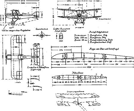
The strong dihedral (5 degrees) of the S. E.-5 wings (Figure 1.4) is evidence of an attempt to give the airplane inherent spiral stability. On spirally stable airplanes, if the pilot establishes a banked turn, the rudder and elevator have to be held in a deflected position to continue the turn. If the pilot centers the rudder bar and control stick, a correctly rigged airplane will automatically, but slowly, regain wings-level flight.

Contrasting Design Philosophies

Figure 1.4 The British paid attention to inherent spiral stability during World War I days, building 5 degrees of dihedral into the S. E.-5. (From Jane’s All the World’s Aircraft, 1919. Jane’s used a German source for these drawings since the S. E.-5 was still classified in Britain in 1919.)

The S. E.-5’s control surfaces had no aerodynamic balance and were difficult to move at diving speeds. Thin wing sections were used. The designers also had embraced a whim for numerology; the wings had 250 square feet of area and 5-foot chords; they were set at 5 degrees with respect to the thrust line, and so on.

Modern flight tests of World War I fighters (using the Shuttleworth Collection) give the S. E.-5A high ratings. Ronald Beaumont says this airplane was

perhaps the best handling fighter on either side, with excellent pitch and yaw control and inherent stability on both axes, and with light and responsive ailerons up to the quite high speed of 130 mph.

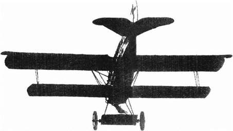
The Fokker D VII (Figure 1.5) had wooden-frame cantilever wings, almost without dihedral, with a thick airfoil section, an early result of Prandtl/Lanchester circulation theory. David Lednicer reported (2001) that the D VII wing airfoil was close to the Gottingen 418. The D VII had a steel-tube-welded fuselage and tail assembly. Horn balances (called elephant ears) were provided to lessen the pilot effort to deflect the ailerons, elevators, and rudder.

When Fokker flew the first version he realized he had created a dangerous airplane. Before the German Air Ministry officials could get a good look at it, he rebuilt it secretly in the hangar, moving the wings aft to make it less unstable, lengthening the fuselage, and modifying the vertical tail to incorporate a fixed fin. As a result of the D VII’s long tail moment arm; blunt-nosed, cambered airfoil sections; and mechanically limited up elevator

Contrasting Design Philosophies

Figure 1.5 The Fokker D-VII, built without wing dihedral, showing no concern for spiral stability. This machine had horn aerodynamic balances at the tips of all control surfaces, to reduce control forces. (From Progress in Airplane Design Since 1903, NASA Publication L-9866, 1974.)

deflection, stability and control at low speeds and climb rate were quite good. In its final form it pleased everyone so much that it was mentioned in the Treaty of Versailles as a military airplane that had to be surrendered to the Allied authorities, the only one so designated.

Jet and Rocket Effects on Stability and Control

Except for the V/STOL case, jet and rocket effects on airplane stability and control tend to be small compared with those for high-powered propeller airplanes. This is because of the absence of slipstream and direct propeller effects. Yet, they are not negligible. By the time the first jet aircraft were being tested, the necessary theory was in place. Two new factors needed to be accounted for-jet intake normal force and airstream deviation due to inflow into the jet or rocket exhaust.

4.8.1 Jet Intake Normal Force

The NACA engineer Dr. Herbert Ribner, who was also an important contributor to the body of knowledge on propeller forces in yaw, or propeller normal forces, provided the analogous theory for jet air intakes, or an algorithm for jet normal force (Ribner, 1946). Ribner’s jet intake normal force formulation is based on the mass flow of air into each jet intake and the angle turned by this air to get into the duct. This method neatly avoids having to estimate or measure pressure distributions inside and outside of the intake ducts, although the resultant normal forces must be generated by those pressures.

One interesting refinement is to take into account the upflow before each jet intake caused by the wing’s lifting system. In sideslip, the corresponding correction is for any sidewash ahead of the intake. Fortunately, wing upflow angles are readily available in chart form for any wing planform.

Herbert Ribner was active until 2001, spending winters at the Langley Research Center as a NASA Distinguished Research Associate and the rest of the year at the University of Toronto.

Jet and Rocket Effects on Stability and Control

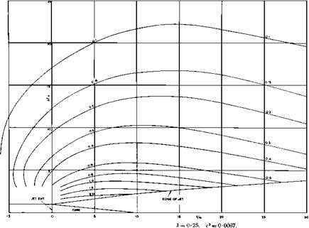
Figure 4.6 Calculated isoclines of the surrounding flow into a jet wake. Destabilizing downwash for tails mounted above the jet wake is indicated by the positive deviation angles. (From Squire and Trouncer, British R & M 1974, 1944)

Estimation from Drawings

6.2.1 Early Methods

The elements of stability and control prediction from drawings started to be avail­able as early as aerodynamic theory itself. That is, aside from elements such as propellers and jet intakes and exhausts, airplane configurations are combinations of lifting surfaces and bodies. However, it took some time before the lift and moment of lifting surfaces and bodies were codified into a form useful for preliminary stability and control design. Simple correlations of lift and moment with geometrical characteristics such as wing aspect and taper ratios and the longitudinal distributions of body volume were needed.

6.2.2 Wing and Tail Methods

For stability and control calculations at the design stage, the variations of lift coefficient with angle of attack, or lift curve slope, are needed for airplane wings and tail surfaces. Wing and tail lift curve slopes are to first-order functions of aspect ratio and sweepback angle, and to a lesser extent of Mach number, section trailing-edge angle, and taper ratio. The primary aspect ratio effect is given by Ludwig Prandtl’s lifting line theory and can be found as charts of lift curve slope versus aspect ratio in early stability and control research reports. The sweepback effect was added by DeYoung and Harper (1948).

However, classical lifting line theory for wings and tails fails for large sweep angles and low aspect ratios, even at low Mach numbers. A 1925 theory of supersonic airfoils in two-dimensional flow due to Ackeret existed, and also in the 1920s Prandtl and Glauert showed how subsonic airfoil theory could be corrected for subsonic Mach number effects. Both the Ackeret theory and Prandtl-Glauert subsonic Mach number correction theory fail at Mach 1. R. T Jones (1946) developed a very low aspect-ratio wing theory, valid for all Mach numbers, which applies to highly swept wings, that is, wings whose leading edges are well inside the Mach cone formed at the vertex.

6.2.3 Bodies

A fundamental source for the effects of bodies on longitudinal and directional stability is the momentum or apparent mass analysis of Max M. Munk (1923). This models the flow around nonlifting bodies such as fuselages, nacelles, and external fuel tanks in terms of the growing or diminishing momentum imparted to segments of the air that the body passes through. Pitching and yawing moments as functions of angle of attack and sideslip are found by this method.

Parameter Estimation Methods for Spins

The use of rotary balances of ever-increasing complexity for measuring aero­dynamic forces and moments in spins is avoided if aerodynamic forces and moments can be inferred directly from free-spinning model or airplane tests. Two promising approaches to this application of parameter estimation have been reported.

The first approach (Fremaux, 1995) extends the Gates-Bryant equilibrium or steady-state spin analysis to include the nonequilibrium angular acceleration terms p, q, and r and the spin acceleration term f2. Calculated aerodynamic moments by this method vary with time if the spin is oscillatory. The calculated moments oscillate about the Gates-Bryant values, which also can be measured independently on a rotary balance. This method requires the investigator to record rapid angular motions in a spin, feasible now with the advent of modern data-acquisition techniques.

A second parameter estimation approach for spins (Jaramillo and Nagati, 1995) appears to have been inspired by the finite-element methods used in structural analysis. A set of control points are established. Aerodynamic force coefficients at these points are correlated with local angles of attack and sideslip during spinning motions. These aerodynamic force (and moment) coefficientsare in effect influence coefficients. The influence coefficientsare found by minimizing cost functions based on the errors between measured vehicle accelerations and those calculated using forces and moments derived from the influence coefficients. Once the dimensionless influence coefficients are found, the method appears to have predictive capabilities. An improved version (Lee and Nagati, 1999) of the original method reduces the number of unknown parameters to be solved for by using static wind-tunnel test data.

Supersonic Altitude Stability

A somewhat strange lack of stability cropped up when airplanes began to operate at supersonic speeds above about Mach 2 at quite high altitudes. This showed up as an inability to control altitude and airspeed precisely in flights of the North American XB-70 Valkyrie and the Lockheed SR-71A. The Concorde SST with a maximum speed around Mach 2 is believed to have difficulties of this sort, as well. According to Glenn B. Gilyard and John W. Smith (1978), on the SR-71A:

Decreased aircraft stability, low static pressures, and the presence of atmospheric distur­bances are all factors that contribute to this degraded control. The combination of high altitude and high speed also contributes to an unfavorable balance between kinetic and po­tential energy, thereby requiring large altitude changes to correct for small Mach number errors when flying a Mach hold mode using the elevator control.

In simulating SR-71A supersonic altitude and airspeed control problems NASA found it necessary to add to the normal equations of aircraft motion inlet geometry effects on airplane motion, inlet operating characteristics up to the unstart boundary, and the afterburning equations for the two engines. While with these additions simulation presents no unusual difficulties, attempts to find suitable theoretical models are another matter.

The applicable body of theory begins with Lanchester’s 1897 analysis of phugoid mo­tion. Lanchester’s model, and the Bryan and Williams analyses that followed, neglected atmospheric density changes as an airplane’s height changes during a longitudinal oscilla­tion. F. N. Scheubel added density gradient to the mathematical model in 1942. In 1950, Stefan Neumark added the effects of thrust and sound speed variations with altitude to the equations.

While the classical Bryan-Williams model leads to a fourth-degree characteristic equa­tion, with both short – and long-period longitudinal oscillations, density gradient increases the characteristic equation degree to 5. A new aperiodic height mode appears, typically a very slow divergence (Figure 11.16). The height mode was first identified, or rather predicted, by Neumark. The supersonic altitude stability problems thus far encountered probably involve both the phugoid or long-period mode and the height mode.

Thrust effects are significant on both the phugoid and height modes (Stengel, 1970; Sachs, 1990). Aside from the effects of possible thrust offsets from the airplane’s center of gravity, the throttle-fixed variation in thrust with airspeed affects both the phugoid and height modes. Both modes are stabilized when thrust decreases with increasing airspeed, and vice versa.

Lanchester’s original analysis (Durand, 1934) assumes an airplane whose lift is always at right angles to the flight path and numerically proportional to the square of the airspeed. These simple assumptions and small-angle approximations lead to Lanchester’s phugoid motion, an undamped oscillation of period ^2n V/g, where V is the flight velocity and g is the acceleration of gravity.

Supersonic Altitude Stability

Figure 11.16 Effect of altitude on the phugoid and height modes of a hypothetical SST, cruising at a Mach number of 3.0. (From Stengel, Jour of Aircraft, Sept.-Oct. 1970)

However, the linear increase of period with airspeed predicted by Lanchester does not occur at high airspeeds. The reason is that the density gradient effect that Scheubel wrote about in 1942 becomes very important at high airspeeds. The phugoid period is shortened compared with the Lanchester case. In effect, as the airplane noses down, picking up speed and giving up potential energy for kinetic energy, higher density at the lower altitude increases lift, bending the path upward again. Higher density at lower altitudes acts as an extra spring, shortening the period.

A simplified model developed in 1965 by Lockheed’s John R. McMaster predicts drastic reductions in the phugoid period relative to the classic Lanchester values at high airspeeds. McMaster’s predicted period at a Mach number of 3.0 is about 150 seconds, compared with the Lanchester value of 401 seconds. Calculations by Stengel in 1970 for an SST configuration at a Mach number of 3.0 give a phugoid period of about 160 seconds, close to the McMaster value. A later simplified model (Etkin, 1972) shows a reduction from the Lanchester values, but not quite so large.

A formulation by Regan (1993) also corrects the Lanchester approximation for density gradient. Regan’s approximation may be derived from the small-perturbation longitudinal equations of motion of Figure 18.4 by adding a height degree of freedom and the height derivative dZ/dh, where Z is the Z-axis aerodynamic force and h is altitude perturbation from equilibrium flight. The Regan approximation for phugoid period is

Подпись: 400
Supersonic Altitude Stability
Подпись: Lanchester
Подпись: altitude= 800.

Supersonic Altitude StabilityMach number

Figure 11.17 Variation of approximate phugoid period with altitude and Mach number, including density gradient with height effects.

Period = 2ж(V0/g)/(2 – (1/p)(dp/dh)(Vo/g))1/2,

where V0 = equilibrium flight speed,

p = equilibrium air density,

g = acceleration of gravity at the equilibrium altitude,

dp/dh = density gradient with altitude at the equilibrium altitude.

This relationship is used to show the general trend of phugoid period with Mach number and altitude in Figure 11.17. Omitted are possible thrust effects. Figure 11.17 shows that density gradient causes the phugoid period to reach asymptotic values as airspeed increases indefinitely, which is at odds with the classical Lanchester approximation. Neglect of density gradient incorrectly doubles the approximated phugoid period at an altitude of 200,000 feet and Mach number = 2.

Figure 11.17 predicts a phugoid period of 154 seconds at Mach 3 at altitudes below 400,000 feet. This is close to McMaster’s predicted value for Mach number 3 and also to Stengel’sresultsin Figure 11.16. Eigenvalue calculationsfor the NASA GHAME hypersonic vehicle give remarkably close results to the Regan approximation for the phugoid period at Mach numbers above 2.

Flight test data that would support one simplified phugoid model or another seem not to be available, for good reason. Typically, airplanes are flown at those very high Mach numbers and altitudes with either or both altitude and Mach hold control loops active, as a direct result of the altitude stability problem. Loop closures modify the basic phugoid

Supersonic Altitude Stability

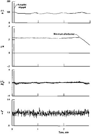
Figure 11.18 YF-12A altitude hold performance with an optimized autopilot, at Mach 3, altitude 77,500 feet. Altitude oscillation about the desired value is held to within plus or minus 25 feet. (From Gilyard and Smith, NASA CP 2054, 1978)

motion to the point where its period and damping would be difficult to detect, even if tests could be devised to measure periods as long as 160 seconds.

NASA flight tests of the YF-12A are encouraging in that properly designed and com­pensated altitude and Mach hold systems, working through the pitch and thrust controls, respectively, seem to be able to hold reasonably stable cruise conditions at Mach 3 (Figure 11.18). One physical limitation is instability in the atmosphere itself, notably tem­perature shears that change the indicated Mach number even though the true airspeed and altitude have not changed. Gilyard and Smith noted that baseline YF-12A altitude hold mode operation varied from day to day. “Occasionally altitude could be held reasonably constant; at other times, it diverged in an unacceptable manner.”

A related phenomenon was found in flight testing the XB-70 around a Mach number of 3. Indicated altitude changes of 1,000 feet were seen in 2 or 3 seconds, quite evidently the result of atmospheric temperature gradients, since the airplane could not have possibly changed altitude so quickly. To avoid having altitude and Mach hold systems chase after atmospheric instabilities, it may be necessary to smooth atmospheric data with inertial data or position measurements derived from satellites.

Wing Levelers

Wing levelers are single-axis automatic pilots typically used in general-aviation airplanesto prevent spiral divergence. John Campbell’s1952 NACA aileron centering device flown on a Cessna 190 was improved upon a few years later by another NACA group, which converted it to a wing leveler (Phillips, Kuehnel, and Whitten, 1957).

The Phillips device was an aileron trimmer, added to the earlier aileron centering system. The aileron trim point was moved at a slow rate by the output ofa yaw rate gyro (Figure 15.6). The slow 1.5-degree-per-second trim rate left the Dutch roll oscillation unaffected. The Cessna’s flight records showed that the trimming device could maintain a safe bank angle indefinitely, and even could provide a wheel-free recovery from banked attitudes, or effective positive spiral stability Phillips noted (1998) that NACA headquarters failed to file a patent application for the wing leveler, although a patent disclosure had been made. Without coverage by a valid patent, light-plane and autopilot manufacturers would not consider marketing the device.

Modern versions of the Phillips wing leveler device are available. Century Flight Systems, Inc., which started out as Mitchell, became Edo-Aire Mitchell, and finally split off as Cen­tury, produces the Century I wing leveler. This device is identical in principle to the Phillips wing leveler flown on the Cessna 190, with yaw rate gyro signals sent to an aileron servo. The ability to command turns and to follow a CDI (Course Direction Indicator) for VOR (VHF Omni-Directional Range), ILS (Instrument Landing System) localizer, or GPS (Global Positioning System) tracking has been added, making the Century I a simple autopilot.

The Modes of Airplane Motion

Small-perturbation airplane motions are characterized by modes, just as the dis­turbed motions of two spring-coupled masses are a composite of a high-frequency mode of motion in which the masses move toward and away from each other, and a low-frequency mode in which the masses move in the same direction. The five classical modes of airplane motion are found as factors of the airplane’s longitudinal and lateral characteristic equations (Jones, 1934).

The characteristic equations are of fourth or higher degree, so that factors must be found by successive approximations, rather than in closed form. The factors are either real or they occur in pairs, in conjugate complex form. The real factors are characterized by times to double or halve amplitude following a disturbance or by the inverse of the factor, the time constant. The complex factors are usually characterized by their periods or frequencies (damped or undamped) and by their dimensionless damping ratios. The five classical modes are

Phugoid, a low-frequency motion involving large pitch attitude and height changes at essentially constant angle of attack. Damping is low, especially for aerody­namically clean airplanes.

Longitudinal short period, a rapid, normally heavily damped motion at essentially constant airspeed. Damping is provided by wing lift in plunging, as well as horizontal tail lift in rotation. Rapid pitch maneuvers occur in this mode.

Dutch roll, a rolling, yawing, and sideslipping motion of generally low damping, especially at high altitudes.

Roll, essentially a pure rolling motion about the airplane’s longitudinal axis, heavily damped. The primary response to lateral controls is in this mode.

Spiral, a very slow divergence or convergence involving large heading changes, moderate bank angles, and near-zero sideslip.

Additional or combined modes appear in special circumstances, such as the supersonic height mode, discussed in Chapter 11. Notable combined modes are

Coupled roll-spiral or lateral phugoid, the conversion of two simple, aperiodic modes into one oscillatory mode. This mode occurs on airplanes with high effective dihedral and low roll damping (Ashkenas, 1958; Newell, 1965). It has been observed on some V/STOL and high-speed airplanes.

Lateral divergence, a degeneration of the Dutch roll mode into two aperiodic modes, one divergent.

Longitudinal divergence, a degeneration of the phugoid or short-period modes into two aperiodic modes, one divergent. For the phugoid case, the divergent mode is called speed instability or tuck; for the short-period case the divergent mode is called pitchup.

Kinematically constrained modes of motion are those in which some flight variable such as altitude or bank angle is suppressed entirely by theoretical control surface or thrust closed loops, representing pilot control actions. The object is to get approximate stability criteria for flight conditions where the pilot is actively controlling a variable. Two such modes are

Constrained airspeed mode, in which altitude is maintained by some control mo­ment, such as would be produced by the elevator. This produces a mathematical demonstration of speed stability (Neumark, 1957). The constraint results in a first-order differential equation in perturbation airspeed. There is an unstable real root for flight on the back side of the lift-drag polar, corresponding to lift coefficients above that for minimum drag. Section 2 of Chapter 12 discusses the implications of speed stability for naval aircraft.

Constrained yaw mode, in which zero bank angle is maintained by the ailerons (Pinsker, 1967). This constraint results in a first-order differential equation in perturbation yawing velocity. Pinsker demonstrated an aperiodic divergence at angles of attack greater than 18 degrees for an airplane with a low-aspect-ratio wing. This is similar to the nose slice experienced by some modern fighters. Stability of this aperiodic mode is governed by the LCDP parameter (Chapter 9, Sec. 15) Nv — (Nsa/LSa) Lv, where Nv and Lv are the yawing and rolling moments due to sideslip and NSa and LSa are the yawing and rolling moments due to aileron deflection.

The useful concept of airplane modes of motion has been extended to rotary-wing aircraft. In forward flight, their modes of motion are similar to those of fixed-wing aircraft. However, many of the usual stability derivatives disappear in hovering flight, giving quite different results for the modes of motion in hover.

By adding apparent mass effects to the stability derivatives, one can obtain modes of motion for lighter-than-air vehicles. Cook (2000) used earlier models by Lipscombe, Gomes, and Crawford and recent wind-tunnel data to derive modes of motion for a modern nonrigid airship.

Frequency Methods of Analysis

Frequency methods of analysis ushered in the age of modern airplane stability augmentation and autopilot analysis. In his 1950 Wright Brothers Lecture, Dr. William Bollay reminded us that the application of frequency-response methods to the airplane case came a full ten years after their use in the development of anti-aircraft gun directors. The footprints of the electrical engineering community in this field are still evident in the use of terms such as decibels and octaves in some airplane frequency-response studies.

Frequency response is the steady-state sinusoidal airplane motion perturbation in re­sponse to steady-state sinusoidal control surface input perturbation. Only the amplitude ratio and phase relationship of the two sinusoids are of interest. Frequency response of mechanical and electrical devices is readily found from the parameters of the linearized differential equations that describe the device’s motion or electrical properties. The formal mathematics that do this rest on the Laplace transformation, as explained in Chapters 3 and 4 of the classic 1948 text Principles of Servomechanisms, by Gordon S. Brown and Donald P Campbell.

Frequency-response analysis led stability and control engineers to an entirely new way to describe airplane dynamics, the transfer function. The transfer function is the mathematical operator by which any input function is multiplied to obtain the output function for that element. Transfer functions are numerical or literal expressions in the Laplace variable s. Transfer-function denominators are nothing but the characteristic equation, with Routh’s and Bryan’soperator X replaced by the complex Laplace variable s. Transfer-function numerators are governed by the input. Thus, the classical transfer function that converts elevator angle disturbances to pitch attitude disturbances is a second-degree polynomial in s divided by a fourth-degree polynomial in the variable s.

One of the first known applications of frequency response in airplane stability augmenter design was made by Roland J. White for the XB-47 yaw damper. White used the inverse frequency-response diagrams described by H. T Marcy in 1946, in an electrical engineering context. Over the years, frequency-response analysis has never gone out of fashion. For example, the demanding X-29A flight control system was designed using Bode frequency plot techniques by Grumman engineers led by Arnold Whitaker, James Chin, Howard L. Berman, and Robert Klein.

Frequency-response methods are used in some of the latest airplane flight control design methods, giving frequency response another lease on life. As detailed in a later section, singular value methods, associated with robust control theory, use frequency response.

Shielded Vertical Tails and Leading-Edge Flaps

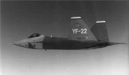
Radar return from an airplane’s bottom is an important consideration if the airplane is to operate where hostile ground radars rather than air – or space-borne radars are the major defense. Intersections of vertical tails with wing or fuselage surfaces act as corner reflectors, increasing radar returns. This is the reason why vertical tails are located entirely above wing surfaces on airplanes such as the Lockheed F-117A and F-22 (Figure 22.3).

Vertical surface shielding from radar by above-wing mountings has the undesirable effect of shielding the vertical surfaces from the airflow at large positive angles of attack. Premature departures into uncontrolled flight and spins result. Canting vertical tail tips outward, as on the F-117A and F-22 designs, is intended to put at least the tail tips out in unshielded flow at large positive angles of attack.

The importance of radar returns from an airplane’s bottom was brought out by Fulghum (1994). He reported that some reduction in the number of underwing doors, access panels, and drain holes was required to lower radar returns from the F-22. Radar returns from seams or junctures between fixed and movable surfaces are another consideration. Leading – edge flaps in particular are a cause of concern because of the lower seam between the flap and wing. The F-22 is equipped with leading-edge flaps. The F-22’s leading-edge flaps

Shielded Vertical Tails and Leading-Edge Flaps

Figure 22.3 The Lockheed F-22, showing its vertical tail intersections with the wings that are shielded from ground radars. The vertical tail tips are canted outward to retain some effectiveness at high angles of attack. (From Lockheed Martin Corporation)

Shielded Vertical Tails and Leading-Edge Flaps

Figure 22.4 NASA 8-Ft. Transonic Wind-Tunnel model ofaU. S. Air Force Multirole fighter concept, designed to have no vertical tail. Directional stability and control would be provided by thrust vectoring and low-radar-return control surfaces. (NASA photo 93-01934)

are an important contributor to the airplane’s air combat capability, including its reported ability to fly stably at an angle of attack of 60 degrees. Leading- and trailing-edge flaps are programmed with Mach number and angle of attack to maintain lateral and directional stability.