Category An Introduction to THE THEORY OF. AEROELASTICITY

POSSIO’S INTEGRAL EQUATION

The results of the preceding sections can be combined to give an integral equation expressing the boundary-value problem of an oscillating airfoil. The total vertical component of velocity due to a lift distribution L(£, t) is, according to Eq. 16 of § 14.3, given by the Cauchy integral:

v{x, 0, 0 = Г Щ, t) K(M, x~£)d£ (1)

Pou J-1

where

v(x, 0, t) = v(x)eiu>t, Щ, 0,-t) = Щ)еіиЛ

The function v(x, 0, t) is given by the boundary condition (Eq. 7 of § 13.2) for a given airfoil in a given oscillation mode. The problem is then to determine Щ, t) from Eq. 1 under the side condition that L 0 at the trailing edge f = 1 (the Kutta-Joukowski condition).[39] Equation 1 is called the Possio’s integral equation. f The kernel K(M, x — f) depends on the Mach number M, the reduced frequency к = 1 w/U, and the dis­tance x — f. It has a singular point at x = f.

Possio’s equation is a special case of a general type of singular integral equation studied earlier by Carleman. J It is a Cauchy-type integral equation of the first kind. With the imposition of the Kutta condition at the trailing edge, a unique solution is known to exist. Several methods of reducing this equation into an ordinary (nonsingular) integral equation are known. But so far no solution of Possio’s equation has been obtained in closed form. Numerical or graphical methods must be employed.

For this purpose the singularities of K(M, z) may be isolated in the following manner according to Schwarz:1416

F(M) , ,

K(M, z) = – Д—’ + і G(M) log |z| + Д(М, z)

where

z = kx (k = reduced frequency)

F(M) Vl – M G{M) =—————— Д=—

2w 2ттл/і – Мг

In particular, at zero Mach number,

where Ci(z) and Si(z) are the cosine and sine integrals, respectively.* Д(Л/, z), defined by Eq. 2, is a continuous function of z. Numerical tables of the functions К and Д are published by Possio, Dietze, Schwarz, and Schade. f

A different separation is given by Dietze:14,2

K(M, z) = AKyiM, z) + AK. JM, z) + ДО, z) (5)

where

ДД(М, 2) = ~ + kn – I – k12 logz + z(kla + к, л log |z|) (6)

The real and imaginary parts of the coefficients k2n are tabulated in Dietze’s paper.14,2

DOWNWASH CORRESPONDING TO A DOUBLET IN ACCELERATION POTENTIAL

Let us consider the velocity field corresponding to the acceleration potential of a vertical doublet. Without loss of generality we shall put the doublet at the origin.

For an oscillating field with a time factor еш, the vertical component of velocity v is related to the vertical component of acceleration ay through the equation (§ 13.2, Eq. 12)

This is the velocity downwash field corresponding to a doublet at the origin. If the doublet is situated at (f, 0), we have to replace x in the above formulas by x — f.

LIFT AND THE STRENGTH OF DOUBLET IN ACCELERATION POTENTIAL

In the linearized thin-airfoil theory, the discontinuity of the pressure field across the airfoil can be represented by a layer of doublets, the strength of which varies with time. In order to find the relation between
the lift distribution and the oscillation mode, the lift force and the induced downwash velocity corresponding to a given distribution of doublets must be known. These relations will be derived in the present and the next sections.

First let us remark that, in the airfoil theory, the doublets are distributed over a surface (a line segment along the x axis in the two-dimensional theory). Consider, then, a line distribution of “doublets” along the x axis from x = — 1 to x = + 1. Let B(xa) be the strength per unit length of the doublet distribution at a point (x = x0, у = 0) on the airfoil. The total acceleration potential is then

ф(х, у, t) = B(x0) sin в dx0 (1)

where

Г = ]Pa ~ Xo)2 + ^ <2)

Let us evaluate the local lift distribution acting on a doublet element of length 2e situated at x = £, є being a small number compared with 1. Let L(x, t) be the lift per unit length acting bn the doublet layer at (ж, 0). Then the lift force on the element concerned is 2еЩ, t). Referring to Fig. 14.1,

Fig. 14.1. The region of integration.

let us take a curve C which is a narrow rectangle of height 2d and length 2e. According to Newton’s law, the rate of change of momentum of the fluid enclosed in C is equal to the external force acting on it. The latter consists of the pressure force acting on the boundaries of C and the lift force exerted by the doublet layer. Now, when the strength B(x0) is so chosen as to make the resulting flow field correspond to a physical prob­lem, the acceleration potential ф(х, у, t) must satisfy the kinematic bound­ary conditions on velocity and acceleration. In particular, the vertical acceleration 5ф/ду must be finite over the airfoil. Therefore, the rate of

(5)

(6)

6->0

The limit d -> 0 can be taken inside of the integral. Now

lim ф(х, (5, t) = lim eiwl Г B(x0) sin в dx0

6-е 0 6-+0 J-1

( ҐХ-В ҐХ + С Л1

= lim eiwt j + + (7)

d—+0 J — 1 Jx — € Jx+e)

When x — a:0| > e > 0, Нф2)(о>г’) is finite, but sin в tends to zero as <5 -» 0. Hence, the first and the last integrals in the bracelets of Eq. 7 vanish in the limit as long as d є. Applying the mean-value theorem to the middle integral in the bracelets of Eq. 7, we obtain

sin в H^wr’) dxn (8)

x—B

where 1 is some number between integral, notice that

Нф2)(г) = — — – z log z + (power series in г)

and

Substituting this result into Eq. 6, we obtain

ff+c 2i82a

2єЩ, t) = 2p0 е“(г+аЛ£) B(x +Xe)dx (- 1 < Я < 1)

«/| — e Cl)

Since Д(а; + Хє) is a continuous function, we obtain, in passing to the limit г -> 0

Щ, t) = eiat В(ф) (12)

CO

This formula relates the local strength of a continuously distributed doublet layer to the local lift force per unit length. It is seen that they are directly proportional.

The horizontal force acting on the distributed doublets with vertical axes is zero.

GENERAL EQUATIONS AND ELEMENTARY SOLUTIONS

In a subsonic flow, the main-stream Mach number M — Uja is less

than 1, and the quantity _______

0 = Vl – M2 (1)

is real and positive. Equation 2 of the last section can be written as

1 32ф 2 M 2 32ф 32ф

3? + ~7 dxdt ~ ^ 5×2 = d^

which can be simplified by the following transformation:

where

a = M/iffta)

Equation 2 then becomes the classical wave equation

фтт ~ фїЄ ~f’ Фчч

Introducing polar coordinates

£ = / cos в, fj = r’ sin в

/ = л/£2 + jj2 = ~ Vx2 + /? V

p*a

—■(і)=–■(?)

we have

, . 1 1

фгт — фгУ + -,Ф,’ + – Т^фы

Ґ г

Assuming a solution of the form

ф(/,0,т) = (9)

we see that the equation governing R(r’) is

The brace { } means that either of the two functions enclosed in it may be taken.

The Hankel functions Hna)(cor’) and Яи(2)(а>/) (also called Bessel functions of the third kind) are tabulated in several treatises.* They are

* For example, see Jahnke and Emde, Tables of Functions. Dover Publications.

complex valued for real arguments. We shall not discuss the general properties of the Hankel functions here.* But the following salient properties are needed for the following discussions:

1. The conjugate complex of Hna)(reie) is Hj2)(re~ie) [and not Hna)(re~l6)]. If Hna)(z) is known, tfn(2)(z) can be obtained from the formula

HKVz) = 2Ш – H™(z) (12)

where Jn(z) is the Bessel function of the first kind of order n.

2. For very small arguments (|z| 1),

7/ cz

~ ——- log— (c ~ ev = e0*5772 = 1.781)

7Г 2

H™(z)~- (13)

7TZ

Hnm(z) ~ – і (n — 1)! (-) (и, integer, Ф 0)

7Г Zl

The ~ sign means that, in the Laurent’s series expansion of the Hankel functions, the sum of all the other terms are of order smaller than the first term.

3. For very large argument, the dominant terms of the asymptotic representation of the Hankel functions are (|z| 1):

tf„a)(z)

We can now examine the physical meaning of the solution 11. Con­sider the case n — 0. The solution is

According to Eqs. 12 and 13, it is seen that the absolute values of H0a)(r’) and Я0(2,(/) become infinitely large when r’ -» 0. Hence, both terms of Eq. 15 behave like a source at the origin. To see the properties of the waves corresponding to these two elementary solutions, we examine the solution at large values of cor’. The asymptotic representation for the

* An exhaustive treatment is given by Watson: Bessel Functions, Cambridge Univ. Press. An elegant introduction sufficiently developed for physical applications can be found in Chapter IV of Sommerfeld’s book: Partial Differential Equations, Academic Press (1949).

functions H0a)(a>r’) and #0<2)(cw’) are given by Eqs. 14 by setting n = 0. Hence, asymptotically, at large distance from the source, the acceleration potentials are

ф1 = A(lff0a)(oj/)eim(l+ax) ~ A0 J-2—. e -<-nli)i+iuxxx

—– (16)

<L = A0H0{i)(mr’)eMt+,xx) ~ An J—- eW4)i+»««* eMt-n

N TTU>r

The factor t + / remains constant when t increases if the distance r decreases with suitable speed. Hence, ф1 represents an incoming wave, converging toward the source at the origin. Similarly the factor t — / in ф2 indicates that ф2 represents a wave radiating from the source. If the source at the origin is regarded as the only cause of disturbance in the flow field, we must impose the condition that waves can only radiate out from the source, and, hence, we must discard H0{l)(a>r’) as a physical solution.

The case n = 1 can be similarly examined. The solution that repre­sents waves radiating out from the singularity is given by

The cos в term on the right-hand side is antisymmetrical with respect to the у axis, while the other, sin в, is antisymmetrical with respect to the x axis. Since H^Hcor’) tends to infinity when r —> 0, so the solution

ф(г 0, t) = В sin в Я1(2)(иг’)еіш((+“) (18)

represents a “doublet” at the origin, with axis perpendicular to the x axis, while the other solution involving cos в represents a doublet at the origin with axis perpendicular to the у axis.

If the singularity (a source, a doublet, etc.) is situated at the point (a?0, Уо) instead of at the origin, it is necessary to replace the x and у occurring in the above solutions by (x —■ x0) and (y — y0), respectively. In particular, / should be replaced by

/ = i_ V(x – x()f + (?iy – y, f (19)

OSCILLATING AIRFOILS IN TWO-DIMENSIONAL. COMPRESSIBLE FLOW

An oscillating airfoil in a two-dimensional compressible flow will be treated in this chapter. All the hypotheses made in § 13.1 regarding the linearization are again assumed here.

The linearized equation for the acceleration potential <f>, referred to a frame of reference at rest relative to the fluid at infinity is given by Eq. 15 of § 12.5. If the coordinate system is moving with a speed U in the negative ж-axis direction relative to the fluid at infinity, the field equation of small disturbances can be obtained by transforming that equation according to the Galilean transformation

x — x’ — Ut’, у = у’, t = f

The following field equation is obtained in this new coordinate system for a two-dimensional flow in the (x, y) plane:

(2)

where the primes are omitted. For an observer fixed on the moving coordinates, the fluid at infinity has a velocity U in the positive a;-axis direction, a is the speed of sound in the undisturbed flow.

As in the last chapter, the principle of superposition is valid, and it suffices to treat oscillating airfoils of zero camber, zero thickness, and at zero mean angle of attack.

In a subsonic flow, (U < a), an elementary solution of Eq. 2 was obtained by Possio who derived an integral equation governing ф and obtained some numerical results by a method of collocation in 1937. These calculations were repeated and extended by Frazer (1941) and Frazer and Skan (1942). The kernel of Possio’s equation was tabulated by Schwarz (1943). Approximate solutions were proposed by Schade (1944), Dietze (1942-44), and Fettis (1952). An exact solution of Possio’s equation in closed form is yet unknown.

A different approach to the subsonic oscillating-airfoil theory was pursued independently by Reissner and Sherman (1944), Biot (1946),

Timman (1946), Haskind (1947), and Kiissner (1953). The boundary – value problem was directly attacked by the introduction of (confocal) elliptic coordinates. An explicit solution of the problem can then be obtained in terms of Mathieu functions. A great deal of mathematical work is required, however, to bring the solution into a form suitable for numerical calculations.

In contrast to the subsonic case, the linearized supersonic case is extremely simple. This is so because of the simple physical condition that (in the two-dimensional case) the flows above and below the airfoil are independent of each other, and that the flow over the airfoil is inde­pendent of the conditions in the wake. The corresponding differential equation, of the hyperbolic type, can be solved by a number of methods. The first solution was given by Possio in 1937 by a method of super­position of sources and sinks. Von Borbely solved the problem by the method of Laplace transformation (1942), and Temple and Jahn solved it by Riemann’s method (1945). Extensive numerical results were obtained by Schwarz, Temple and Jahn, Garrick and Rubinow, and others (see bibliography).

In §§ 14.1 through 14.4, Possio’s integral equation for the subsonic flow will be derived in a manner used by Biot, Karp, Shu, and Weil.14-1 Approximate methods of solution of Possio’s equation will be outlined in § 14.5.

The supersonic case is discussed in § 14.6, where, following Stewart – son,14-40 the Laplace transformation method is used. In § 14.7, the results known so far are tabulated for a quick reference.

The lift of an oscillating wing can also be computed from the indicial responses to suddenly started motions. It turns out that, if the main­stream Mach number is close to one, it is simpler to calculate the indicial responses. Heaslet, Lomax, and Spreiter14-24 have shown (1949) how the lift due to a harmonic vertical-translation oscillation of a flat plate in a flow with main-stream Mach number equal to one can be calculated according to the linearized theory.

TABULATION OF RESULTS—INCOMPRESSIBLE FLOW

Formulas and numerical tables of the aerodynamic coefficients for an airfoil with flap and tab, whose hinge lines do not necessarily coincide with their respective leading edges, have been published by many authors. The most important references are:

Dietze:13Л1,1312 Luftfahrt-Forsch. 16, 84-96 (1939); 18, 135-141 (1941). W. P. Jones:1316,1317 Aeronaut. Research Council R. & M. 1948 (1941); R. & M. 1958 (1942).

Kiissner and Schwarz:13-23 Luftfahrt-Forsch. 17, 337-354 (1940). Trans­lated as NACA Tech. Memo. 991.

Theodorsen13-32 and Garrick:13-33 NACA Rept. 496 (1934); Kept. 736 (1942).

The most comprehensive numerical tables are published by Kiissner and Schwarz in the reference named above. The relations between the special functions tabulated by various authors are listed in a paper by W. P. Jones.1317

For flutter calculations, Smilg and Wasserman’s tables of Lh, La, etc., which are derived from Kiissner and Schwarz’s results, are widely used. These tables are contained in the following references:

AAF Tech. Rept. 4798, U. S. Air Force, by Smilg and Wasserman,6-20 (1942).

Introduction to the Study of Aircraft Vibration and Flutter, book by Scanlan and Rosenbaum.619

While both sealed and unsealed gaps between the main wing and the flap and the control tab are considered in Kiissner and Schwarz’s paper, only unsealed gaps are considered in Smilg and Wasserman’s. Furthermore, the tab hinge line is assumed to be located at the tab leading edge in

(b) Kiissner and Schwarz’s airfoil

Fig. 13.6. Comparison of Dietze’s aerodynamically balanced flap with Kiissner’s.

Reference

Duncan, Collar. Ref. 13.34

Theodorsen. Ref. 13.32

Kussner, Schwarz, Ref. 13.23

Dietze, Ref. 13.11. 13.12

Frazer, Ref. 7.31

Cicala, Ref. 13.7, 13.8

Lyon, Ref. 15.3

Kassner, Fingado, Ref, 6.15

Jones, Ref. 13.17

Scanlan,

Rosenbaum.

Smilg, Wasserman, Ref. 6.19. 6.20

* This Book

Chord

c

2b

21

/(= Iri>

с

I£= 2/) or/

£([38]=20

t

c

2b

c = 2b

Free-stream velocity

W

V

V

V

V

V

F

V

V

V

17

Circular frequency

P

kv

b

V

о

о*=

п

V

V

ш(= 2w/)

a>

a>

Reduced frequency

A

2

к

– ito

(Of

А

2

a>

а>

2V

a>

T

к

к

Translational motion at reference point

z

h

Aleivt

6

Z

rjL оті]

Й/

z

h

h

Rotational motion of airfoil

0

a

BeiH

p

в

а

0

ф

0

а

a

Lift vector (circulation function)

C

l – h T 2

і 4- г 2

– 1C

і – А

1 – А

P

C

C

C

Real part of C(Ar)

-!

F

І + r 2

1 + Г 2

А

і — А’

1 – А’

A

A

F

F

Imaginary part of C(k)

AG

2

G

T"

2

T”

2

– В

– А*

А’

– В

– В

G

G

Lift (+ upward)

-Z

– P

К

— Р

-Z

А»

А*

– z

-L’

L

Pitching moment (+ nose up)

M

Ma

– Me

М

м

– М

М

M

M’

Mx0*

414

AAF Tech. Rept. 4798. The tables in AAF Tech. Kept. 4798 for tab oscillations and tables for aileron with e < 0, where eb is the coordinate of the aileron leading edge aft the mid-chord point, are not reproduced in Scanlan and Rosenbaum’s book.

Dietze’s results for the aerodynamic overhang of the control surfaces differ from those of other authors by the assumption that the overhang part of the flap is bent and faired with the main wing, and that of the tab is faired with the flap. See the comparison in Fig. 13.6.

The notations used by several authors are listed in Table 13.1.

KtjSSNER-SCHWARZ’ GENERAL SOLUTION

Подпись: У =Дх)еш The “upwash” v on the airfoil is therefore given by By following the method of the previous sections, the aerodynamic force acting on a skeleton airfoil oscillating with arbitrary mode can be computed. Let the airfoil be located from x = — 1 to x — + 1 as in § 13.2, and let the harmonic oscillation of the points on the airfoil be described by

Подпись: t 00, ' JP0 + COS «0 V 1 J Подпись: v(6, 0 = - UeM
Подпись: (3)

It is convenient to introduce a new variable x = cos 0* and consider v as a function of 0 and t. We can express v by a Fourier series:

Подпись: where

UeiatP0= — I v(0,t)d6

7T JO

Подпись: (4)UeM Pn = – і I v(6, t) cos и0 t/0

7Г JO

With the upwash given in this form, the acceleration potential ф and the pressure distribution p can be determined as in the previous sections. The lift distribution can be written as

Подпись: (5)Подпись:/(0, I) = pU2emt ^2a0 tan~ + 4^Гая sin ndj

Kiissner and Schwarz13-23 obtained the following relations: a0 = C(k)(P0 + jPj) — P

+ = ^ + Pn~Tn Pn+1 (n – ^

where C(k) is the Theodorsen’s function defined by Eq. 19 of § 13.4. (Kiissner writes (1 + T)j2 for C(k).)

2 [[36]

– v(6, і

TT Jo

KtjSSNER-SCHWARZ’ GENERAL SOLUTION Подпись: (7) (8)

Using Eqs. 6, Kiissner and Schwarz derive the following general solution which is independent of the Fourier coefficients :f

The integral in Eq. 7 is defined by its Cauchy principal value. The total lift is then given by

L = J l • dx = J /(0, t) sin 0 d& (9)

Подпись: M. KtjSSNER-SCHWARZ’ GENERAL SOLUTION

and the moment about a point x0 — cos is

The result of integration gives the following expressions for the total lift and the stalling moment about the mid-point corresponding to the upwash given by Eq. 3:

Подпись: (И)L = IrrpU^ [(/>„ + PL) C(k) + (P0 – P2) |

Aft/, = rrpU^ jP0 C(k) – PJ1 – C(k)] – (PL – P3) t – P* (12)

It is interesting to notice that the resultant lift depends on only the first three coefficients in Eq. 3, and the resultant moment on the first four. This is, in fact, connected with the general expression of the complex potential as given by Eq. 8 of § 13.3. It may be verified that the total lift depends only on the imaginary part of the coefficients A0 and A1, and the total moment depends only on the imaginary part of the coefficients A0 and A2.

Example. Lift Force Due to a Sinusoidal Gust. Let us consider the lift acting on an airfoil, flying at a uniform speed and entering a sinusoidal gust. If the coordinate axes are fixed on the airfoil, the vertical gust may be represented by a velocity distribution

w(x, t) = Weiw(t-xlL’] (13)

which expresses the fact that a sinusoidal gust pattern, with amplitude W (a constant), moves past the airfoil with the speed of flight U. If the wave length of the gust is /, the frequency со with which the waves pass any point of the airfoil is

со = lirUjl (14)

If the gust velocity w{x, t) is considered positive upward, the relative velocity at any point on the airfoil to the fluid (measured positive upward) is

v(x, t) = — Ц/е™1е-Цш! и)сов0 = _ ц/еішІе-ік cos в (15)

where the transformation x — cos в has been made for points on the

airfoil. Equation 15 may be put into the general form of Eq. 3 by the identity[37]

CO

eiz cos 0 = Ja(z) + 2 2* VB(z) cos nO (16)

n~l

Подпись: v(x, t) = - WeiM Подпись: J0{k) + 2 )(- i)nJn(k) cos nO Подпись: (17)

where Jn{z)’s are Bessel functions of the first kind. Putting z = — к and noting that Jn(— z) = (~)nJn(z), it is seen that, according to Eqs. 15 and 16,

By comparing Eqs. 3 and 17, the expressions for the lift and moment can immediately be written according to Eqs. 11 and 12. If the chord length of the airfoil is c instead of 2, the lift and moment per unit span are

L = – npcUWe^ {[/0(£) – / /#)] C(k) -f – Шк) + J2(k)] 1} (18)

M1/a = Q рсЧіИ’е™1 {/„(A:) C(k) + пт – ОД]

+ [iUk) + iJ3(k)]~ + J2(k)] (19)

These expressions can be simplified by means of the recurrence formula for Bessel functions,

Подпись:Подпись: (21)Подпись: (22)2 nJn(z)lz = Jn~i(z) + Jn+i(z) from which the following results are obtained:

[J0(k)+J2(k)]j = iJL{k)

[iJL(k) + iJ3(k)]^= – .ОД

Therefore Eqs. 18 and 19 are reduced to

L = T! pcUWeitot ф(к) and

M4 = L–

h 4

where

ф(к) = [/„(*) – I Uk)]C{k) + / Aik) (23)

Clearly, the resultant lift acts through the ^-chord point from the leading edge. The factor тгрсІІф(к) represents the frequency response (admit­tance) of the lift to the gust. Writing

C(k) = F+iG (24)

where F, G are real functions of the reduced frequency k, we have

ф(к)* = (V + Л2)(Л + G2) + A2 + 2J0AG – 2J2F (25)

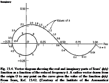
Подпись: Imaginary Fig. 13.4. Vector diagram showing the real and imaginary parts of Sears’ ф(к) function as a function of the reduced frequency k. A radius vector drawn from the origin О to any point on the curve gives the value of the function ф(к). From Sears, Ref. 13.42. (Courtesy of the Institute of the Aeronautical Sciences.)

The function ф(к) is plotted as a vector diagram in Fig. 13.4. The function |^>(fc)|2 is plotted in Fig. 13.5. An approximate expression,

which agrees with the power-series expansion of Eq. 25 up to the first power in к and with the first term of the asymptotic expansion of Eq. 25 is

Подпись: m2

a A к

(a = 0.1811) (26)

Expression 26 approximates Eq. 25 closely over the whole range of к from 0 to oo. A simpler approximation is

Подпись: №)2 =Подпись: (27)1

1 + 2ттк

A comparison of Eqs. 25, 26, and 27 is given in Fig. 13.5. It is seen that Eq. 27 agrees fairly well with the exact expression 25, except for small values of k.

The solution 22 is due to Sears.13-42 The approximation 27 is due to Liepmann.911

Fig. 13.5. Comparison of approximate expressions of |#A)|!.

AIRFOIL PERFORMING VERTICAL-TRANSLATION AND ROTATIONAL OSCILLATIONS[35]

Let us consider first the vertical-translation oscillations. Using the complex representation of harmonic oscillations, we may describe the airfoil surface by the equation

У = Уфеш (1)

where y0 is a real number representing the ratio of the amplitude of the vertical motion to the semichord b of the airfoil which is taken as 1 in the following analysis. y0 is therefore dimensionless. It is convenient for the following derivation to express the circular frequency m in terms of the nondimensional reduced frequency k. Using the semichord b — 1 as the characteristic length, we define

, cob ft)

Hence, Eq. 1 may be written as

У = Уп eWU (їй)

On the airfoil, the boundary values of the vertical velocity and acceleration of the flow are, according to Eqs. 7 and 8 of § 13.2,

Dy

Dt


AIRFOIL PERFORMING VERTICAL-TRANSLATION AND ROTATIONAL OSCILLATIONS[35]

v‘


(2)


Dhy Dt2


– U2k2y0 eiukt


AIRFOIL PERFORMING VERTICAL-TRANSLATION AND ROTATIONAL OSCILLATIONS[35]

AIRFOIL PERFORMING VERTICAL-TRANSLATION AND ROTATIONAL OSCILLATIONS[35]

In all the equations that follow, the factor егШ occurs in every term; hence, it will be omitted in writing.

The conformal mapping method described in § 13.3 may be used. In the transformed plane (i. e. the £ plane), the normal component of the acceleration on the airfoil (the unit circle) is, according to Eq. 4 of § 13.3,

a’n№ = 1) = — U2k2y0 sin 0 (3)

An inspection of series 8 of § 13.3 suggests that, for the present problem, the proper form of the complex acceleration potential tv(£) is

AIRFOIL PERFORMING VERTICAL-TRANSLATION AND ROTATIONAL OSCILLATIONS[35]

AIRFOIL PERFORMING VERTICAL-TRANSLATION AND ROTATIONAL OSCILLATIONS[35]

Подпись: where Подпись: Ф = фі + ф& Ч> = Ч>1 + Ч> 2 . sin б. cos 0, Фі ~ A- -1, 4>і = А 1 fl ri Фг — „ sin в cos в в , г % = В Г Подпись: (5)

This will be verified below. According to Eq. 4, the real and imaginary parts of w(£), i. e., the acceleration potential and its conjugate function are

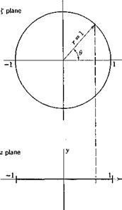
the meaning of г, в, /у, being shown in Fig. 13.3. On the airfoil, i. e., on the unit circle in £ plane, we have

r — 1, rr = 2 cos

AIRFOIL PERFORMING VERTICAL-TRANSLATION AND ROTATIONAL OSCILLATIONS[35]

The corresponding normal components of acceleration are therefore

AIRFOIL PERFORMING VERTICAL-TRANSLATION AND ROTATIONAL OSCILLATIONS[35]

The second relation of 6 is evident. The first of Eqs. 6 can be verified by direct substitution. It can also be recognized through the fact that is

a constant on the unit circle (a streamline of the doublet), and that <f>l = const and грі — const curves are orthogonal. The constant potential lines are therefore normal to the unit circle, and the normal derivative of фг vanishes on the circle.

Comparing Eqs. 6 and 3, we see that the normal acceleration on the airfoil is satisfied by taking

В == U2k2y0 (7)

The constant A is left undetermined, giving us freedom to satisfy the kinematic condition on the velocity component.

Now the у component of the velocity is related to the у component of acceleration by Eq. 12 of.§ 13.2:

Подпись: (8)e~ikx ґх

V =j= ——— ay(x)elkx dx =

U J — 00

Подпись: iUky0 = AIRFOIL PERFORMING VERTICAL-TRANSLATION AND ROTATIONAL OSCILLATIONS[35] Подпись: (/ж Подпись: (9)
AIRFOIL PERFORMING VERTICAL-TRANSLATION AND ROTATIONAL OSCILLATIONS[35]

Hence, at a point x = — 1 + £ on the airfoil (0 < £ < 2), the boundary condition on velocity is, from Eqs. 2 and 8,

This equation must be satisfied for all values of £. Differentiating Eq. 9 with respect to £ and using Eqs. 2, we can readily show that the derivatives on both sides of the equation vanish identically. Hence, Eq. 9 is a true identity in the variable £. This means that, if Eq. 9 is satisfied at one point, it is satisfied for the entire airfoil. In particular, we can take £ to be a small number tending to zero. To evaluate the integral in Eq. 9, since the term Э^/Эж introduces a divergent singularity at the leading edge, we shall first integrate the terms containing dyjdx by parts to obtain a convergent integral. The limit for £ -> 0 in Eq. 9 then becomes

[<" C-l+ T К – tsr) * (,0)

YT and y>2 in this expression must be evaluated on the physical plane, (i. e., the z plane). They must be transformed from their values on the £ plane, given by Eqs. 5, back to the z plane. Now, on the circle ] £| = 1, Yfi is a constant

A

(Vi)|{i=i — 2

Подпись: 2
AIRFOIL PERFORMING VERTICAL-TRANSLATION AND ROTATIONAL OSCILLATIONS[35]

while yij -» 0 when rx = x + 11 -> oo. The first term on the right-hand side of Eq. 10 is equal to — A/2U. To evaluate the remaining term in Eq. 10, note that the conformal transformation 1 of § 13.3,

has the inverse transformation

£ = z + Vz2 — 1

where Vz2 — 1 is taken as the principal branch that assumes real positive values when z is real and > 1. On this branch, Vz2 — 1 takes negative
real values when z is real and < — 1. Hence, on the negative real axis, where r — — £, rx = — 1 — 1 and z = x, (x < — 1) we have

r — —x–Vx2 — 1

rx — — X — 1 + Vx2 — 1

AIRFOIL PERFORMING VERTICAL-TRANSLATION AND ROTATIONAL OSCILLATIONS[35]
Note further that в — вх — тг in the same range on the negative real axis. Substituting these values of r, rx, 6, 0X into Eq. 5, we see that, when x < — 1,

Подпись: Kx(iz) = Подпись: dS AIRFOIL PERFORMING VERTICAL-TRANSLATION AND ROTATIONAL OSCILLATIONS[35] Подпись: -izS Подпись: (15)

Differentiating Eq. 13 with respect to iz, we have

Comparing Eqs. 12, 13, and 15, we see that, if A: is a complex number whose argument satisfies the condition (— тг < arg A: < 0):

Подпись:f-i л Г Р-Щ

Vi dx = – ~2 + Ko(ik) –

Подпись: Similarly,

f eiix dx = В f (1 + —J………………………………………. dx

Подпись: = - u2k% Подпись: Uik) Подпись: (17)

J — со ОЯ/ «/ — oo – у/^«2 __ J J

But the final expressions in Eqs. 16 and 17 are analytic functions of k, regular over the entire Argend plane if that plane is cut along the negative real axis. Hence, by the principle of analytic continuation, Eqs. 16 and 17 are valid also when arg к — 0. Combining Eqs. 10, 16, and 17, we obtain

A — — 2ilPky0 C(k) (18)

AIRFOIL PERFORMING VERTICAL-TRANSLATION AND ROTATIONAL OSCILLATIONS[35] Подпись: (19)

where

The function C(k) is often referred to as Theodorsen’s function. Its numerical value is given in Table 6.2.

All boundary conditions concerning the velocity and acceleration are now satisfied. Since the function tv(£), given by Eq. 4, is continuous at the trailing edge, the Kutta condition is also satisfied. Thus the solution is completed. From Eq. 5 the acceleration potential is

Ф=- 2iU*ky0 C(k) + U*k*y0 — (20)

ri r

The pressure distribution on the airfoil is obtained from the relation p = — рф by putting r — 1, rx — 2 cos 61, in the above equation. Since ф is antisymmetric in y, the pressures acting on the upper and lower side of the airfoil are of opposite sign and the lift distribution l (positive upward) is equal to — 2p.

Подпись:Подпись: (21)ik C(k) tan – + k2 sin I

The complex amplitude of the total lift can be obtained by an integration* L =J Idx / sin 0 dd = nplPyfc2 [l -1 C(fc)] (22) The moment about the mid-chord point is (positive in the nose-up sense) М/ = — f lx dx — — f l cos 0 sin в dO

U J-i Jo

= – TrplPiygk C{k) (23)

A comparison between Eq. 22 and Eq. 23 shows that part of the lift that is proportional to C(k) has a resultant acting at the ^-chord point. This part of the lift can be identified as that caused by the bound vorticity over the airfoil. The other part of the lift has a resultant that acts through the mid-chord point. This latter term arises from a noncirculatory

* Lift = Leiat.

origin, and is equal to the product of the apparent mass and the vertical acceleration. The apparent mass is independent of the flight speed. For a flat plate the mass of the fluid enclosed in a circumscribing cylinder having the airfoil chord as a diameter is the theoretical apparent mass associated with the vertical motion.

The rotational oscillations can be solved in a similar manner. Let the skeleton airfoil, which executes rotational oscillation with a small ampli­tude about the origin (the mid-chord point), be represented by the equation

у = — anxeimt — — к(pceivu (24)

The boundary values of the vertical velocity and acceleration of the flow on the airfoil are, accordingly,

v’ = – a0Ueam(ikx і – 1) (25)

a’y = aaU2keikl! t(kx – 2і) (26)

AIRFOIL PERFORMING VERTICAL-TRANSLATION AND ROTATIONAL OSCILLATIONS[35] Подпись: (27)

When the airfoil is transformed into a unit circle on the £ plane, the complex acceleration potential in this case assumes the form

The constants В and C are easily seen to be

В = Ики2а^, С = – кЮЧ0 (28)

The constant A must be determined from the boundary condition of velocity as before. The result is

AIRFOIL PERFORMING VERTICAL-TRANSLATION AND ROTATIONAL OSCILLATIONS[35]Uik) -1 Uik)

A — 7ТПг,_____________________________ =

0 Ki(ik) + K0(ik)

The complex acceleration potential being determined, the pressure distribution over the airfoil can be obtained from p — — рф, and the total lift and moment about the mid-chord are given by a simple integration:

31)

we obtain


AIRFOIL PERFORMING VERTICAL-TRANSLATION AND ROTATIONAL OSCILLATIONS[35](33)

(34)

Comparing the expressions L and Mi^, and remembering that the wing semichord is taken as 1 in the analysis, we see that the term irpUa repre­sents a lift that acts at the 3/4-chord point, the term proportional to C(k) represents a lift that acts at the 1/4-chord point, and the term (ттр/8)a is а pure couple. It can be shown that the term proportional to C(k) repre­sents the lift due to circulation. The other two terms are of noncirculatory origin.

The lift due to circulation ІттріІ2 |l + yj C(k) a may be compared

Подпись: That due to rotation is Подпись: wy = iUky0eWkt Подпись: (35)

with the corresponding term — liirpU2 C(k)ky0eiVkt due to translation (Eq. 22). The “upwash” at the 3j4-chord point due to translation is

Подпись: (36)wa= – Uor.0ewkt – liUkor.0eiim

It is seen that, in both translation and rotation cases, the lift due to circulation can be written as

Подпись: (37)L4 = – 2-npU C(k)w

where w stands for either wy or wx. Thus the upwash at the 3/4-chord point has a unique significance. For this reason the 3/4-chord point is called the rear aerodynamic center.

THE FORM OF THE ACCELERATION POTENTIAL

THE FORM OF THE ACCELERATION POTENTIAL

A two-dimensional airfoil is conveniently treated by conformal mapping. The transformation between the complex numbers z and £

maps a circle of unit radius on the £ plane into a straight-line segment from x = — 1 to x = 1 on the real axis of the z plane (Fig. 13.2). A point with polar coordinates r (= 1) and в on the circle corresponds to the point x = cos 0, у = 0 on the line segment. The space outside the circle maps into the whole z plane, and that inside the circle is mapped into a second sheet of Riemann surface.

According to the linearized theory of a planar system (§ 12.6), the boundary conditions on the airfoil may be applied to its projection on the x axis instead of to the airfoil itself. Hence, the conditions 7 and 8 of § 13.2 should be satisfied on the segment (—1,1) of the x axis. On the corresponding £ plane, these conditions are to be satisfied on the unit circle.

The complex acceleration function is transformed as

dw dw dt, dw dw dz

Tz^llJz dt^dzTt ( ‘

* The symbol і comes from the complex representalion of harmonic oscillation. It is entirely different from the symbol j in Eq. 6. The functions <j>(x, y), u(x, y) do not involve j, but they may involve i. The symbol j is used to separate the potential and stream functions, but і is used to denote a change of phase angle in time, (/ ф — I.

dz

Ж


The function


is the scale factor of the transformation.


Physically it


is the ratio of the length of an acceleration vector on the z plane to that of the transformed vector on the £ plane. Now on the airfoil (the unit circle on the £ plane),


sin 0|


(3)


Therefore, if the vertical component of the acceleration on the airfoil in

THE FORM OF THE ACCELERATION POTENTIAL

Fig. 13.2. Conformal mapping of a line segment into a circle.


z plane is a’v(x, 0, t), the component of acceleration normal to the unit circle in the £ plane must be

a’n(r =1,0 = cos-1 x, t) = a y(x, 0, t) sin 0 (4)

This correspondence must be remembered in imposing boundary condi­tions on the £ plane.

The condition at infinity on the z plane is that the acceleration potential ф tends to a constant when z -> oo. Since the limit of dz/d£ as z tends to infinity is finite (= 1/2), the condition at infinity on the £ plane is

lim Rl (w) — const

RH-ю

Our problem is then to find a complex acceleration potential which satisfies Eqs. 4 and 5 above, Eq. 7 of § 13.2, and the Kutta-Joukowski condition.

According to Eq. 5, the function w can be posed in the form of a Laurent series

w(£) = + yf + • • • (6)

where the constant term has been put to zero, because it contributes nothing to the acceleration field. The coefficients Аг, Л2, • • • can be determined according to the boundary condition 4 on the unit circle £ = eje. The Kutta-Joukowski condition is satisfied if series 6 converges at the point £ = 1 corresponding to the trailing edge.

THE FORM OF THE ACCELERATION POTENTIAL Подпись: (7)

It remains to satisfy the velocity boundary condition 7 of § 13.2, the velocity being given by Eq. 12 of that section. It will generally be found, however, that this boundary condition cannot be satisfied by the function w(0 in the form of Eq. 6 with the A’s chosen according to Eq. 4. To satisfy the additional condition it is expedient to add to series 6 a term that contributes nothing to the normal acceleration on the unit circle, but yet does contribute to the normal velocity on the airfoil. Such a term can be readily found. It can be shown that a source-sink doublet, with an axis tangent to a circle, will have that circle as one of its streamlines. Hence a doublet (in acceleration potential), with axis tangent to a unit circle, produces zero acceleration normal to that circle. If such a doublet lies at the leading edge of the airfoil, its complex potential is

where A0 is an arbitrary real constant. Such a term makes the leading edge of the airfoil a singular point, where the pressure tends to infinity like R-1!*, R being the distance from the leading edge. A singularity at the leading edge of this nature is found in the thin-airfoil theory in the subsonic steady-state case. Hence, its presence in the unsteady subsonic case is to be expected. With Eq. 1, we have

Подпись: (Юw(0 – + – f + + ‘

No other singular point is permitted on the airfoil. Hence the series 8 must converge everywhere on the unit circle, except at the leading edge, where it diverges logarithmically. It will be shown that by assuming the form 8 all the boundary conditions can be satisfied. That the solution so obtained is the unique solution can be proved.

GENERAL EQUATIONS

Let a system of rectangular coordinates (x, y) be taken, with the x axis parallel to the flow at infinity, and with the origin at a fixed point which

395

is the mean position of the mid-chord point of the airfoil. The mean chord of the airfoil lies along the x axis. Let the scale be so chosen that the semichord length is equal to unity. Therefore the projection of the leading edge of the airfoil is at x = — 1, and that of the trailing edge is at x — + 1. Let the airfoil be described by the equation

у = Y(x, t) (- 1 < * < 1) (1)

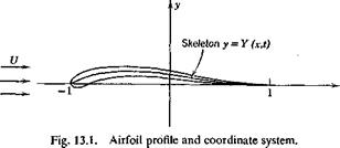
GENERAL EQUATIONS

(See Fig. 13.1.) It is assumed that Y and dY/dx are so small that the skeleton airfoil does not differ appreciably from a horizontal line. The disturbances caused by the motion of the airfoil are therefore small.

The velocity (и, v) of the fluid consists of a uniform mean velocity (U, 0) in the direction of the positive x axis, and a small perturbation (и’, v’):

и = U + г/ (И < U)

(2)

v — v’ (|г/| U)

The acceleration components a’x and a’y are linearized into

diY, ди’ Эи’ ди’ Эu’

; +(C/+C/_

Подпись: (3)Эv’ dv’ ,dv’ dv’ dtf

:_ + (С/+г/)__-_г;__=__+г7_

when small quantities of the second order are neglected. Since the fluid is assumed to be incompressible, p = const; the acceleration potential </>’ is proportional to the change of pressure p’

Подпись:рф’=-Ґ

and is governed by the equation

As shown in § 12.5, there exists a pair of conjugate harmonic functions ф’ and tp’, so that

w = f + jY = f(x + jV) (6)

is an analytic function of a complex variable z = x +jy, and the systems of curves ф'(%, у, t) = const and ip'(x, y, t) = const are orthogonal, w is the complex acceleration potential.

The boundary condition at infinite distance from the airfoil is that u’, v’ -> 0, as shown in § 12.6. That on the airfoil is the tangency of the flow to the solid surface. To express the latter condition mathematically, we may assume that during oscillation every point of the airfoil moves in the vertical direction only. The velocity vector of a point on the airfoil is therefore vx = (0, dY/dt). The velocity vector of the fluid is v2 = (U + n’a, v’a) where the subscript a indicates that the corresponding quantities are evaluated on the airfoil. If we resolve these velocity vectors into directions tangent and normal to the airfoil, then the aforesaid boundary condition is that the normal components of vx and v2 must be equal. Now n = (— 3 Y/dx, 1) is a vector in the direction of the normal; hence, we must have vt • n = v2 • n, or, in terms of the components of these vectors,

ЗУ, rr, ЧЗУ,

— –(U+ua)— + va

Neglecting small quantities of the second order, we obtain the boundary condition

Подпись: (7)£У__ЭУ ЗУ Dt 3 t dx

Подпись: , D2Y *y~~D¥ GENERAL EQUATIONS Подпись: (8)

Similarly, the normal components of the acceleration vectors of the fluid and the airfoil must agree. This leads to the boundary condition

Подпись: 3f Подпись: 3t/ Зі/ 31 dx Подпись: (9)

An acceleration potential ф’ satisfying the boundary condition 8 does not necessarily satisfy the velocity boundary condition 7, which actually amounts to an additional restriction on </>’. To express Eq. 7 in terms of ф’, we have, from Eqs. 3,

For harmonic oscillations we may use the complex representation (§ 1.8) and write

GENERAL EQUATIONS

Then


(И)


GENERAL EQUATIONS

Solving for v, and using the condition v = 0 when x = — oo, we obtain

ф:,у) = т, е-*«*™[Х (12)

U J – со ду

This must be equal to the right-hand side of Eq. 7 on the airfoil.*

In addition to the boundary conditions 7 and 8, the flow must also satisfy the Kutta-Joukowski condition that the velocity be finite at the trailing edge of the airfoil. An equivalent form of this condition is that the pressure (and hence ф) be continuous at the trailing edge of the airfoil.