Category BASIC AERODYNAMICS

Mathematical Approach

The shape and behavior of the Joukowski airfoil are determined by applying an exact mathematical method. The analysis uses the theory of complex variables— in particular, conformal mapping—to map (i. e., transform) a right-circular-cylinder shape (for which the flow with circulation already was determined) in one complex plane into an airfoil shape in a second complex plane. Conformal mapping means that intersecting lines are mapped such that the angles between the lines in the two planes are preserved. To accomplish this mapping, the Joukowski transformation uses a simple transformation function—namely, the first two terms of an infinite series that is the most general transformation formula. This simplicity leads to con­straints on the resulting airfoil geometry.

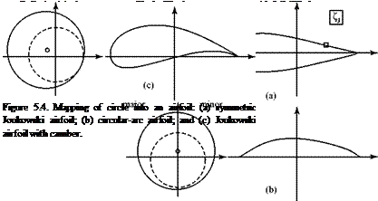
If it is to look like an airfoil, the shape resulting from the transformation must have a rounded leading edge and a sharp trailing edge. To generate a sharp trailing edge by means of the transformation, the circular cylinder (i. e., a circle in the cylinder plane) must pass through one of the critical points of the trans – formation—that is, through a point where the transformation is not conformal. This critical point is located on the x-axis in the circle plane and the center of the cylinder is offset from the origin, being located in the second quadrant of the plane. Figure 5.4 illustrates the geometry of the mapping for several cases of interest. The distance that the center of the circle lies above the x-axis determines the thickness ratio of the airfoil, whereas the distance it lies to the left of the y-axis determines the magnitude of the camber ratio. The cylinder radius is simply a scale factor.

The z (i. e., cylinder) plane is a complex plane in which the cylinder appears as a circle in cross section and a point on the plane is given by the complex variable z = x + iy. Similarly, a point in the q (i. e., circle) plane is described by q = £ + ip. The Joukowski transformation is given by q = z + C2/z = qi + q2, where C is a constant.

Referring to the z (i. e., cylinder) plane in Fig. 5.4, the first term of the Joukowski transformation (qi = z) maps a point-by-point reproduction of the cylinder in the z plane into a “major” circle in the q (i. e., circle) plane. The second term (q2 = C2/z) maps the cylinder in the z-plane into a second (“minor”) circle shown as a dashed line in the circle (q) plane. However, compared to the major circle, the minor circle has a reduced radius, the center of the circle is transformed across the imaginary (i. e., vertical) axis, and a point on the major circle described by the polar angle 0 is reflected in the real (i. e., horizontal) axis as (-0).

Подпись: Run Program JOUK to see how the points on the cylinder map into points on the airfoil in the second complex plane and how the shape of the airfoil is developed. The program also allows the user to compare the shape of a Joukowski airfoil with that of a more familiar airfoil.

Finally, the complete transformation of the cylinder into the qJ (i. e., airfoil) plane is accomplished by the vector addition of two complex quantities, qJ = q1 + q2. One point, z, on the cylinder and its image on the major and minor circles and then on the airfoil surface is illustrated in Fig. 5.4. A complete illustration is found in Program JOUK.
Mathematical Approach

With the geometry established, a function of a complex variable that relates the velocity components on the airfoil to the velocity components on a cylinder at cor­responding mapping points can be determined and then transformed. Because the flow field around a cylinder is known, the velocity (and, hence, the static pressure) on the airfoil can be found at corresponding points. If only the lift is required, finding the circulation around the airfoil provides the answer through the vortex theory of lift.

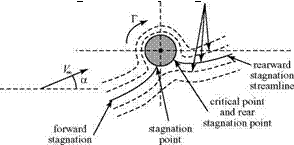
It may be shown that the Joukowski transformation preserves the value of the circulation in the two planes. That is, the circulation around the airfoil is the same as the circulation around the related cylinder, and the lift force on the airfoil follows from the Kutta-Joukowski Theorem once the circulation is known. How is the unique value of the circulation around the cylinder established? Recall that the critical point on the cylinder transforms into the airfoil trailing edge. Now, to satisfy the Kutta condition, the trailing edge of the airfoil must be a stagnation point. This means that the critical point in the circle plane also must be a stagnation point, as shown in Fig. 5.5.

Once the freestream flow direction, a, is selected (which is also the airfoil angle of attack) and the location of the center of the cylinder is chosen, the magnitude of the circulation required to hold the rear stagnation point on the cylinder at the critical point can be calculated. The lift per unit span, L’, on the corresponding Joukowski airfoil follows directly. Inviscid theory predicts that the drag of the Joukowski air­foil is zero in accordance with the D’Alembert’s Paradox discussed previously.
Подпись: Figure 5.5. Flow around a cylinder linked to flow around a Joukowski airfoil. Mathematical Approach

Mathematically, this is because the flow is symmetrical about this cylinder relative to a line through the center and perpendicular to the freestream flow direction.

Results

Подпись: Ci = Mathematical Approach

Recall the definition of the two-dimensional lift coefficient:

The result for a symmetrical Joukowski airfoil at moderate angle of attack is:

Ce = 2 n(1 + e)a,

Mathematical Approach Подпись: (5.l)

where a is the geometric angle of attack of the airfoil (i. e., the angle between the freestream direction and the airfoil chord line) and e is a small number proportional to the thickness ratio. For a vanishingly thin (e ^ 0) symmetric Joukowski airfoil, the lift curve slope is:

For a 10 percent-thick Joukowski airfoil, the theoretical lift-curve slope is only about 7 percent higher. Remember that these results are exact; they suggest that if an airfoil is thin (i. e., less than 10 percent), then the effect of the thickness ratio on the lift-curve slope can be ignored with minor error. Keep this in mind when the assumptions involved in the thin-airfoil theory are presented herein.

Unfortunately, the Joukowski transformation leads to an airfoil shape that is not practical based on experience. The mean camber line is always a circular arc regardless of which airfoil camber and thickness ratios are chosen, and the maximum thickness of the Joukowski airfoil is always at about the quarter-chord—which, in practice, is too far forward. Finally, the trailing-edge angle is always a cusp (i. e., has a zero-included angle). It is possible to generalize the Joukowski airfoil shape to incorporate a finite trailing-edge angle by taking more terms in the general trans­formation formula; however, the method becomes complicated even for symmetrical airfoils.

The Joukowski airfoils were used in the 1930s in Europe in several sailplane designs. They formed the basis of the successful Gottingen series of airfoils that are used in the present day in low-speed designs. Preceding World War II, they were considered state-of-the-art for high-performance sailplane applications. Even if the Joukowski airfoil is not currently considered to represent a practical airfoil-design approach, it has a role in modern analysis because the pressure distribution and lift results are based on a rigorous theory with no approximations. The complex variable analysis thus provides useful benchmark results against which to compare numerical or approximate solutions.

Numerical-analysis methods for inviscid flow were developed that are, in a sense, the inverse of the approach described previously. In these methods, an arbitrary air­foil shape is selected (including a finite trailing-edge angle) and then is transformed into a circle. The flow field for the circle (cylinder) is solved and this solution is trans­formed back to the airfoil plane, yielding the velocity distribution (and, hence, the pressure distribution) on the airfoil. However, numerical-panel methods (discussed herein) are preferred for solving this problem.

Finally, although the conformal-mapping approach and the underlying complex – variable theory now are not used directly in the solution of practical aerodynamics problems, the ideas involved are of interest in the sense described. If students are interested in more details on the application of conformal-mapping methods, they should consult the extensive literature on the subject published previously in the 1930s (cf. Glauert, 1926/1947).

Two-Dimensional Airfoil Behavior

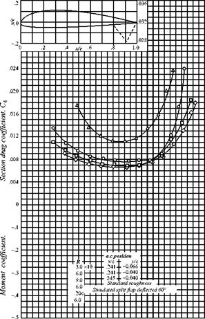
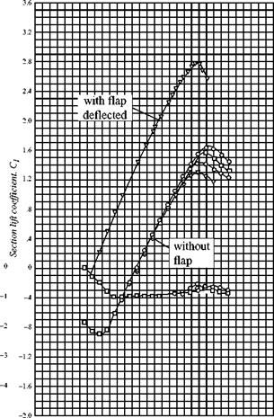
Figure 5.3 shows the behavior of a typical cambered, two-dimensional airfoil as a function of geometric angle of attack (i. e., the angle between the freestream and the chord line). The data presented in this figure, and other similar figures, are from experiments. The nomenclature that specifies the shape of the airfoil illustrated in this figure is defined later. In Fig. 5.3(a), notice that up to an angle of attack of about 10 degrees, the lift increases linearly with angle of attack. Above 10 degrees, the lift begins to drop off and, at about 16 degrees (depending on the Reynolds number), the loss in lift is catastrophic; that is, the airfoil stalls. The upper lift curve shows the

Подпись: 172 Two-Dimensional Airfoils

Two-Dimensional Airfoil Behavior

-1.2 -.8 -.4 0 .4 .8 1.2 1.6

Section lift coefficient, c1 NACA 4415 Wing Section (Continued)


Подпись: Moment coefficient,

-32 -24 -16 -8 0 8 16 24 32

Section angle of attack, a, deg NACA 4415 Wing Section (a) Lift and moment


(b) Drag


Figure 5.3. Two-dimensional airfoil behavior (NACA 4415, (Abbott and Van Doenhoff, 1959)).


Two-Dimensional Airfoil Behavior

effect of a deflected flap. The lift curve does not maintain a constant slope because viscous effects begin to dominate. As the angle of attack increases, the adverse pressure gradient over the aft-upper surface of the airfoil becomes larger and the boundary-layer separation point begins to move upstream from near the trailing edge. As a result, a loss in lift occurs over the rear portion of the airfoil. Suddenly, the separation point jumps to near the leading edge, the aerodynamic shape as “seen” by the flow changes dramatically, and the airfoil stalls. The maximum lift coefficient, Qmax, is obtained immediately before the stall. Notice how Q max for the airfoil depends on the Reynolds number (Re), which indicates that the airfoil boundary – layer behavior is varying with the Reynolds number. Of course, the inviscid theory considered here predicts neither stall nor Q max; rather, it predicts the lift curve slope for moderate angles of attack.

Figure 5.3(a) shows that at zero lift, the angle of attack for this airfoil is negative because the airfoil has positive camber. The negative angle of attack required for zero lift is called the angle of zero lift. If the airfoil is symmetric, the angle of zero lift is zero.

The pitching-moment coefficient also is shown in Fig. 5.3(a). Here, it is taken about the aerodynamic center, which is that point on the airfoil about which the pitching moment is independent of angle of attack. Do not confuse this with the center of pressure, which is the point about which the total moment is zero. The location of the aerodynamic center and the moment about the aerodynamic center can be found from testing and also predicted from inviscid theory (for moderate angles of attack). Because the pitching moment is defined as positive clockwise (i. e., nose up), the negative pitching-moment coefficient shown in Fig. 5.3(a) implies a nose-down (i. e., counterclockwise) sense and, hence, a restoring (i. e., stable) moment.

Fig. 5.3(b) shows experimental data expressing the drag behavior of the same airfoil. This curve, called the drag polar, presents drag coefficient versus lift coefficient rather than drag coefficient versus angle of attack. The drag in these two-dimensional tests is called the profile drag. This is the part of the drag due to the action of viscosity. It is the sum of two drag contributions—namely, skin-friction drag and pressure drag due to flow separation. Notice how the drag increases dra­matically as boundary-layer separation begins to dominate the flow field. Airfoil drag is predicted to be zero for two-dimensional inviscid flow. The subject of drag appears in many places in the text because it originates in several ways. Detailed discussions are in Chapter 9, in which the subject of compressible wave drag is set forth.

5.2 The Joukowski Airfoil

To illustrate what can be accomplished with an analytical technique, we consider representing an airfoil as a mapping of a known flow solution. In particular, we con­sider the circular cylinder with a superposed vortex flow studied in Chapter 4. This model was used to demonstrate the connection between lift and the creation of circulation. If we could distort the coordinates correctly, perhaps we could use this known solution to understand the flow around actual airfoils.

Airfoil-Shape Parameters

An airfoil shape is usually perceived as a symmetric thickness envelope distributed above and below a mean camber line (camber is a measure of the curvature of an

Airfoil-Shape Parameters

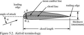
airfoil). The chord line is a straight line joining the two ends of the mean camber line, which are termed the leading edge and the trailing edge and are depicted in Fig. 5.2.

Strictly speaking, the thickness envelope is defined as measured along a line per­pendicular to the mean camber line (e. g., A-A). However, if the maximum camber is small, then the thickness distribution may be defined as symmetrical above and below the mean camber line as measured in a direction perpendicular to the chord (e. g., B-B). For small camber, the difference between A-A and B-B is minor. Following are the major parameters that define an airfoil shape:

1. Camber (curvature): The shape of the mean line of the airfoil. This shape is usually expressed in terms of camber distribution (i. e., distance to the chord line as a function of chord length) and camber ratio (i. e., maximum camber as a percentage of chord).

2. Thickness: Usually expressed in terms of thickness distribution (i. e., the height of the airfoil relative to the mean camber line approximately the chord line, as a function of chord length) and thickness ratio (e. g., the maximum thickness of the airfoil expressed as a percentage of chord).

3. Nose radius: (radius of a circle fitted to the nose).

4. Slope of the airfoil at the trailing edge: (angle between the camber line and chord line at the trailing edge).

Expressing maximum camber and maximum thickness as a ratio with the chord is convenient because an airfoil of given camber and thickness can appear to the flow as a large or a small obstacle, depending on the relative magnitude of the chord. It follows from these definitions that a symmetrical airfoil has zero camber, with the thickness distributed symmetrically about the chord line.

Two-Dimensional Airfoils

5.1 Подпись: 5Introduction

A flight vehicle is sustained in the air by the lift that is generated on the wings. If the vehicle design is to be successful, this lift must be generated as efficiently as possible—that is, with minimum drag and structural weight. Because of their enor­mous importance, wings (and the airfoil sections that comprise them) have been studied for years both experimentally and analytically. The emphasis in this chapter is on flow about airfoil shapes in two dimensions. Two-dimensional flow implies that the flow field and the body shape are identical in any vertical plane aligned with the flow. Thus, an airfoil section at any spanwise station of an infinite wing of constant section (Fig. 5.1a) behaves as if it were in two-dimensional flow (Fig. 5.1b).

Two-Dimensional Airfoils

If a lifting wing has a finite span band, hence, wing tips at values of,

Two-Dimensional Airfoils Подпись: x

then there is a flow around the wing tips from the lower surface (i. e., higher pressure) to the upper surface (i. e., lower pressure). The intensity of the spanwise flow due to this effect varies across the wing span, so that the flow field is no longer the same at every spanwise (y) station. The finite wing, therefore, constitutes a three-dimensional flow problem (see Chapter 6).

The focus of this chapter is the prediction of the pressure distribution, lift forces, and moments on various airfoil shapes as well as the dependence of these quantities on airfoil-shape parameters. Initially, no viscous forces are accounted for explicitly; therefore, no drag occurs on a two-dimensional shape. This result is known as D’Alembert’s Paradox, and its origin can be identified readily in the cal­culations in Chapter 4 that describe the lift generation on a cylinder with circulation. Modification of the pressure distribution by three-dimensional flow effects and by viscous forces leads inevitably to drag.

Airfoil shapes are defined by mathematical techniques or by prescribing the values of the shape parameters. The emphasis then is on the so-called direct problem. That is, given the airfoil shape, we find the pressure distribution and the force and moment behavior of the airfoil with angle of attack. The direct problem is investi­gated by experiment, by exact or approximate theories, and—in recent years—by numerical analysis.

Recently, the inverse problem has received considerable attention. That is, given the desired chordwise pressure distribution, we find the airfoil shape that leads to this distribution. The motivation for this approach is control of the behavior of the boundary layer on the airfoil surface relative to transition and separation. Stream – wise pressure gradients have a major effect on the growth and stability of a viscous boundary layer. This suggests that it is desirable to specify the chordwise pressure distribution on the airfoil and then find the airfoil geometry that would generate this pressure distribution. Thus, the airfoil shape is compatible with the desired boundary-layer development. This method allows significant decreases in drag and optimization of other airfoil characteristics. Numerical analysis provides a powerful technique for solving this type of problem; hence, computational methods now have a major role in modern airfoil design.

It is not possible to cover here, in detail, all of the many approaches used in the analysis of airfoils; rather, the objective is to provide a strong framework within which the student readily can access particular techniques in later study. Therefore, the chapter is organized as follows: First, airfoil shape and behavior parameters are defined. Then, the primary focus is to solve the direct problem of determining pressure distribution, forces, and moments on a specified airfoil shape. This development begins with an example of a classical technique for determining the shape and per­formance of an airfoil of arbitrary thickness ratio by an analytical method. Following this, the experimental performance assessments carried out by the National Advisory Committee for Aeronautics (NACA; now NASA) using systematic shape variations are explained. Next, thin-airfoil theory is developed for the prediction of forces and moments on airfoils of arbitrary (but thin) shapes. Thin-airfoil theory is considered in detail because this analysis provides excellent insight into the role of airfoil param­eters and geometry on their aerodynamic performance. The chapter concludes with a brief discussion of numerical methods as applied to the direct problem, as well as comments on modern approaches to the inverse problem with sample results.

The Starting Vortex: Kelvin’s Theorem

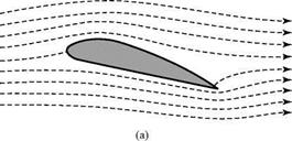
The existence of circulation around an airfoil may be confirmed by using an inviscid – flow model and Kelvin’s Theorem.[21] The argument is based on the experimental evi­dence of a starting vortex at the trailing edge of an airfoil.

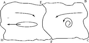
Consider a large closed path, A-B-C-D, enclosing a fixed airfoil in a flow at rest. The circulation around this closed path is zero because the velocity is zero every­where. Assume that the fluid particles comprising this path were marked in some way and then impulsively set the flow in motion from rest. Kelvin’s Theorem states that for an inviscid flow, the time rate of change of circulation around a closed path comprised of the same fluid particles is zero. That is: in Eulerian derivative notation. This means that the circulation that was initially zero around the original closed path, A-B-C-D, must continue to be zero even when the closed path is swept downstream because A-B-C-D always is assumed to be described by the same fluid particles.

Now, assume that the flow continues at a constant velocity and that a starting vortex was formed and shed. Let the time interval dt be short enough and the closed path be large enough so that both the airfoil and the shed vortex are contained within A-B-C-D, as shown in the snapshot taken at t = dt (Fig. 4.17). Remember that the circulation around this closed path is still zero.

The Starting Vortex: Kelvin’s Theorem

Figure 4.17. The starting vortex.

Now, subdivide the original closed path, A-B-C-D, into two parts by adding an arbi­trary line, E-F, located somewhere between the airfoil and the shed vortex. Around the closed path E-B-C-F, there is a nonzero value of circulation because the path encloses a vortex. However, this means that an equal and opposite circulation must exist around A-E-F-D because the sum of the two must cancel to satisfy Kelvin’s Theorem. Because the starting vortex was formed when the flow along the lower surface of the airfoil tried to go around the trailing edge and then separated, the sense of the starting vortex is counterclockwise for positive lift. The conclusions, then, are that a circulation must be present around the airfoil, it must have a unique value, and it must have a clockwise sense.

4.7 Summary

In this chapter, we introduce techniques for solving aerodynamics problems involving incompressible, inviscid flow fields. We demonstrate that under these con­ditions, the governing equations reduce to the Laplace’s Equation, which has been studied extensively in many fields. Because it is a linear differential equation, its simplest solutions can be superimposed to produce more complex flows. We carry out solutions for four cases that we identify as the uniform flow, the simple source (or sink), the vortex, and the doublet. Superposition of a uniform freestream with a doublet and a vortex yields a solution that we identify as the flow around a spinning cylinder. Of great significance in this example is the creation of lift. This enables us to search for the fluid-dynamics origin of the lifting force, which we identify as the generation of a circulatory flow around the moving body. This idea is extended in the form of the Kutta-Joukouski Theorem to represent the lift on bodies of arbitrary shape. The need for a sharp trailing edge in creating lift on an airfoil is discussed, and the results are summarized in the so-called Kutta condition.

The Kutta Condition

In the lifting-cylinder case discussed in Section 4.7, the value of the circulation gen­erated in the spinning-cylinder experiment (and, hence, the lift on the cylinder) is arbitrary. The circulation depends on an external input: the rate of spin of the cylinder. Because the Kutta-Joukouski Theorem states that the lift on an airfoil is proportional to the circulation and because from experience the lift on a particular airfoil is unique for a given orientation, there must be a physical mechanism (not an external input) that specifies a unique value of the circulation about an airfoil. The flow condition to be satisfied that results in the generation of a unique value of the circulation about a lifting airfoil is called the Kutta condition. It is stated formally herein, but first the physical phenomena that establish this condition are explained by introducing viscosity into the flow model. When the flow phenomena are dis­cussed, the viscosity switch is turned “off” again and the physical behavior observed in nature is suitably incorporated into the inviscid-flow model.

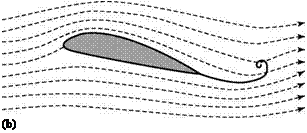
To visualize the following discussion, consider a thought experiment. A two­dimensional airfoil is set at a positive angle of attack in a viscous (real) medium at rest, as illustrated in Fig. 4.16.

The Kutta Condition

The flow is started in motion to the right and rapidly brought up to a constant velocity. At the first instant of time, the flow next to the lower surface of the airfoil proceeds toward the sharp trailing edge and then around the trailing edge to the upper surface, as if there were no viscosity present. That is, the flow is essentially a potential

Подпись: (b) Figure 4.16. Airfoil started impulsively.

flow at the initial instant (Fig. 4.16a). As a consequence, this stream tube exhibits a sharp reversal of direction with zero radius of curvature right at the sharp trailing edge. This means that the velocity at the trailing edge at that instant is infinite. An infinite velocity is a physical impossibility. Because the viscous fluid cannot accom­modate this zero-radius turn, it instantaneously separates at the trailing edge and rolls up into a vortex with a counterclockwise sense (Fig. 4.16b). As the freestream velocity continues to increase rapidly, approaching a constant value, the fluid at the trailing edge continues to separate and roll up so that the instantaneous vortex grows and becomes stronger. The flow field responds to this strengthening vortex (increasing vorticity) at the trailing edge by setting up a reaction effect (circulation) about the air­foil. As a consequence, the upper-surface stagnation point, which was instantaneously located well upstream of the trailing edge, moves rapidly toward the trailing edge. Finally, when the freestream velocity reaches a constant value, the flow along the air­foil upper surface smoothly leaves the trailing edge and the fluid particles comprising the so-called starting vortex roll up tightly and are swept downstream. This starting vortex need not be included in a steady-flow problem, where the flow is considered to have been going on for a long time. The reason is that the starting vortex is located far downstream of the airfoil in such a problem and its influence at the airfoil is negligible because the velocity field associated with a vortex varies inversely with the distance.

If the airfoil angle of attack is sharply increased in a constant-velocity flow, another vortex of the same sense described previously is formed and sheds down­stream. If the angle of attack of the airfoil is suddenly decreased, a vortex of the opposite sense rolls up and sheds. The strength of the circulation around the airfoil likewise changes to a unique value as the airfoil angle of attack is changed. The experimentally observed fact, then, is that the viscous shear layer on the airfoil sur­face first rolls up at the trailing edge and then the flow field adjusts until this rollup no longer occurs. Each flow adjustment generates a unique value of circulation about the airfoil (see Section 4.10).

Formally, the Kutta condition states that a body with a sharp trailing edge gener­ates a circulation of just sufficient strength that the flow smoothly leaves the trailing edge. The Kutta condition has a vital role in the inviscid thin-airfoil theory devel­oped in Chapter 5 because it serves as a boundary condition.

Now, the statement that the flow smoothly leaves the trailing edge must be stated more carefully because there are two possibilities, as follows:

1. Finite trailing-edge angle.

The Kutta Condition

In this case, the two velocity vectors at the trailing edge are parallel to the upper and lower surfaces. In the limit, right at the trailing edge, this implies that there are two flows going in two different directions at the same point, which is physi­cally impossible. The situation is resolved if both velocities at the trailing edge are zero (i. e., then, they have no flow direction). Accordingly, the trailing edge must be a stagnation point and the circulation must be of precisely the right
magnitude so as to move the stagnation point, which was initially on the upper surface of the lifting airfoil, downstream to the trailing edge.

The Kutta Condition
The Kutta Condition

2. Cusped trailing edge.

Here, there is no conflict in flow direction. However, the velocity magnitudes (upper and lower) must be identical because, otherwise, the Bernoulli Equation demands that there be a static-pressure difference between the upper and lower surface flows as they leave the trailing edge. However, between the two flows right at the trailing edge, there is a free surface (i. e., interface) that cannot sup­port a pressure difference. The conclusion is that the two velocities at the trailing edge must be the same, and a circulation is set up around the airfoil so as to make this happen. A cusped trailing edge on an airfoil is not a practical configur­ation because it requires an infinitesimal thickness. However, airfoil designers strive to come as close to this ideal configuration as possible while recalling the practical limitations imposed by structural considerations.

The Kutta-Joukouski Theorem

It is shown in Section 4.7 that an integration of the pressure distribution on a lifting cylinder leads to the result that the lift per unit span is proportional to the circu­lation around that cylinder. The Kutta-Joukouski Theorem[20] states that for any body of arbitrary cross section (e. g., an airfoil), the lift per unit span L’ = рУмГ, where Г is taken around any closed path enclosing the body. The proof of the theorem is beyond the scope of this book. However, the theorem was demonstrated to be true for a right circular cylinder by integration of the static pressure acting on the surface of a body, and it is shown later to be true for an airfoil shape.

The importance of this theorem is that it provides an alternative way to calcu­late the lift force on a lifting body. Instead of calculating the velocity magnitude at a point on the body surface, then using the Bernoulli Equation to evaluate the pressure there, and finally integrating to determine the force, the theorem states that the lift force can be found simply by calculating the circulation around the body. As previously mentioned, it often is easier to calculate the circulation than it is to deter­mine the pressure distribution. Of course, if the pressure magnitude at a point or the pressure distribution on the body surface is required, the theorem is of no help because it speaks only of the net force.

This theorem is the basis for the so-called circulation theory of lift. This is a math­ematical method of calculating lift that convenient for many inviscid-flow problems. However, remember that the lift (and drag) on a body is physically generated by the pressure (and shear-stress) distribution over the surface. The oncoming flow adjusts to accommodate the presence of the lifting body and, in so doing, sets up a velocity and pressure field such that the circulation around the lifting body is nonzero.

To fix ideas regarding lift and circulation, imagine a two-dimensional wing installed at an angle of attack in a wind tunnel. Also imagine that there is a suitable instrument available that measures the flow velocity (i. e., magnitude and direction) at numerous points around the wing. The particular points of interest are located along a closed path in a vertical plane aligned with the oncoming stream. Make the measurement, form the vector-dot product V • ds at each measurement station, and sum around the closed path. This calculation of circulation yields a positive quantity that is equal to L7pVTO. Thus, the lift (i. e., physically, the net pressure force acting upward on the wing) is exhibited as a circulation around the wing. Recall an ana­logy in Chapter 3 in which a measurement of drag was carried out by evaluating the momentum loss in the wake. There, the drag was due physically to the pressure and
shear forces acting on the body surface and the drag was exhibited as a momentum loss.

Remember that the presence of a circulation around a body does not imply any fluid particles rotating about it. It simply means that the flow above and below the lifting body is higher and lower average velocities than the zero-lift value, respectively.

Uniform Flow Plus Doublet Plus Vortex: Flow Around a Lifting Cylinder

The superposition of a uniform flow and a doublet yielded a useful body shape (i. e., a cylinder), but the flow field was symmetrical so that there was no net force on the cylinder. The addition of a vortex in the superposition creates an asymmetry in the flow. In particular, if the vortex is at the origin and has a clockwise sense, then it adds to the local velocity over the top half of the cylinder and subtracts from it over the bottom half. This asymmetry in the velocity field leads to an asymmetry in static pressure. From the Bernoulli Equation, the lower values of static pressure are on top of the cylinder and the higher values of static pressure are on the bottom of the cylinder. When integrated, this pressure asymmetry leads to a net force upward— that is, to a positive lift. Because no asymmetry is introduced about the у-axis by the superposition of the vortex at the origin, there is no unbalanced force in the x-direction. Thus, the drag of the cylinder is still zero.

Recall that in the development of Eq. 4.34 for the vortex, the constant of inte­gration in the stream-function expression arbitrarily was set equal to zero for con­venience. However, this constant may have any value because the velocity field is obtained by differentiation and the constant disappears. In this superposition to obtain the flow over a lifting cylinder, we write the constant of integration as the constant:

-—lnR

instead of setting the constant equal to zero.

Подпись: у V = -і-ln r + const = -Гln r —— ln R = i- In r

The stream function for the vortex to replace Eq. 4.34 then becomes:

Uniform Flow Plus Doublet Plus Vortex: Flow Around a Lifting Cylinder Подпись: (4.45)

The constant of integration was changed so that at r = R, yv = 0. Thus, the zero streamline for the vortex now is on the circle r = R, just as it is for the superposition of a doublet with a uniform flow. Then,

The student should verify by substitution that the stream-function expression given by Eq. 4.45 is indeed a solution to the Laplace’s Equation. The streamlines resulting

from the superposition in Eq. 4.41 are seen by running Program PSI. Notice with respect to this program that:

1. Подпись:There are two parameters to vary: the freestream velocity and the strength of the vortex. Note what happens when these are varied. In particular, hold the freestream velocity constant and vary the vortex strength.

2. Although the streamline у = 0 still lies on the circle r = R, it no longer lies along the x-axis away from the cylinder. In particular, from Eq. 4.45, along the stream­line у = 0:

Г lnX

sine =—– 2n R n,

Vr 1 – 4

Now, for Г > 0 (i. e., for a clockwise vortex according to the sign convention estab­lished previously), this expression states that if r is greater than R, then sin Є < 0, which places the zero streamline in the 3rd and 4th quadrants and not along the x-axis, as was the case for the nonlifting cylinder. Thus, as expected, the flow field is not symmetrical about the x-axis.

Подпись: 1 dy T/ Q ur = -—;- = V cose r de Подпись: 1 - A Подпись: (4.46)

Next, we examine the velocity field:

Подпись: Г 2nr ue = -^y = – V sin Є

e de “

Eq. 4.46 shows that the radial component of velocity is zero on the surface of the cylinder, r = R, so that the “no-flow-through” boundary condition still is satisfied. The boundary condition far from the body (i. e., for very large r) also is satisfied because far away from the body:

ur ^ V cose and ue ^ V sine so that ur[18] [19] + u2e ^ V2^

and the disturbance due to the body dies out. Finally, if we go back to the velocity – component equations for the three fundamental solutions that comprise this super­position, it is shown that the superposition represented by the new stream function in Eq. 4.45 also implies an addition of the three constituent velocity components at any point (Eq. 4.46). This fact can be useful.

Next, examine the asymmetry of the flow by locating the stagnation points on the cylinder. Again, refer to the computer solution represented by Program PSI and vary the vortex strength. Recall the condition for a stagnation point to exist— namely, that ur = ue = 0. From Eq. 4.46, ur = 0 when r = R (the cylinder surface) or when e = n/2 or 3n/2. Examine each of the following three possibilities:

Because the sine function is bounded between ± 1.0, this states that Г < 14kRV The zero value of circulation corresponds to the stagnation points on the x-axis (i. e., nonlifting case). Confirm this result by running the program.

2. If ur = 0 by virtue of 0 = n/2 and we demand that u0 = 0 there as well, then from Eq. 4.46, it follows that for a positive r, the circulation must be negative. Ignore this choice because it was shown that positive (i. e., clockwise) circulation pro­vides positive lift.

3. If ur = 0 because 0 = 3n/2, then if u0 = 0 as well, it follows from Eq. 4.46 that:

Подпись: і R2 1+-Uniform Flow Plus Doublet Plus Vortex: Flow Around a Lifting CylinderV

Подпись: r R Uniform Flow Plus Doublet Plus Vortex: Flow Around a Lifting Cylinder Подпись: -1,

Solving this quadratic equation for r/R:

which is valid only if ——- > 10.

4nRVM

Now, recall from Condition (1) that if the stagnation point is on the surface of the cylinder, then Г < !4kRV! tc. Thus, the stagnation point in Condition (3) corres­ponds to a stagnation point along the negative y-axis (directly below the cylinder) and is either on or away from the surface (i. e., in the external flow field). We observe this by running the program.

Finally, we run Program PSI and take note of the pressure (and pressure – coefficient) distribution around the cylinder. The distributions are not symmetrical with respect to the x-axis and there is a resulting unbalanced (lift) force. The magni­tude of this force is determined later by integrating the pressure distribution. The pressure-coefficient information in this program is presented with positive values of the coefficient along the positive ordinate to emphasize the physical situation; how­ever, this is not the usual format for presenting airfoil pressure-coefficient information.

Does this superposition of a uniform flow, a doublet, and a vortex correspond to a physically realistic flow situation? As in the case of the nonlifting cylinder, the drag of the lifting cylinder is zero by virtue of the symmetry of the flow field about the y-axis. In this respect, the superposition is not realistic. However, it is physically possible to generate an unbalanced force on a symmetrical geometric object such as a cylinder. To understand this, the role of viscosity must be recognized. If we set up an experiment and rotate a cylinder in a clockwise direction in a uniform flow, then the large viscous-shearing action at the surface of this cylinder diffuses into the flow and tends to “pull” the flow along on the upper side and “retard” the flow on the lower side. (To visualize this, imagine rotating a cylinder in a flow of oil.) This viscous action creates a flow asymmetry that manifests as an unbalanced force on the cylinder. There is a circulation set up around the body by virtue of the viscous shear, or vorticity, at the surface; this circulation is represented by the vortex in the inviscid model. Notice that the presence of circulation does not imply that there are any circular streamlines around the cylinder.

As we would expect, the magnitude of the unbalanced force on the spinning cylinder is proportional to the rate of spin, which is an external input. There is no physical mechanism here to specify the magnitude of the spin and, hence, of the circulation. It is shown later that in the case of a sharp-edged body such as an airfoil, there is a physical mechanism present that selects a unique value of circulation for each angle of attack. Again, to explain the presence of this mechanism, it is necessary to appeal to experiment and to the role of viscosity.

Next, the force on a lifting cylinder is evaluated by integrating the surface pressure over the cylinder surface. The force in the lift (y) direction is sought. The drag (x)-direction force can be argued to be zero by symmetry or proven to be zero by integrating the net surface-pressure force in the x-direction.

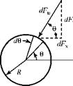
From Fig. 4.15, dFn is the normal force due to a pressure p (force per unit area) acting on an element of surface area Rd0 of the two-dimensional circular cylinder. Notice that the length of the element normal to the x-y plane is taken to be unity; the calculation then gives the force per unit length of the cylinder. Resolving this force into components in the coordinate directions:

dFx = – dFncos0 = – pRcos0d0. dFy = – dFnsin0 = – pRsin0d0.

Now, we sum these differential component forces by integration over the entire cyl­inder, recalling that V = V(0) is known so that the pressure can be expressed from the Bernoulli Equation as p = p(0). The evaluation of Fx is left to the student as an exercise. Fy is found to be:

2п 2П П/2

Fy = J dFy=- J pR sin0d0 = -2R J psin0d0,

0 0 – n/2

where the limits of integration are replaced by observing the symmetry about the y-axis.

From the Bernoulli Equation, p = po – 1/2pV2. Thus,

Подпись: Fy=-Uniform Flow Plus Doublet Plus Vortex: Flow Around a Lifting Cylindern/2 n/2

sm 0d0= 2Rp0 J sin0d0+pR J V2sin0d0.

-n/2 – n/2

The first integral is zero by virtue of the integration of the sine function between the limits. Now, on the surface of a cylinder with circulation:

Г

V = u0=-2V sin0——— ,

0 “ 2nR

Подпись:Uniform Flow Plus Doublet Plus Vortex: Flow Around a Lifting Cylindery.

Подпись: п/2 г Подпись: (A) Подпись: -,2 Подпись: (B) Uniform Flow Plus Doublet Plus Vortex: Flow Around a Lifting Cylinder

because ur = 0. Thus,

Uniform Flow Plus Doublet Plus Vortex: Flow Around a Lifting Cylinder

The circulation and the freestream velocity are constants independent of 0. Hence, terms (A) and (C) integrate to zero between the limits, and the integral of sin20 in term (B) is n/2. Therefore:

or

Uniform Flow Plus Doublet Plus Vortex: Flow Around a Lifting Cylinder(4.47)

where L’ is the lift on the cylinder (i. e., the force acting perpendicular to the freestream direction) per unit length of cylinder. The “prime” here denotes per unit length or per unit span.

Evaluating Fy in Eq. 4.47 entails using superposition to find a stream function, differentiating this function to determine velocity components, using the Bernoulli Equation to determine the pressure distribution on the cylinder, and integrating the pressure distribution to find the lift force. The final result is interesting; it shows that the lift per unit span is proportional to the circulation about the cylinder. If this were a general result, Eq. 4.47 indicates that we can evaluate the lift on a body by finding the circulation about the body; it is not necessary first to find the pressure distribution and then to integrate. This is an attractive idea because it is often easier to find the circulation about a body than it is to find the pressure distribution on the body surface and then integrate (e. g., in the thin-airfoil theory in Chapter 5). As shown in the next section, this is indeed a general result and Eq. 4.47 holds for any right cylinder (e. g., an airfoil), not only a right-circular cylinder.

Note that in Eq. 4.47, the magnitude of the circulation is arbitrary. There is nothing inherent in the flow field that determines it. Thus, the lift on the cylinder can have any value depending on the magnitude of the circulation (i. e., the magnitude of the spin that is given to the cylinder in an experiment). As discussed later, if a body in a uniform flow has a sharp edge (e. g., an airfoil with a sharp trailing edge), then the resulting flow field specifies the magnitude of the circulation about the body for any body attitude. The resulting lift force that is generated has a unique value.

EXAMPLE 4.12 Given: A lifting cylinder of radius 2 feet is experiencing a lift force of 8 pounds per foot in a freestream with a velocity of 20 ft/s. Assume steady, incompressible, inviscid flow at standard conditions.

Required: (a) What is the circulation about this cylinder? (b) Where are the stag­nation points located on the cylinder? (c) What is the maximum velocity on the surface of the cylinder? (d) What is the value of the pressure coefficient on the bottom of the cylinder?

Approach: Eqs. 4.46 and 4.47 yield the circulation strength and give velocity information. Eqs. 4.46 and 4.28 are needed for the pressure-coefficient part of the question.

Solution:

(a) From Eq. 4.47:

L’ = 8.0 = p VT = (0.002378)(20)Г ^ Г = 168ft2/s

(b)

Подпись: ue = 0 = -V sin Є Uniform Flow Plus Doublet Plus Vortex: Flow Around a Lifting Cylinder Подпись: Г 2nR Подпись: (20) sin Є [2] Подпись: 168 2n(2).

On the cylinder surface, ur = 0 and, at the stagnation points, ue also is zero. Then, from Eq. 4.46:

Solving for Є and recognizing that the stagnation points are in the third and fourth quadrants, Є = 199.5° and Є = 340.5°.

(c) The maximum velocity is at the top of the cylinder. There, Є = n/2 and Eq. 4.46 yields a value for the tangential velocity of -53.4 ft/s; the negative sign indi­cates flow in the downstream direction.

(d) At the bottom of the cylinder, Є = 3n/2. From Eq. 4.46, ue = V = 26.6 ft/s (the positive sign now indicates the downstream direction), and from the pressure coefficient expression, Eq. 4.28:

V2

Cp = 1 – – Цг = -0.77. p V 2

Appraisal: (a) Check the units of Eq. 4.47 and confirm that circulation has the units ft2/s. Verify this by realizing that circulation is the line integral (summa­tion) of the product of a velocity and a line segment; hence, it should have the units [ft/s][ft].

(b) The locations of the stagnation points are as expected: They are symmetrical about the y axis.

(c) The velocity at the top of a nonlifting cylinder is twice the freestream value. Here, the velocity at that location is about 2.5 times the freestream value. This indicates the additive effect of the clockwise vortex and, from the Bernoulli Equation, implies that the static pressure at that point is less than it would be for the nonlifting case.

(d) The velocity at the bottom of the lifting cylinder (26.6 ft/s) is less than the value for the nonlifting cylinder (40 ft/s), indicating that at that point, the clock­wise vortex is opposing the oncoming stream. However, note that this velocity

is still greater than the oncoming freestream value (20 ft/s) so that the flow is retarded but not reversed. The same conclusion can be drawn from the negative sign on the value of the pressure coefficient at the bottom of the lifting cylinder. There is a local acceleration of the freestream flow at that point, but it is less of an acceleration than in the nonlifting case. When a stagnation point occurs on the bottom of the cylinder, the influence of the circulation is just sufficient to oppose the local flow in the downstream direction and bring it to rest.

Uniform Flow Plus Source-Sink Pair

As surmised from the preceding section, the superposition of a sink located down­stream of the source discussed yields the flow around a closed body—that is, pro­viding that the source and sink are of equal strength (i. e., net strength of zero indicating that the mass emanating from the source is absorbed by the sink). Thus, using Eqs. 4.30 and 4.31:

V = Vuf + V S1- V S2 = V~r sin 0 + 2П01-2n 02 , (440)

where 0 is the polar angle to the point in question and 01 and 02 are the angles between the positive x axis and straight lines joining the source-sink (respectively) and the point in question. By holding V and Л fixed and assigning different constant values to the stream function in Eq. 4.40, we can find different combinations of r, 0, 01,and 02 that satisfy this equation (i. e., 01 and 02 can be expressed in terms of r and 0 for a specified spacing between the source and sink). Then, the streamlines may be found by plotting curves, which are generated by varying the angle 0 and using Eq. 4.40 to solve for the radius r for a particular streamline corresponding to a constant value of v. Each value of v provides another streamline. The result of joining the dots is demonstrated in Program PSI.

RUNNING PROGRAM PSI

1. One streamline represents a closed body, as expected. Confirm that the body shape and size depends on the values of freestream velocity, source-sink strength, and source-sink spacing.

2. The body has two stagnation points, one at the front and the other at the rear. Their locations may be found by solving for u and v and setting both velocity components equal to zero. From this, the value of the stream function on this stagnation streamline follows.

3. The velocity singularities are located within the solid body.

4. The body shape looks like an ellipse but it is not; it is called a Rankine Ovoid.*

5. The student is encouraged to run Program PSI to obtain the streamline pat­terns when the source and sink strengths do not sum to zero.

Named after W. Rankine, a Scottish engineer who first solved this problem in the 1800s.

Uniform Flow Plus Source-Sink Pair

Uniform Flow Plus Doublet Flow Around a Cylinder

Q /2nVM

2 2 x[16] [17] + y2

Подпись: ¥ = ¥ UF + ¥ D = У Подпись: 1 - Подпись: (4.42)

The Cartesian-coordinate expression may be written as:

As before, we try to find the shape of the streamlines ¥ = constant. Here, the body shape may be found analytically. We ask the questions, “What is the shape of the streamline ¥ = 0?” From Eq. 4.42, the stream function is zero when:

y = 0; that is, along the x-axis or when

Подпись: Q /2nV 2 , 2 x + y Подпись: 1-= 0 ^ x2 + y2 = -^= R2,

2nVM

which is a circle of radius R having a center at the origin.

Recall that when the stream function representing the freestream was deter­mined, the constant of integration was made zero by setting the stream function zero along the x-axis. Here, the x-axis is the streamline y = 0, but there is a singularity at x = 0, y = 0. That is, the stream function at the origin is indeterminate. Notice that this singularity presents no difficulty because the origin is inside the zero-streamline body. In particular, the zero-streamline body is a circle (i. e., a right circular cylinder in cross section) of radius R. The other streamlines outside the cylinder may be found by joining the dots as before, and the results are shown in Program PSI. Note that when running this program:

or the drag (i. e., streamwise) direction. The fact that there is no lift should not be surprising because there is no asymmetry in either of the superposed stream functions. In fact, introducing asymmetry is the next step. The result that there is no drag contradicts experience until it is realized that the flow model is inviscid, so that there are no boundary-layer effects present and, in particular, there is no large separated region (i. e., wake) behind the cylinder. In fact, as shown next, there are two stagnation points on the cylinder, both on the x-axis at +/- R. Clearly, this solution is of no value in describing the flow over the downstream side of a cylinder in a practical problem. However, the theory sat­isfactorily predicts the pressure distribution on the upstream side of a cylinder (or sphere), where the boundary layer is thin and remains attached. The solu­tion for a cylinder also is important in the development of inviscid-airfoil theory (see Chapter 5).

3. Note the distribution of static pressure around the cylinder. The pressure dis­tribution on the surface is symmetrical with respect to both the x and y axes; hence, there is no unbalanced force on the cylinder. The distribution-of-pressure coefficient is shown as well, which does not provide additional information but rather is intended to familiarize the student with such data presentations.

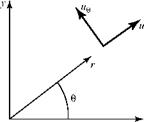
The polar-coordinate notation is reviewed in Fig. 4.14 to avoid confusion about signs. Note that the arrows on the velocity components indicate the positive direc­tion of the component and that the polar angle is measured from the positive x-axis, which here is the downstream direction.

1 Т/ a

—-*- = V cos 0

r 00 ”

-°^ = – V sin0

dr ”

Подпись: Ur = ue = Подпись: 1 - R2 *+R2 Подпись: (4.43)

The velocity components in polar coordinates are obtained by differentiating Eq. 4.41:

From this, it follows that on the surface of the cylinder (r = R), ur = 0. This is as it should be because there cannot be a flow component normal to a streamline. The fact that ur = 0 at the body surface r = R also indicates that the surface-boundary condition is satisfied. Also, from Eq. 4.43, u0 = -2V sin0 at r = R. Hence, there is a stagnation point on the body surface at 0 = n (i. e., the rear stagnation point on the

Uniform Flow Plus Source-Sink PairFigure 4.14. Polar-coordinate notation.

x-axis) and at 0 = 0 (i. e., the front stagnation point on the x-axis). Upstream of the body along the x-axis, 0 = n and u0 = -2V sin0 = 0 and ur < V because R < r. By substituting different values for r, Program PSI shows how ur begins to decrease about 10 cylinder radius upstream of the stagnation point and then decreases to zero at an increasing rate as r approaches the cylinder radius. The velocity component u0 at the top of the cylinder (0 = n/2) exhibits similar behavior with r for r > R. Thus, the disturbance due to even this blunt body dies out rather quickly in this low-speed flow. Finally, Eq. 4.43 shows that far from the body, r ^ ^ and V = VTC, which satisfies the boundary condition.

At 0 = n/2 on the surface of the cylinder, the tangential velocity has the (maximum) value u0 = -2VM (the minus sign indicates that the velocity is directed downstream). Finally, from the definition of the pressure coefficient for an incom­pressible, inviscid flow, on the surface of the cylinder:

Подпись: (4.44)Cp = 1 – – V4 = 1 – 4 sin2 0. V 2

Physically, a fluid particle approaching the cylinder along the x-axis decelerates to zero velocity at the upstream stagnation point. The particle next accelerates along the cylinder surface (recall that the flow is inviscid) until it reaches a velocity twice the freestream value at the top of the cylinder; it then decelerates along the rear half of the cylinder until it reaches a zero velocity at the rear stagnation point. The pressure coefficient has a value of +1.0 at the stagnation points and -3.0 at the top and bottom of the cylinder. Integration of the pressure (or pressure coefficient) dis­tribution on the surface of the cylinder yields zero lift and drag, a conclusion argued previously from symmetry.

example 4.11 Given: Consider the steady, incompressible, inviscid flow around a cylinder with zero lift.

Required: Predict the points on the upstream side of the cylinder where the sur­face static pressure is equal to the static pressure of the oncoming freestream.

Approach: The pressure-coefficient definition and the equation for the variation of pressure coefficient around the cylinder is used.

Solution: From Eqs. 4.27 and 4.44, with p set equal to pM at the point in question:

Cp = (p p~) = 0 = 1 -4sin20^0 =±30°, ±150°.

p iPV-2

Because the angle is the polar angle measured from the positive x-axis, the required points are at 0 = 150° and 0 = 210° on the upstream side of the cylinder.

Appraisal: The flow streamline along the x-axis stagnates on the cylinder at 0 = 180°. The flow on the surface of the cylinder (i. e., along that same stream­line) then accelerates and, from the Bernoulli Equation, as the velocity (i. e., dynamic pressure) increases, the static pressure must decrease. At a distance
along the surface of only 1/12 of the cylinder diameter, the pressure on the sur­face decreased from a maximum of freestream stagnation pressure to a value equal to the freestream static pressure. Continuing to the top of the cylinder, the velocity increases to a maximum and the static pressure on the cylinder reaches a minimum. The flow field around the cylinder is symmetric, with the freestream static pressure occurring on the surface of the cylinder at mirror-image points in both the x- and у-axes; only the locations on the upstream side of the cylinder were required.

Superposition of Elementary Solutions

Although a superposition can be carried out using either the elementary velocity potentials or stream functions, the superpositions discussed here are in terms of the stream function. The advantage of using the stream function is that the streamlines of the complicated flow then are generated automatically; recall that lines of у = constant are streamlines. In principle, for any flow generated by superposition, we can choose different constant values for the stream function; find pairs of values of (x, y) or (r,0), which make the superposed stream function equal to this constant; plot these coordinate pairs; and then find the streamlines by “joining the dots” (e. g., with a contour-plotting software package). In some cases, the streamline pattern may be found analytically from the superposition expression.

Uniform Flow Plus Source at Origin

This superposition uses the two solutions, Eqs. 4.29 and 4.32. Namely:

У = У UF + ¥s = V y+2Пtan 1 xy. (4.39)

For an illustrative flow problem, V and Л are constants that may be chosen arbi­trarily. The streamlines generated by joining the dots (as previously explained) can be examined by running the software Program PSI.

The following comments are pertinent to running Program PSI:

1. The flow is symmetrical about the x-axis. One streamline with a value у = —

passes through a stagnation point located on the x-axis. This may be seen by dif­ferentiating Eq. 4.39 to find u, v, and then setting these two velocity components equal to zero (because at a stagnation point, V = 0) and solving for (x, y). The result is:

Подпись: у = 0.Л

2nV ’

(The student should verify this result.) The value of this x, y pair, when substi­tuted into Eq. 4.39, yields the value of у on that stagnation streamline.

2. Recall that any streamline can be “cross-hatched” mentally to represent the sur­face of a solid body. The streamline passing through the stagnation point thus may be thought of as the surface of an open-ended (i. e., semi-infinite) body opening to the right. Vary the source strength, Л, and the freestream velocity values in the program to verify that the body shape changes as anticipated. Note that the location of the stagnation point along the x-axis changes as these parameters are varied. This is to be anticipated because the stagnation point occurs when the oncoming freestream flow is just balanced by the opposing source-flow streamline directed upstream along the x-axis.

3. Notice that the point source is located at the origin and, hence, inside the open-ended body. Thus, the fact that the velocity is infinite at the source is of no concern because the source is not within the external flow field around the body.

4. One of the other streamlines approaching the body in the second or third quad­rants may be “cross-hatched.” This streamline describes the flow along a plain and over a hill of continually increasing elevation.

5. Note that although the body shape (or hill) may be varied by varying the flow parameters, as in comment (2), the body shape comes out of the solution. Thus, we cannot easily specify a certain body shape in advance—“You get what you get.”