Category Dynamics of. Atmospheric Flight

INFLUENCE OF A FREE ELEVATOR ON LIFT AND MOMENT

In Sec. 6.3 we have dealt with the pitch stiffness of an airplane the controls of which are fixed in position. Even with a completely rigid structure, which never exists, a manually operated control cannot be regarded as fixed. A human pilot is incapable of supplying an ideal rigid constraint. When irreversible power controls are fitted, however, the stick-fixed condition is closely approximated. A characteristic of interest from the point of view of flying qualities is the stability of the airplane when the elevator is completely free to rotate about its hinge under the influence of the aerodynamic pressures that act upon it. Normally, the stability in the control-free condition is less than with fixed controls. It is desirable that this difference

INFLUENCE OF A FREE ELEVATOR ON LIFT AND MOMENT

Fig. 6.24 Elevator floating angle.


should be small. Since friction is always present in the control system, the free control is never realized in practice either. However, the two ideal conditions, free control and fixed control, represent the possible extremes. When the control is free, then Ghe = 0, so that from (6.5,2)

INFLUENCE OF A FREE ELEVATOR ON LIFT AND MOMENT

(6.6,1)


<5 =


The typical upward deflection of a free-elevator on a tail is shown in Fig. 6.24. The corresponding lift and moment are

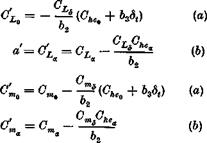
Подпись:Чее = °T^ + °L^e ^“free = ^mS^etree

After substituting( 6.6,1) into (6.6,2), we get

C4ree “ % + °L‘* (a)

INFLUENCE OF A FREE ELEVATOR ON LIFT AND MOMENT
Подпись: where
Подпись: (6.6,4)
Подпись: (6.5,6)

When, due consideration is given to the usual signs of the coefficients in these equations, we see that the two important gradients CLa and Cm are reduced in absolute magnitude when the control is released. This leads, broadly speaking, to a reduction of stability.

CONTROL HINGE MOMENT

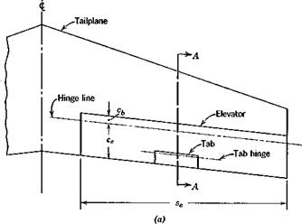
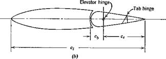
The aerodynamic forces on any control surface produce a moment about the hinge. Figure 6.21 shows a typical tail surface incorporating an elevator with a tab. The tab usually exerts a negligible effect on the lift of the aerodynamic surface to which it is attached, although its influence on the hinge moment is large.

The coefficient of elevator hinge moment is defined by

Here He is the moment, about the elevator hinge line, of the aerodynamic forces on the elevator and tab, 8e is the area of that portion of the elevator and tab that lies aft of the elevator hinge line, and ce is a mean chord of the same portion of the elevator and tab. Sometimes ce is taken to be the geo­metric mean value, i. e. ce = 8J2se, and other times it is the root-mean square of ce. The taper of elevators is usually slight, and the difference between the two values is generally small. The reader is cautioned to note which definition is employed when using reports on experimental measurements of Ghe.

Of all the aerodynamic parameters required in stability and control analysis, the hinge-moment coefficients are most difficult to determine with precision. A large number of geometrical parameters influence these co­efficients, and the range of design configurations is wide. Scale effects tend to be larger than for many other parameters, owing to the sensitivity of the hinge moment to the state of the boundary layer at the trailing edge. Two­dimensional airfoil theory shows that the hinge moment of simple flap controls

CONTROL HINGE MOMENT

CONTROL HINGE MOMENT

Fig. 6.21 Elevator and tab geometry, (a) Plan view, (b) Section A—A.

is linear with angle of attack and control angle in both subsonic and super­sonic flow.

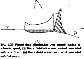
The normal-force distributions typical of subsonic flow associated with changes in a and <5 are shown qualitatively in Fig. 6.22. The force acting on the movable flap has a moment about the hinge that is quite sensitive to its location. Ordinarily the hinge moments in both cases (a) and (b) shown are negative.

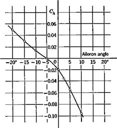
In many practical cases it is a satisfactory engineering approximation to assume that for finite surfaces Che is a linear function of a„ de, and 8t. The reader should note however that there are important exceptions in which strong nonlinearities are present. An example is the Frise aileron, shown with a typical Gh curve, in Fig. 6.23.

We assume that Ghe is linear, as follows,

Подпись: (6.5.1)

CONTROL HINGE MOMENT

@he — + Ъфе + M,

where by = = Che

b — ^he — c

– he*

b = c 3 ddt hes<

as is the angle of attack of the surface to which the control is attached (wing or tail), and <5, is the angle of deflection of the tab (positive down). The determination of the hinge moment then resolves itself into the determination of 60, blt b2, and b3. The geometrical variables that enter are elevator chord ratio cjct, balance ratio cblce, nose shape, hinge location, gap, trailing-edge angle, and planform. When a set-back hinge is used, some of the pressure acts ahead of the hinge, and the hinge moment is less than that of a simple flap with a hinge at its leading edge. The force that the control system must

CONTROL HINGE MOMENT

Fig. 6.23 Typical hinge moment of Frise aileron. Wing a = 2°. R. N. = 3.3 x 10®.


CONTROL HINGE MOMENT

exert to hold the elevator at the desired angle is in direct proportion to the hinge moment.

We shall find it convenient subsequently to have an equation like (6.5,1) with a instead of as. For tailless aircraft, as is equal to a, hut for aircraft with tails, as = ctt. Let us write for both types

@he Gh4 + 0ЛЄха. + Ъ2де + bsdt (6.5,2)

CONTROL HINGE MOMENT

where for tailless aircraft Che<) — b0, Che^ = bv For aircraft with tails, the relation between a and oct is derived from (6.3,25) and (6.3,32), i. e.

STATIC STABILITY LIMIT, hs

Подпись: h-K STATIC STABILITY LIMIT, hs Подпись: (6.4,25)

The critical C. G. position for zero elevator trim slope (i. e. for stability) can be found by setting (6.4,24) equal to zero. Recalling that Gmx = CL (h — hn), this yields

Подпись: orh — h,

where hs = hn ———— ——- (6.4,26)

0Lr + 2 CLe

STATIC STABILITY LIMIT, hs Подпись: (6.4,27)

Depending on the sign of Gmy, hs may be greater or less than hn. In terms of hs, (6.4,24) can be rewritten as

(h — hs) is the “stability margin,” which may be greater or less than the static margin.

FLIGHT DETERMINATION OF h„ AND hs

Подпись: or Подпись: dd c “^etrim vm® dCLuim Д ddetrim ..... GL. dGLtTim Д Подпись: (6.4.28) (6.4.29)

For the general case, (6.3,19) suggests that the measurement of hn requires the measurement of Gm and CL . Flight measurements of aerodynamic derivatives such as these can be made by dynamic techniques. However, in the simpler case when the complications presented by propulsive, com­pressibility, or aeroelastic effects are absent, then the relations implicit in Figs. 6.17 and 6.18 lead to a means of finding hn from the elevator trim curves. In that case all the coefficients of (6.4,13) are constants, and

Thus measurements of the slope of <5„ vs. GL^_m at various C. G. positions produce a curve like that of Fig. 6.20, in which the intercept on the h axis is the required N. P.

When speed effects are present, it is clear from (6.4,27) that a plot of (ddetrijJdV)t against h will determine hs as the point where the curve crosses the h axis.

VARIATION OF de WITH SPEED

‘’trim

When, in the absence of compressibihty, aeroelastie effects, and propulsive system effects, the aerodynamic coefficients of (6.4,13) are constant, the variation of &Нтіт with speed is simple. Then detrim is a unique function of CL for each C. G. position. Since CL is in turn fixed by the equivalent

trim trim

airspeed,! f°r horizontal flight

Подпись: (6.4,17)W

ipaV^S

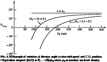
then <5etr. m becomes a unique function of vE. The form of the curves is shown in Fig. 6.18 for representative values of the coefficients.

The variation of <5„trlm with 0itrjm or speed shown on Figs. 6.17 and 6.18 is the normal and desirable one. For any O. G. position, an increase in trim speed from any initial value to a larger one requires a downward deflection of the elevator (a forward movement of the pilot’s control). The “gradient” of the movement /ЭГЛ is seen to decrease with rearward movement of

the C. G. until it vanishes altogether at the N. P. In this condition the pilot in effect has no control over trim speed, and control of the vehicle becomes very difficult. For even more rearward positions of the C. G. the gradient reverses, and the controllability deteriorates still further.

Подпись: FIG. 6.18 Example of variation of elevator angle to trim with speed and C.G. position. f Equivalent airspeed (EAS) is VE — vVp/pQ where pQ is standard sea-level density.

When the aerodynamic coefficients vary with speed, the above simple analysis must be extended. In order to be still more general, we shall in the

following explicitly include propulsive effects as well, by means of the parameter it, which stands for the state of the pilot’s propulsion control (e. g. throttle position), it — constant therefore denotes fixed-throttle and, of course, for horizontal flight at varying speed, tt must be a function of V that is compatible with T = D. For angles of climb or descent in the normal range of conventional airplanes L = W is a reasonable approximation, and we adopt it in the following. When nonhorizontal flight is thus included, tt becomes an independent variable, with the angle of climb у then becoming a function of tt, V, and altitude.

The two basic conditions then, for trimmed steady flight on a straight line are

Подпись:Подпись: (6.4,19)L = CLyV2S = W

and in accordance with the postulates made above, we write

Grn = У> Я-)

gl = CL{a, У, іг)

Now let ( )e denote one state that satisfies (6.4,18) and consider a small change from it, denoted by differentials, to another such state. From (6.4,18) we get, for p = const,

О

II

(6.4,20)

and

CLVS = const

or

2VeCLe dV + V*dCL = 0

so that

dOL = -2Gr — = -2GT dt

lje у L>e

(6.4,21)

where t is

defined in Table 5.1. Taking the differentials of (6.4,19) and

equating to (6.4,20 and 21) we get

Gia d* + CLd dde = – GL:r dn – (CLr + 2CL) dt 4

Cmx da + cme dde = —cmir dTT-Cmydt

Подпись: dde = I {[(C£F + 2 GLe)Gm- CLCmy dt + (CLCn VARIATION OF de WITH SPEED

where CLy = дСь/дУ and Gmy = dGmjdt. From (6.4,22) we get the solution for dd, as

There are two possibilities, tt constant and tt variable. In the first case

Подпись: О Подпись: V
VARIATION OF de WITH SPEED VARIATION OF de WITH SPEED
Подпись: (6.4,24)

It will be shown in Chapter 9 that the vanishing of this quantity is a true criterion of stability, i. e. it must be >0 for a stable airplane. In the second case, for example exactly horizontal flight, tt — tt(V) and the ir term on the r. h.s. of (6.4,23) remains. For such cases the gradient (ddetTimldV) is not necessarily related to stability. For purposes of calculating the propulsion contributions, the terms CL^ dir and Gmjr dir in (6.4,23) would be evaluated as dCL^ and dCm^ [see the notation of (6.3,13)]. These contributions to the lift and moment are discussed in Sec. 7.3.

Fm. 6.19 Reversal of <5trim slope at transonic speeds, тг = const.

The derivatives CLy and Gmy (see Sec. 7.8) may be quite large owing to slipstream effects on STOL airplanes, or Mach number effects near transonic speeds. These variations with M can result in reversal of the slope of <5etrlm as illustrated on Fig. 6.19. The negative slope at A, according to the stability criterion referred to above, indicates that the airplane is unstable at A. This can be seen as follows. Let the airplane be in equilibrium flight at the point A, and be subsequently perturbed so that its speed increases to that of В with no change in a or de. Now at В the elevator angle is too positive for trim: i. e. there is an unbalanced nose-down moment on the airplane. This puts the airplane into a dive and increases its speed still further. The speed will continue to increase until point G is reached, when the de is again the
correct value for trim, but here the slope is positive and there is no tendency for the speed to change any further.

. ELEVATOR ANGLE TO TRIM

<7 = СЛос) + C, (5,

-”trim / і etrim

= CL(*)-<^Cm(*)

^m6

(6.4,11)

When the linear lift and moment relations (6.4,2) apply the equations for trim are

@Lxatrim + CiA. — CL •* trim trim

^maatrim ^md^eiTim ‘

(6.4,12)

These equations are solved for a and de to give

__ ___ @mpL$ + ®трІ4хіш

^trim д

(a)

s ^’mpLx ~b ^mpLtvim

^etrim д

(6) (6.4,13)

^^etrim ^Lxi}l h ) ^trim A ^ A ^ Я)

(c)

where A = CLCmg – СъСтл

(d)

and is normally negative. The values of A for the two types of airplane are readily calculated from (6.4,8 and 9) together with (6.3,19) to give

Tailed:

A = GL[CLg(hn ~ hnwb) — ae V h

(a)

Tailless:

Д = Cr d°ma-c’ • a«5e

(6.4,14) (6) V ‘

and both are independent of h. From (6.4,13») we get the trimmed lift curve:

Gm 0Ts A

fi ______ то Ьg –

° i«t rim p ‘ p atrim (-‘ms

(6.4,16)

and the slope is given by

(d°L c Cl*c

Uajlrim Gmg m°

(6.4,16)

. ELEVATOR ANGLE TO TRIM

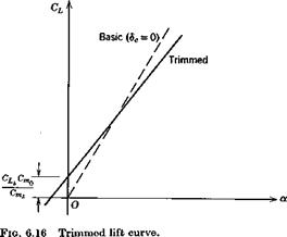
The trimmed lift-curve slope is seen to be less than CL by an amount that depends on (7 , i. e. on the static margin, and that vanishes when h hn.

The difference is only a few percent for tailed airplanes at normal C. G. position, but may be appreciable for tailless vehicles because of their larger CLa. The relation between the basic and trimmed lift curves is shown in Fig. 6.16.

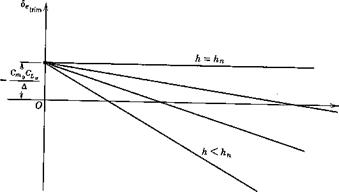
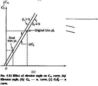
Equation (6.4,136) is plotted on Fig. 6.17, showing how <5etrim varies with CT and C. G. position when the aerodynamic coefficients are constant.

■^trira

. ELEVATOR ANGLE TO TRIM

Fig. 6.17 Elevator angle to trim at various C. G. positions.

LONGITUDINAL CONTROL

In this section we discuss the longitudinal control of the vehicle from a static point of view. That is, we concern ourselves with how the equilibrium state of steady rectilinear flight is governed by the available controls. Basically there are two kinds of changes that can be made by the pilot or
automatic control system—a change of propulsive thrust, or a change of configuration. Included in the latter are the operation of aerodynamic controls—elevators, wing flaps, spoilers, and horizontal tail rotation. Since the equilibrium state is dominated by the requirement Cm — 0, the most powerful controls are those that have the greatest effect on Cm.

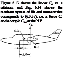
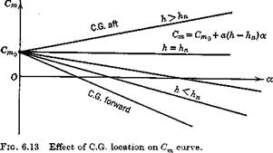
Figure 6.13 shows that another theoretically possible way of changing the trim condition is to move the C. G., which changes the value of a at which Cm = 0. Moving it forward reduces the trim a or CL, and hence produces an increase in the trim speed. This method was actually used by Lilienthal, a pioneer of aviation, in gliding flights during 1891—1896, in which he shifted his body to move the C. G. It has the inherent disadvantage, apart from practical difficulties, of changing Gmat the same time, reducing the pitch stiffness and hence stability, when the trim speed is reduced.

LONGITUDINAL CONTROL

The longitudinal control now generally used is aerodynamic. A variable pitching moment is provided by moving the elevator, which may be all or part of the tail, or a trailing-edge flap in a tailless design. Deflection of the elevator through an angle ёе produces increments in both the Gm and CL of the airplane. The ДCL caused by the elevator of aircraft with tails is small enough to be neglected for many purposes. This is not so for tailless aircraft, where the ACL due to elevators is usually significant. We shall assume that the lift and moment increments for both kinds of airplane are linear in de, which is a fair representation of the characteristics of typical controls at high Reynolds number. Therefore,

Подпись: (a) (6.4,2) ('b) Cl — Clxx + C, LSde Cm = + Стаде

LONGITUDINAL CONTROL

THE DERIVATIVES CLg AND Cm6

LONGITUDINAL CONTROL Подпись: дСь Подпись: де r Sf дОт dde 8 dde Подпись: (6.4,3)

Equation (6.3,14) gives the vehicle lift, with St = 0 for tailless types, of course. Hence

in which only the first term applies for tailless aircraft and the second for conventional tail elevators or all moving tails (when it is used instead of de).

We define the elevator lift effectiveness as

96’i(

ae = – ф

(6.4,4)

дбе

дСт St

От, = Lwb + ae *

6 дде 8

(6.4,5)

so that (6.4,3) becomes

LONGITUDINAL CONTROL

The total vehicle Cm is given for both tailed and tailless types by (6.3,15). For the latter, of course, VB = 0. Taking the derivative w. r.t. de gives

In the last case, the subscript wb is, of course, redundant and has been dropped. The primary parameters to be predicted or measured are ae for tailed aircraft, and dCLjdde, дСт /дде for tailless.

a«C’

LINEAR LIFT AND MOMENT

When the forces and moments on the wing, body, tail, and propulsive system are linear in a, as may be near enough the case in reality, some

Подпись: and LINEAR LIFT AND MOMENT

additional useful relations can be obtained. We then have

Furthermore, if Ст<л is linear in CL, it follows from (6.3,4) that Gm does not vary with CL, i. e. that a true aerodynamic center exists. Figure 6.10 shows that the tail angle of attack is

Подпись: (6.3.25) (6.3.26) Подпись: (6.3,27)at — awb + *’* — e

and hence

@Lt = aAamb + h ~ e)

The downwash є can usually be adequately approximated by

■ де

e = €0 — a,

9a

The downwash eg at CL = 0 results from the induced velocity field of the body and from wing twist; the latter produces a vortex wake and downwash field even at zero total lift. The constant derivative 9e/9a occurs because the main contribution to the downwash at the tail comes from the wing trailing vortex wake, the strength of which is, in the linear case, proportional to CL.

Подпись: Gr.. — ctf Подпись: •(-£H Подпись: (6.3,28)

The tail lift coefficient then is

and the total lift, from (6.3,14) is

CL =

– л jx *

wo^wb

i—– 1

i—‘

+ s5 а

і

9a/J

, St

+ at ~z (*<

О

“ €o)

(a)

or

Cl =

(CL)o + aV-wb

(b)

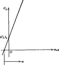
(6.3,29)

or

Cl =

act.

at ~ (h

(e)

where

II

e

o’

“ eo)

(6.3,30)

is the lift of the tail when a. wb = 0;

(■-!)] (взл1>

is the lift-curve slope of the whole configuration; and a is the angle of attack

Fig. 6.12 Graph of total lift.

LINEAR LIFT AND MOMENTof the zero-lift line of the whole configuration (see Fig. 6.12). Note that, since it is negative, then (CL)0 is negative. The difference between a and awb is found by equating (6.3,296 and c) to be

Подпись: (6.3,32)at,

* – «-wb = – ~ (h ~ eo)
a 8

When the linear relations for CL, CLi and Gm^

Note that since Cm is the pitching moment at zero a. wb, not at zero total lift, its value depends on h (via VH), whereas Cm, being the moment at zero total lift, represents a couple and is hence independent of C. G. position. All the above relations apply to tailless aircraft by putting VH = 0. Another useful relation comes from integrating (6.3,19), i. e.

Подпись: (a) (6.3,37) (b) Cm = + Gift1 ~ K)

or Cm = Ст0 + – h„)

Подпись:

LINEAR LIFT AND MOMENT

Fig. 6.14 Total lift and moment act­ing on vehicle.

TOTAL PITCHING MOMENT

On summing (6.3,4) and (6.3,12) and adding the contribution G^ for the propulsive system, we obtain the total pitching moment about the C. G.,

0» – ^a. e.rt + (cLwb + oLl I) (h – KJ – VHCLi + Cmv

(6.3,13)

Since CL is a coefficient based on 8t, then GL8tf8 is the tail contribution to CL, and the total lift coefficient of the vehicle is

Cl = C^ + (6.3,14)

Equation (6.3,13) therefore becomes

= ^a. e.ttS + – KJ – rHCLt + cmf (6.3,15)

It is worthwhile repeating that no assumptions about thrust, compressibility, or aeroelastic effects have been made in respect of (6.3,15). The pitch stiffness (—C ) is now obtained from (6.3,15). Recall that the aerodynamic centers of the wing-body combination and of the tail are fixed points, so that

C^ = + cLx(h – KJ – vHd-^ + ^ (6.3,16)

If a true aerodynamic center in the classical sense exists, then dO ^ Jda. is zero and

do, dcm

= Cu(h – KJ – Vh-£ + (6.3,17)

Cm^ as given by (6.3,16) or (6.3,17) is a constant that depends linearly on the C. G. position, h. Since CL^ is usually large, the magnitude and sign of Gm^ depend strongly on h. This is the, basis of the statement in Sec. 6.2 that C can always be made negative by a suitable choice of h. The C. G. position hn for which Gm is zero is of particular significance, since this represents a boundary between positive and negative pitch stiffness. In this book we define hn as the neutral point, N. P. It has the same significance for the vehicle as a whole as does the aerodynamic center for a wing alone, and indeed the term vehicle aerodynamic center is an acceptable alternative to “neutral point.”

TOTAL PITCHING MOMENT

The location of the N. P. is readily calculated from (6.3,16), i. e.

Подпись:(6.3,18)

(6.3,19) which is valid whether Gma c and Cm^ vary with a or not. Equation (6.3,19) clearly provides an excellent way of finding hn from test results, i. e. from measurements of Cm and CL. The difference between the C. G. position and the N. P. is sometimes called the static margin,

Подпись: (6.3,20)Kn = (K – h)

Since the criterion to be satisfied is C < 0, i. e. positive pitch stiffness, then we see that we must have h < hn, or Kn > 0. In other words the C. G. must be forward of the N. P. The farther forward the C. G. the greater is Kn, and in the sense of “static stability” the more stable the vehicle.

It must be emphasized that Gm and Gare partial derivatives. This means that all other significant arguments, normally M, CT, and p V2 are kept constant. This is especially important to keep in mind when experi­mental results are being used. If these parameters are unimportant or absent, as in the gliding flight of a rigid vehicle at low M, then Gm and 0L are functions of к only, Gm is a unique function of CL, and (6.3,19) yields

TOTAL PITCHING MOMENT(6.3,21)

Equation (6.3,21) is sometimes used in practice as a definition of the neutral point, but as is clear from the foregoing, it contains some dangers. Since Gm and CL are in the general case each functions of several independent variables, then the derivative dCmjdCL is not mathematically defined, and indeed different values for it can be calculated depending on what con­straints are imposed on the independent variables. With particular con­straints it indeed turns out to be a useful index of stability, and this point is treated further in Sec. 9.3.

PITCHING MOMENT OF A TAIL

The forces on an isolated tail are represented just like those on an isolated wing. When the tail is mounted on an airplane, however, important inter­ferences occur. The most significant of these, and one that is usually pre­dictable by aerodynamic theory, is a downward deflection of the flow at the tail caused by the wing. This is characterized by the mean downwash angle e. Blanking of part of the tail by the body is a second effect, and a reduction of the relative wind when the tail lies in the wing wake is the third.

PITCHING MOMENT OF A TAIL

Figure 6.10 depicts the forces acting on the tail. V is the relative wind vector of the airplane, and V’ is the average or effective relative wind at the tail. The tail lift and drag forces are by definition respectively perpendicular and parallel to V’. The reader should note the tail angle it, which in keeping with Fig. 6.5 must be negative. The moment Ma c is the pitching moment of the tail about its own aerodynamic center. This is zero for a symmetrical tail section, and in any case would come mainly from the deflection of the elevator.

The contribution of the tail to the airplane lift, which by definition is perpendicular to V, is

Lt cos e — Dt sin e

PITCHING MOMENT OF A TAIL

e is usually a small angle, and Dte may be neglected compared with Lt. The contribution of the tail to the airplane lift then becomes simply Lt. We introduce the symbol CL to represent the lift coefficient of the tail, based on the airplane dynamic pressure JtpV2 and the tail area St.

The reader should note that the lift coefficient of the tail is often based on the local dynamic pressure at the tail, which differs from JpF2 when the tail lies in the wing wake. This practice entails carrying the ratio V’JV in many subsequent equations. The definition employed here amounts to incorporating V’JV into the tail lift-curve slope at = dCLJdctt. This quantity is in any event different from that for the isolated tail, owing to the interference effects previously noted. This circumstance is handled in various ways in the literature. Sometimes a tail efficiency factor rjt is introduced, the isolated tail lift slope being multiplied by rj(. In other treatments, t]t is used to represent (V’JV)2. In the convention adopted here, at is the lift-curve slope of the tail, as measured in situ on the airplane, and based on the dynamic pressure pV2. This is the quantity that is directly obtained in a wind-tunnel test.

From Fig. 6.10 we find the pitching moment of the tail about the C. G. to be

= —lt[Lt cos (xwb — e) + Dt sin (xwb — є)]

– *([•£>( cos (xwb — e) — Lt sin (xwb – €)] + MaC( (6.3,6)

Experience has shown that in the majority of instances the dominant term in this equation is the first one, and that all others are negligible by com­parison. Only this case will be dealt with here. The reader is left to extend the analysis to situations where this approximation is not valid. With the above approximation, and that of small angles,

PITCHING MOMENT OF A TAIL Подпись: (6.3,7)

Mt = – ltLt = – ltCLilPV2St Upon conversion to coefficient form, we obtain

The combination ltStJ8c, is the ratio of two volumes characteristic of the airplane’s geometry. It is commonly called the “horizontal-tail volume ratio,” or more simply, the “tail volume.” It is denoted here by VH. Thus

COT( — — V H®Lt (6.3,8)

Since the center of gravity is not a fixed point, but varies with the loading condition and fuel consumption of the vehicle, VH in (6.3,8) is not a constant

PITCHING MOMENT OF A TAIL

Fig. 6.11 Wing-body and tail aerodynamic centers.

(although it does not vary much). It is a little more convenient to calculate the moment of the tail about a fixed point, the mean aerodynamic center of the wing-body combination, and to use this moment in the subsequent algebraic manipulations. Figure 6.11 shows the relevant relationships, and we define

VH = ^ (6-3,9)

cS

which leads to

rH = Vs-^(h-hnJ (6.3,10)

The moment of the tail about the wing-body aerodynamic center is then [cf. (6.3,8)]

Cmt=-VHCLi (6.3,11)

and its moment about the C. G, is, from substitution of (6.3,10) into (6.3,8)

= – УвОц + CLt I (h ~ KJ (6-3,12)

PITCHING MOMENT OF A PROPULSIVE SYSTEM

The moment provided by a propulsive system is in two parts: (1) that coming from the forces acting on the unit itself, e. g. the thrust and in-plane force acting on a propeller, and (2) that coming from the interaction of the propulsive slipstream with the other parts of the airplane. These are dis­cussed in more detail in Sec. 7.3. We assume that the interference part is included in the moments already given for the wing, body, and tail, and denote by the remaining moment from the propulsion units.

PITCHING MOMENT OF A BODY AND NACELLES

The influence of the body and nacelles are complex. A body alone in an airstream is subjected to aerodynamic forces. These, like those on the wing, may be represented over moderate ranges of angle of attack by lift and drag forces at an aerodynamic center, and a pitching couple. When the wing and body are put together, however, a simple superposition of the aerodynamic forces which act upon them separately does not give a correct result. Strong interference effects are usually present, the flow field of the wing affecting the forces on the body, and vice versa.

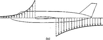
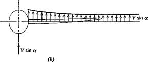
These interference flow fields are illustrated for subsonic flow in Fig. 6.9. Part (a) shows the pattern of induced velocity along the body that is caused by the wing vortex system. This induced flow produces a positive moment that increases with wing lift or a. Hence a positive (destabilizing) contribution to Gm results. Part (6) shows an effect of the body on the wing. When the body axis is at angle a to the stream, there is a cross-flow com­ponent V sin a. The body distorts this flow locally, leading to cross-flow

PITCHING MOMENT OF A BODY AND NACELLES

PITCHING MOMENT OF A BODY AND NACELLES

Fig. 6.9 Example of mutual interference flow fields of wing and body—subsonic flow. (a) Qualitative pattern of upwash and downwash induced along the body axis by the wing vorticity. (6) Qualitative pattern of upwash induced along wing by the cross-flow past the body.

components that can be of order 2 V sin a at the body-wing intersection. There is a resulting change in the wing lift distribution.

The result of adding a body and nacelles to a wing may usually be inter­preted as a shift (forward) of the mean aerodynamic center, an increase in the lift-curve slope, and a negative increment in Cma . The equation that corresponds to (6.3,3) for a wing-body-nacelle combination is then of the same form, but with different values of the parameters. The subscript wb is used to denote these values.

G^ = omM, wb + cLJh-KJ (6.3Д)