Category Dynamics of Flight

The p Derivatives (Cyp, Clp, C„p)

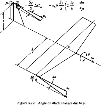
When an airplane rolls with angular velocity p about its x axis (the flight direction), its motion is instantaneously like that of a screw. This motion affects the airflow (lo­cal angle of attack) at all stations of the wing and tail surfaces. This is illustrated in Fig. 5.12 for two points: a wing tip and the fin tip. It should be noted that the nondi­mensional rate of roll, p = pb/2u0 is, for small p, the angle (in radians) of the helix traced by the wing tip. These angle of attack changes bring about alterations in the aerodynamic load distribution over the surfaces, and thereby introduce perturbations in the forces and moments. The change in the wing load distribution also causes a modification to the trailing vortex sheet. The vorticity distribution in it is no longer symmetrical about the x axis, and a sidewash (positive, i. e., to the right) is induced at a vertical tail conventionally placed. This further modifies the angle-of-attack distri­bution on the vertical-tail surface. This sidewash due to rolling is characterized by the derivative da/dp. It has been studied theoretically and experimentally by Michael (1952), who has shown its importance in relation to correct estimation of the tail con­tributions to the rolling derivatives. Finally, the helical motion of the wing produces a trailing vortex sheet that is not flat, but helical. For the small rates of roll admissible in a linear theory, this effect may be neglected with respect to both wing and tail forces.

THE DERIVATIVE Cv

Ур

The side force due to rolling is often negligible. When it is not, the contributions that need to be considered are those from the wing[15] and from the vertical tail. The verti­cal-tail effect may be estimated in the light of its angle-of-attack change (see Fig. 5.12) as follows. Let the mean change in aF (see Fig. 3.12) due to the rolling velocity be

* Pzf, dcr

AaF =——– + p

u0 dp

where zF is an appropriate mean height of the fin. Introducing the nondimensional rate of roll, we may rewrite this as

Подпись: (5.7,1)Подпись: (5.7,2)/ zF da

д„,= -р(2–¥

The incremental side-force coefficient on the fin is obtained from Aah

Zf da

ДCVF = aF AaF = ~aFp ( 2 — —

The p Derivatives (Cyp, Clp, C„p)

where aF is the lift-curve slope of the vertical tail. The incremental side force on the airplane is then given by

Подпись: (5.7,3)
The p Derivatives (Cyp, Clp, C„p) The p Derivatives (Cyp, Clp, C„p) The p Derivatives (Cyp, Clp, C„p)

thus

THE DERIVATIVE C,

lP

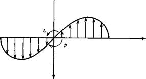
Clp is known as the damping-in-roll derivative. It expresses the resistance of the air­plane to rolling. Except in unusual circumstances, only the wing contributes signifi­cantly to this derivative. As can be seen from Fig. 5.12, the angle of attack due to p varies linearly across the span, from the value pb/2u0 at the right wing tip to —pb/2u0 at the left tip. This antisymmetric a distribution produces an anti-symmetric incre­ment in the lift distribution as shown in Fig. 5.13. In the linear range this is superim­posed on the symmetric lift distribution associated with the wing angle of attack in undisturbed flight. The large rolling moment L produced by this lift distribution is proportional to the tip angle of attack p (see Fig. 5.12), and Clp is a negative constant, so long as the local angle of attack remains below the local stalling angle.

If the wing angle of attack at the center line, aw(0), is large, then the incremental value due to p may take some sections of the wing beyond the stalling angle, as

The p Derivatives (Cyp, Clp, C„p)

Figure 5.13 Spanwise lift distribution due to rolling.

shown in Fig. 5.14. [Actually, for finite span wings, there is an additional induced an­gle of attack distribution a,(y) due to the vortex wake that modifies the net sectional value still further. We neglect this correction here in the interest of making the main point.] When this happens Clpp is reduced in magnitude from the linear value and if aw(0) is large enough, will even change sign. When this happens, the wing will au­torotate, the main characteristic of spinning flight.

CONTRIBUTIONS OF A TAIL

Подпись: Ae = — -r— a At = da
CONTRIBUTIONS OF A TAIL

There is an approximate method for evaluating the contributions of a tail surface, which is satisfactory in many cases. This is based on the concept of the lag of the downwash. It neglects entirely the nonstationary character of the lift response of the tail to changes in tail angle of attack, and attributes the result entirely to the fact that the downwash at the tail does not respond instantaneously to changes in wing angle of attack. The downwash is assumed to be dependent primarily on the strength of the wing’s trailing vortices in the neighborhood of the tail. Since the vorticity is con­verted with the stream, then a change in the circulation at the wing will not be felt as a change in downwash at the tail until a time At — l,/u0 has elapsed, where l, is the tail length. It is therefore assumed that the instantaneous downwash at the tail, e(r), corresponds to the wing a at time (t — At). The corrections to the quasistatic down – wash and tail angle of attack are therefore

(5.5,9)

Cz of a Tail

Za

CONTRIBUTIONS OF A TAIL Подпись: (5.5,10)

The correction to the tail lift coefficient for the downwash lag is

The correction to the airplane lift is therefore

Подпись:AC, = a. a

Therefore

dCz dCL де l, S,

CONTRIBUTIONS OF A TAIL

and

Cm. of a Tail

ma

The correction to the pitching moment is obtained from ACLt as

Эе l,

ACm = ~VH ACL = —a-jCt — VH

da u0

Подпись: and CONTRIBUTIONS OF A TAIL Подпись: l, de c da Подпись: (5.5,12)

Therefore

5.2 The P Derivatives (Cyp, Clp, Cnp)

These derivatives all are obtainable from wind-tunnel tests on yawed models (Camp­bell and McKinney, 1952). Generally speaking, estimation methods do not give com­pletely reliable results, and testing is a necessity.

THE DERIVATIVE Cyp

CONTRIBUTIONS OF A TAIL

This is the side-force derivative, giving the force that acts in the у direction (right) when the airplane has a positive /3 or v (i. e., a sideslip to the right, see Fig. 3.11). Cyp is usually negative, and frequently small enough to be neglected entirely. The main contributions are those of the body and the vertical tail, although the wing, and wing – body interference, may modify it significantly. Of these, only the tail effect is readily estimated. It may be expressed in terms of the vertical-tail lift-curve slope and the sidewash factor (see Sec. 3.9). (In this and the following sections the fin velocity ra­tio VFIV is assumed to be unity.)

or

CONTRIBUTIONS OF A TAIL(5.6,1)

The most troublesome component of this equation is the sidewash derivative dcr/d/3, which is difficult to estimate because of its dependence on the wing and fuselage geometry (see Sec. 3.9).

THE DERIVATIVE Clp

C, p is the dihedral effect, which was discussed at some length in Sec. 3.12.

THE DERIVATIVE Cnp

C,4, is the weathercock stability derivative, dealt with in Sec. 3.9.

The a Derivatives (CL&, CmJ

The a derivatives owe their existence to the fact that the pressure distribution on a wing or tail does not adjust itself instantaneously to its equilibrium value when the angle of attack is suddenly changed. The calculation of this effect, or its measure­ment, involves unsteady flow. In this respect, the a derivatives are very different from those discussed previously, which can all be determined on the basis of steady-state aerodynamics.

CONTRIBUTIONS OF A WING

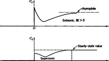
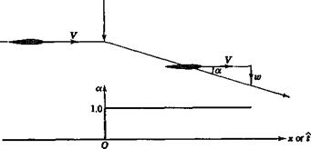
Consider a wing in horizontal flight at zero a. Let it be subjected to a downward im­pulse, so that it suddenly acquires a constant downward velocity component. Then, as shown in Fig. 5.7, its angle of attack undergoes a step increase. The lift then responds in a transient manner (the indicial response) the form of which depends on whether M is greater or less than 1. In subsonic flight, the vortices which the wing leaves be­hind it can influence it at all future times, so that the steady state is approached only asymptotically. In supersonic flight, the upstream traveling disturbances move more slowly than the wing, so that it outstrips the disturbance field of the initial impulse in a finite time tx. From that time on the lift remains constant.

In order to find the lift associated with a, let us consider the motion of an airfoil with a small constant a, but with q = 0. The motion, and the angle of attack, are
The a Derivatives (CL&, CmJ

The a Derivatives (CL&, CmJ

О t.

Figure 5.7 Lift response to step change in a. (After Tobak, NACA Rept. 1188.)


The a Derivatives (CL&, CmJ

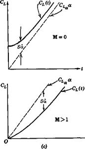
shown in Fig. 5.8. The method used follows that introduced by Tobak (1954). We as­sume that the differential equation which relates CL{t) with a(i) is linear. Hence the method of superposition (the convolution integral) may be used to derive the re­sponse to a linear a{t). Let the response to a unit step be A(i). Then the lift coefficient at time і is (see Appendix A.3).

CL{i) = [ A(i – т)а(т) dT

JT=0

The a Derivatives (CL&, CmJ

Since d(r) = constant, then

The a Derivatives (CL&, CmJ

The a Derivatives (CL&, CmJ

Figure 5.8 Lift associated with a.

The ultimate CL response to a unit-step a input is CLa. Let the lift defect be /(f): that is,

мі) = cLa – m

Then (5.5,1) becomes

CL(i) = aCLt – a [ f(t ~ t) dr

jt=0

= CLaa — Sa (5.5,2)

where 5(f) = //=0 /(? – t) dr. The term S d is shown on Fig. 5.8. Now, if the idea of representing the lift by means of aerodynamic derivatives is to be valid, we must be able to write, for the motion in question,

lm


j«“o


The a Derivatives (CL&, CmJ

Figure 5.9 Vector diagram of lift response to oscillatory a.


where CLa and CLix are constants. Comparing (5.5,2) and (5.5,3), we find that C, a = – S(t), a function of time. Hence, during the initial part of the motion, the derivative concept is invalid. However, for all finite wings,[11] the area 5(f) converges to a finite value as і increases indefinitely. In fact, for supersonic wings, S reaches its limiting value in a finite time, as is evident from Fig. 5.7. Thus (5.5,3) is valid,[12] with constant CLa, for values of t greater than a certain minimum. This minimum is not large, being the time required for the wing to travel a few chord lengths. In the time range where S is constant, or differs only infinitesimally from its asymptotic value, the CL(t) curve of Fig. 5.8c is parallel to CLa a. A similar situation exists with respect to Cm.

We see from Fig. 5.8 that Cu, which is the lim — 5(f), can be positive for M = 0 and negative for larger values of M.

There is a second useful approach to the a derivatives, and that is via considera­tion of oscillating wings. This method has been widely used experimentally, and ex­tensive treatments of wings in oscillatory motion are available in the literature,[13] pri­marily in relation to flutter problems. Because of the time lag previously noted, the amplitude and phase of the oscillatory lift will be different from the quasisteady val­ues. Let us represent the periodic angle of attack and lift coefficient by the complex numbers

a = a0e‘a>l and C, = CUle‘°“ (5.5,4)

where a0 is the amplitude (real) of a, and CU) is a complex number such that |Qj is the amplitude of the CL response, and arg Си is its phase angle. The relation between Си and a0 appropriate to the low frequencies characteristic of dynamic stability is il­lustrated in Fig. 5.9. In terms of these vectors, we may derive the value of CLu as fol­lows. The a vector is

a = io)a0e, a“

Thus CL may be expressed as

CL = R[C, Je^ + iI[CLo]eia“

Подпись: a wa0 = R[C, J — + /[CJ

«о

The a Derivatives (CL&, CmJ
Подпись: Hence
Подпись: (5.5,5)

or, if the amplitude a0 is unity, C,. = /[C^J/k, where к is the reduced frequency coc/2u0.

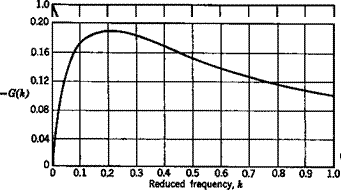
Подпись: where The a Derivatives (CL&, CmJ Подпись: G(kY Подпись: (5.5,6)

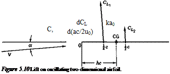
To assist in forming a physical picture of the behavior of a wing under these con­ditions, we give here the results for a two-dimensional,[14] airfoil in incompressible flow. The motion of the airfoil is a plunging oscillation; that is, it is like that shown in Fig. 5.2a, except that the flight path is a sine wave. The instantaneous lift on the air­foil is given in two parts (see Fig. 5.10):

and F(k) and G(k) are the real and imaginary parts of the Theodorsen function C(k) plotted in Fig. 5.11 (Theodorsen, 1934). The lift that acts at the midchord is propor­tional to a = z/u0, where г is the translation (vertically downward) of the airfoil. That is, it represents a force opposing the downward acceleration of the airfoil. This force is exactly that which is required to impart an acceleration г to a mass of air contained in a cylinder, the diameter of which equals the chord c. This is known as the “appar­ent additional mass.” It is as though the mass of the airfoil were increased by this amount. Except in cases of very low relative density ц = 2m/pSc, this added mass is small compared to that of the airplane itself, and hence the force CLl is relatively unimportant. Physically, the origin of this force is in the reaction of the air which is associated with its downward acceleration. The other component, CLl, which acts at the chord point, is associated with the circulation around the airfoil, and is a conse­quence of the imposition of the Kutta-Joukowski condition at the trailing edge. It is seen that it contains one term proportional to a and another proportional to a. From Fig. 5.10, the pitching-moment coefficient about the CG is obtained as

cm = CLl(h – I) + CL2(h – I) (5.5,7)

The a Derivatives (CL&, CmJ

From [(5.5,6) and (5.5,7)], the following derivatives are found for frequency k.

Подпись: C, The a Derivatives (CL&, CmJ

CLa = 2irF(k)

Cma = 2irF(k)(h – h) (5.5,8)

, G(k)

cmh = 77{h~D + 2tt—— (h – )

The awkward situation is evident, from (5.5.8), that the derivatives are frequency-de­pendent. That is, in free oscillations one does not know the value of the derivative un­til the solution to the motion (i. e. the frequency) is known. In cases of forced oscilla­tions at a given frequency, this difficulty is not present.

When dealing with the rigid-body motions of flight vehicles, the characteristic nondimensional frequencies к are usually small, к < 1. Hence it is reasonable to use the F(k) and G(k) corresponding to к —» 0. For the two-dimensional incompressible case described above, lim F{k) = 1, so that CLa = 2тг and Cma = 2Mh – J), the theo­retical steady-flow values. This conclusion, that CLa and Cma are the quasistatic values, also holds for finite wings at all Mach numbers. The results for CLt and Cm& are not so clear, however, since lim G(k)/k given above is infinite. This singularity is marked for the example of two-dimensional flow given above, but is not evident for finite wings at moderate aspect ratio. Miles (1950) indicates that the к log к term responsi-

ble for the singularity is not significant for aspect ratios less than 10, and the numeri­cal calculations of Rodden and Giesing (1970) show no difficulty at values of к as low as 0.001. Filotas’ (1971) solutions for finite wings bear out Miles’ contention. Thus for finite wings definite values of CLit and Cm. t can be associated with small but nonvanishing values of k. The limiting values described above can be obtained from a first-order-in-frequency analysis of an oscillating wing. To summarize, the a deriva­tives of a wing alone may be computed from the indicial response of lift and pitching moment, or from first-order-in-frequency analysis of harmonically plunging wings.

PITCH DAMPING OF PROPULSIVE JETS

When gases flow at high speed inside jet or rocket engines at the same time as the ve­hicle is rotating in pitch or yaw, they react against the walls of the ducts with a force perpendicular to their velocity vector (the Coriolis force). This reaction can result in a pitching moment proportional to q, that is, in a contribution to Cmq, (and similarly to Cn). An analysis of this effect is given in Sec. 7.9 of Etkin (1972).

For jet airplanes in cruising flight this contribution to Cmq is usually negligible. Only at high values of CT, and when the Cmq of the rest of the airplane is small, would it be significant. On the other hand, a rocket booster at lift-off, when the speed is low, has practically zero external aerodynamic damping and the jet damping be­comes very important.

DEPENDENCE ON h

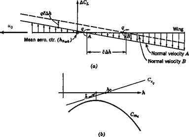
Because the axis of rotation in Fig. 5.5, passes through the CG, the results obtained are dependent on h. The nature of this variation is found as follows. Let the axis of rotation be at A in Fig. 5.6, and let the associated lift and moment be

CLa = CLqAq CmA — C^q (5.4,7)

Now let the axis of rotation be moved to B, with the change in normal velocity distri­bution shown on the figure. Since the two normal velocity distributions differ by a constant, (the upward translation qc Ah) the difference between the two pressure dis­tributions is that associated with a flat plate at angle of attack

a = — —— Ah (5.4,8)

u0

This angle of attack introduces a lift increment acting at the wing mean aerodynamic center of amount

ACL = CLa= AhCL = -2CL q Ah

“ «о “

DEPENDENCE ON h

Figure 5.6 Effect of CG location on CZq, Cm.

We see that CLq is linear in h, and can therefore be expressed as

CLq = ~2CLa(h – ho) (5.4,11)

where h0 is the CG location at which CZq is zero. By virtue of (5.1,1) we get

CZq = ~CLq = 2CLa(h – h0) (5.4,12)

The pitching moment about the CG is

Cm = Cmac + CL(h – hnJ (5.4,13)

so that Cmq=-^ + CLq(h-h„J

= – 2CLa(h – h0)(h – hj (5.4,14)

Equation (5.4,14) shows that Cmq is quadratic in h. We can write it without loss of generality as

Cmq = Cmq – 2ClJJi – h)2 (5.4,15)

where Cmq is the maximum (least negative) value of Cmq and h is the CG location where it occurs (see Fig. 5.6b). The value of h is found by differentiating (5.4,14). This yields

The linear theory of two-dimensional thin wings gives for supersonic flow:

Подпись: =
Подпись: 3VM2 - 1 Подпись: (5.4,17)

h0 = h =

and for subsonic flow:

h0 4

h = I (5.4,18)

CONTRIBUTIONS OF A WING

As previously remarked, on airplanes with tails the wing contributions to the q deriv­atives are frequently negligible. However, if the wing is highly swept or of low aspect ratio, it may have significant values of C and Cmq and of course, on tailless air­planes, the wing supplies the major contribution. The q derivatives of wings alone are therefore of great engineering importance.

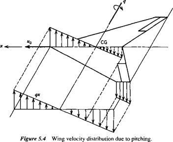
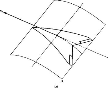
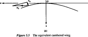
Unfortunately, no simple formulas can be given, because of the complicated de­pendence on the wing planform and the Mach number. However, the following dis­cussion of the physical aspects of the flow indicates how linearized wing theory can be applied to the problem. Consider a plane lifting surface, at zero ax, with forward speed u0 and angular velocity q about a spanwise axis (see Fig. 5.4). Each point in the wing has a velocity component, relative to the resting atmosphere, of qx normal to the surface. This velocity distribution is shown in the figure for the central and tip chords. Now there is an equivalent cambered wing that would have the identical dis­tribution of velocities normal to its surface when in rectilinear translation at speed n0. This is illustrated in Fig. 5.5a. The cross section of the curved surface S is shown in (b). The normal velocity distribution will be the same as in Fig. 5.4 if

Подпись: dz _ q Эх u0CONTRIBUTIONS OF A WINGx

CONTRIBUTIONS OF A WING

Hence

CONTRIBUTIONS OF A WING

and the cross section of S is a parabolic arc. In linearized wing theory, both subsonic and supersonic, the boundary condition is the same for the original plane wing with rotation q and the equivalent curved wing in rectilinear flight. The problem of finding the q derivatives then is reduced to that of finding the pressure distribution over the equivalent cambered wing. Because of the form of (5.4,5), the pressures are propor­tional to qlu0. From the pressure distribution, CZq and Cmq can be calculated. The de­rivatives can in principle also be found by experiment, by testing a model of the equivalent wing.

The values obtained by this approach are quasistatic; i. e., they are steady-state values corresponding to ax = 0 and a small constant value of q. This implies that the flight path is a circle (as in Fig. 3.1), and hence that the vortex wake is not rectilinear. Now both the linearized theory and the wind-tunnel measurement apply to a straight wake, and to this extent are approximate. Since the values of the derivatives obtained are in the end applied to arbitrary flight paths, as in Fig. 5.2b, there is little point in correcting them for the curvature of the wake.

The error involved in the application of the quasistatic derivatives to unsteady flight is not as great as might be expected. It has been shown that, when the flight path is a sine wave, the quasistatic derivatives apply so long as the reduced frequency is small, that is,

k = — < (5.4,6)

2 u0

where to is the circular frequency of the pitching oscillation. If / is the wavelength of the flight path, then

c

к = тг —

so that the condition к 1 implies that the wavelength must be long compared to the chord, for example, l > 60c for к < 0.05.

CONTRIBUTIONS OF A WING

CONTRIBUTIONS OF A WING

CONTRIBUTIONS OF A TAIL

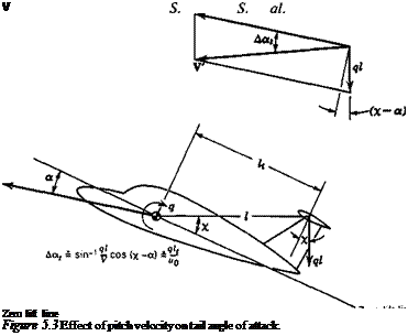
As illustrated in Fig. 5.3, the main effect of q on the tail is to increase its angle of at­tack by (ql,/u0) radians, where u0 is the flight speed. It is this change in a, that ac­counts for the changed forces on the tail. The assumption is implicit in the following derivations that the instantaneous forces on the tail correspond to its instantaneous angle of attack; i. e., no account is taken of the fact that it takes a finite time for the tail lift to build up to its steady-state value following a sudden change in q. (A method of including this refinement has been given by Tobak, 1954.) The derivatives obtained are therefore quasistatic.

Cz of the Tail

Zq

By definition, CZq = (dCzldq)0 = (2u0lc){bCzldq)0, and, from (5.1,1), (dCz/dq)0 = — (ЭCL/dq)0. The change in tail lift coefficient caused by the rotation q is

Подпись: (5.4,1)ql,

AQ, = aJSa, = a, —

u0

CONTRIBUTIONS OF A TAIL

and the corresponding change in airplane lift coefficient is

Therefore


CONTRIBUTIONS OF A TAIL

and


CONTRIBUTIONS OF A TAIL(5.4,2)

Cmq of the Tail

CONTRIBUTIONS OF A TAIL

The increment in pitching moment that corresponds to AC/ ( is [see (2.2,9)]

Подпись: and CONTRIBUTIONS OF A TAIL Подпись: c Подпись: (5.4,3)

Hence

The q Derivatives (CZq, CmJ

The q Derivatives (CZq, CmJ

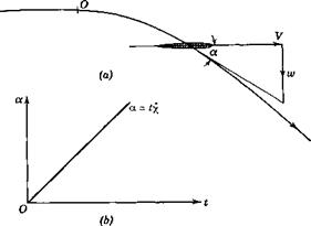
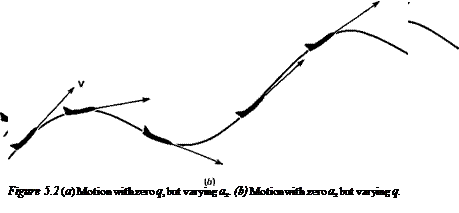
These derivatives represent the aerodynamic effects that accompany rotation of the airplane about a spanwise axis through the CG while ax remains zero. An example of this kind of motion was treated in Sec. 3.1 (i. e., the steady pull-up). Figure 5.2b shows the general case in which the flight path is arbitrary. This should be contrasted with the situation illustrated in Fig. 5.2a, where q = 0 while ax is changing.

Both the wing and the tail are affected by the rotation, although, when the air­plane has a tail, the wing contribution to CZq and Cmq is often negligible in compari­son with that of the tail. In such cases it is common practice to increase the tail effect by an arbitrary amount, of the order of 10%, to allow for the wing and body.

The и Derivatives (CXu, CZu, CmJ

The и Derivatives (CXu, CZu, CmJ Подпись: = 1 + 2An

The и derivatives give the effect on the forces and moments of an increase in the for­ward speed, while the angle of attack, the elevator angle, and the throttle position re­main fixed. If the coefficients of lift and drag did not change, then this would imply an increase in these forces in accordance with the speed-squared law, i. e.,

Since the pitching moment is initially zero, then, so long as Cm does not change with u, it will remain zero. The situation is actually more complicated than this, for the nondimensional coefficients are in general functions of Mach number and Reynolds number, both of which increase with increasing u. The variation with Reynolds num­ber is usually neglected, but the effect of Mach number must be included.

The thrust effect shows up in two different ways. One stems simply from the de­rivative of thrust with speed, which depends on the type of propulsive system-jet, propeller, and so forth. The other, related mainly to propeller configurations, derives from the propulsion/airframe interaction, for example, the propeller slipstream im­pinging on the wing. This is an important effect, and for some STOL airplanes, may be dominant at low speeds.

Finally, the increased loading on the airframe due to the speed increase may in­duce significant structural distortion. This is a static aeroelastic effect. For example, the tail lift coefficient may be influenced appreciably by the loading (see Sec. 3.5). An appropriate variable to use for aeroelastic effects is the dynamic pressure pd =

In order to formally include each of these three major effects, compressibility, aeroelasticity, and propulsive, even though they would rarely all be present at the same time, each of the coefficients Cx, Cz, Cm is assumed to be a function of M, pd, and CT as well as angle of attack.

We then have

The и Derivatives (CXu, CZu, CmJ(5.3,1)

and similarly for CZu and Cmu.

CALCULATION OF дМІдй

Подпись: C,„ M0 Подпись: Э CT Ж The и Derivatives (CXu, CZu, CmJ Подпись: dCo dpd Подпись: I +cTu 0 The и Derivatives (CXu, CZu, CmJ Подпись: (5.3,11)

Since the direct aeroelastic effect on thrust is likely to be negligible, we neglect dCT/dpd, and then (5.3,5) gives

When a powered wind-tunnel model is tested, it is common practice to measure the net axial force coefficient Cx and not its component parts C, and CD. In that case, the test data can provide the CXu derivative directly.

THE DERIVATIVE CZu

Подпись: T/0Подпись: T/0

Подпись: so that Подпись: Q„ = Подпись: -Mn Подпись: де, ЭМ Подпись: pul The и Derivatives (CXu, CZu, CmJ Подпись: (5.3,12)
Подпись: ЭС-

From (5.1,1) we have that

Подпись: CL Подпись: ata V1 — M2 cos2 A Подпись: M cos Л < 1

The derivative М0(ЭС,/ЭМ0) tends to be small except at transonic speeds. Theoretical values are easily calculated for high-aspect-ratio swept wings. At subsonic speeds, the Prandtl-Glauert rule combined with simple sweep theory (Kuethe and Chow, 1976) gives the lift coefficient for two-dimensional flow as

where a, is the lift-curve slope in incompressible flow and A is the sweepback angle of the і chord line. Upon differentiation with respect to M, we get

dCL M2 cos2 A

M “ ~ =———- 5— 7— C,

Подпись: and hence

ЭМ 1 — M2 cos2 Л

Подпись: (5.3,13)/ dCL Mo cos2 Л

0 ЭМ j0 1 — Mo cos2 Л ^’Lo

In level flight with the lift equal to the weight, MlCLo is constant, and hence М0(ЭС^/ЭМ)0 is proportional to 1/(1 — M2, cos2 Л). At supersonic speeds, the two-di­mensional lift is given by Kuethe and Chow (1976)

4a cos Л
VM2 cos2 A – 1

After differentiation with respect to M, we get exactly the same result as for subsonic speeds. That is (5.3,13) applies over the whole Mach-number range, except of course near M = 1 where the cited airfoil theories do not apply. Low-aspect-ratio wings are less sensitive to changes in M.

THE DERIVATIVE Г

mu

Подпись: C, Подпись: = M Подпись: dCm ЭМ Подпись: I + pul 0 The и Derivatives (CXu, CZu, CmJ Подпись: dCOT эсг j0 Подпись: (5.3,14)

From (5.3,5) and (5.3,6) Cmu is given as

Values of dCJdM can be found from wind-tunnel tests on a rigid model. They are largest at transonic speeds and are strongly dependent on the wing planform. The main factor that contributes to this derivative is the backward shift of the wing center of pressure that occurs in the transonic range. On two-dimensional symmetrical wings, for example, the center of pressure moves from approximately 0.25c to ap­proximately 0.50c as the Mach number increases from subsonic to supersonic values. Thus an increase in M in this range produces a diving-moment increment; that is, СШи is negative. For wings of very low aspect ratio, the center of pressure movement is much less, and the values of Cmu are correspondingly smaller.

To find ЭC„/dpd requires either an aeroelastic analysis or tests on a flexible model. As an example of this phenomenon, let us consider an airplane with a tail and a flexible fuselage.2 We found in Sec. 3.5 that the tail lift coefficient is given by

2It is not meant to imply that fuselage bending is the only important aeroelastic contribution to Cm . Distortion of the wing and tail may also be important.

When (5.3,15) is differentiated with respect to pd and simplified, and the resulting ex­pression is substituted into (5.3,16), we obtain the result

Подпись:dCm = ka, S,__

fa /.ail "" 1 + ka, PA

The и Derivatives (CXu, CZu, CmJ Подпись: 2pdnka,S, 1 + katPdAt Подпись: (5.3,18)

The corresponding contribution to Cmu is [see (5.3,14)]

All the factors in this expression are positive, except for Cmt, which may be of either sign. The contribution of the tail to Cmu may therefore be either positive or negative. The tail pitching moment is usually positive at high speeds and negative at low speeds. Therefore its contribution to Cmu is usually negative at high speeds and posi­tive at low speeds. Since the dynamic pressure occurs as a multiplying factor in

(5.3,18) , then the aeroelastic effect on Cmu goes up with speed and down with altitude.

The a Derivatives (CXa, CZa, CmJ

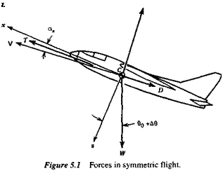
The a derivatives describe the changes that take place in the forces and moments when the angle of attack of the airplane is increased. They are normally an increase in the lift, an increase in the drag, and a negative pitching moment. The contents of Chap. 2 are relevant to these derivatives.

‘Since X and Z are the aerodynamic forces acting on the airplane, there are no weight components in

(5.1,1) .

Подпись: L

THE DERIVATIVE CXa

By definition, CXa = (ЭСх/Эа)0, where the subscript zero indicates that the derivative is evaluated when the disturbance quantities are zero. From (5.1,1)

dCx dCT dCL dCD

da da L x da da

Подпись: Cr Подпись: dCx da The a Derivatives (CXa, CZa, CmJ Подпись: dCo da Подпись: (5.2,1)

We may assume that the thrust coefficient is sensibly independent of ax so that dCT/da = 0, and hence

where the subscript zero again indicates the reference flight condition, in which, with stability axes, ax = 0. When the drag is given by a parabolic polar in the form CD = Cn + Cj/тгАе, then

b’min l – 7

Подпись:ЭCD _ 2CU. C’ Эа )0 7тАе ‘

THE DERIVATIVE CZa

Подпись: dC, da The a Derivatives (CXa, CZa, CmJ

By definition, CZa = (dCJda)0. From (5.1,1) we get

Therefore

cza= ~(CLa + CDo) (5.2,3)

CDo will frequently be negligible compared to CLa, and consequently CZa = — CLa.

THE DERIVATIVE C,„

a

Cma is the static stability derivative, which was treated at some length in Chap. 2. It is conveniently expressed in terms of the stick-fixed neutral point (2.3,25):

Cm,, = Ф ~ hn)

Подпись: (5.2,4)For airplanes with positive pitch stiffness, h<hn, and Cma is negative.