Category Dynamics of Flight

COMPUTATION OF EIGENVALUES AND EIGENVECTORS

As noted above, the eigenvalues and eigenvectors are properties of the matrix A. A number of software packages such as MATLAB are now available for calculating them. For all the numerical examples in this book we have used the Student Version of Program CC.1 Appendix A.5 shows how we used it to get the results.

ROUTH’S CRITERIA FOR STABILITY

The stability of the airplane is governed, as we have seen, by the real parts of the eigenvalues, the roots of the characteristic equation. Now it is not necessary actually to solve the characteristic equation (6.1,6) for these roots in order to discover whether there are any unstable ones. E. J. Routh (1905) has derived a criterion that can be ap­plied to the coefficients of the equation to get the desired result. The criterion is that a certain set of test functions shall all be positive (Etkin, 1972). We present below the result for the important case of the quartic equation, which will turn up later in this chapter.

Let the quartic equation be

AA4 + BA3 + CA2 + DA + £ = 0 (A>0) (6.1,13)

Then the test functions are F0 = A, F] = B, F2 = BC — AD, F3 = F2D — B2E, F4 =

Available from Systems Technology Inc. Hawthorne, CA.

F3BE. The necessary and sufficient conditions for these test functions to be positive are

A, B, D, E > 0

and

R = D(BC – AD) – B2E > 0 (6.1,14)

It follows that C also must be positive. The quantity on the left-hand side of (6.1,14) is commonly known as Routh’s discriminant.

Duncan (1952) has shown that the vanishing of E and of R represent significant critical cases. If the airplane is stable, and some design parameter is then varied in such a way as to lead to instability, then the following conditions hold:

1. If only E changes from + to —, then one real root changes from negative to positive; that is, one divergence appears in the solution (see Fig. 6.1a).

2. If only R changes from + to —, then the real part of one complex pair of roots changes from negative to positive; that is, one divergent oscillation appears in the solution (see Fig. 6.1c).

Thus the conditions E = 0 and R = 0 define boundaries between stability and in­stability. The former is the boundary between stability and static instability, and the latter is the boundary between stability and a divergent oscillation. These stability boundaries are very useful for certain analytical purposes. We shall in particular make use of the E = 0 boundary.

Form of Solution of Small-Disturbance Equations

The small-disturbance equations are (4.9,18 and 4.9,19). They are both of the form

x = Ax + Afc (6.1,1)

where x is the (А X 1) state vector, A is the (N X N) system matrix, a constant, and is the (N X 1) vector of incremental control forces and moments. In this applica­tion, the control force vector is zero, so the equation to be studied is

x = Ax (6.1,2)

Solutions of this first-order differential equation are well known. They are of the form

x(t) = x0eAr (6.1,3)

x„ is an eigenvector and A is an eigenvalue of the system. x0 is also seen to be the value of the state vector at t = 0. Substitution of (6.1,3) into (6.1,2) gives

Ax0 = Ax0

Подпись: (6.1.4) (6.1.5) or (A — AI)x0 = 0

where I is the identity matrix. Since the scalar expansion of (6.1,5) is a system of N homogeneous equations (zeros on the right-hand side) then there is a nonzero solu­tion for x0 only when the system determinant vanishes, that is, when

det (A — AI) = 0 (6.1,6)

The determinant in (6.1,6) is the characteristic determinant of the system. When ex­panded, the result is a polynomial in A of degree N, the characteristic polynomial, and the Mh degree algebraic equation (6.1,6) is the characteristic equation of the system. Since the equation is of the Mh degree it has in general N roots A„ some real and some occurring in conjugate complex pairs. Corresponding to each real eigen­value A is a real eigenvector x0, and to each complex pair A, and A* there corresponds a conjugate complex pair of eigenvectors x0 and xjj. Since any one of the A’s can pro­vide a solution to (6.1,2) and since the equation is linear, the most general solution is a sum of all the corresponding (t) of (6.1,3), that is,

x(0 =X xo, eA” (6.1,7)

І

Each of the solutions described by (6.1,3) is called a natural mode, and the general solution (6.1,7) is a sum of all the modes. A typical variable, say w, would, according to (6.1,7) have the form

w(t) = axex" + a2eK2′ + ••• (6.1,8)

where the а і would be fixed by the initial conditions. The pair of terms corresponding to a conjugate pair of eigenvalues

A = n ± ito (6.1,9)

is аІе, мНш)’ + a2e<-n~iw)‘ (6.1,10)

Upon expanding the exponentials, (6.1,10) becomes

en,(Ax cos cot + A2 sin cot) (6.1,11)

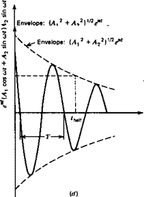
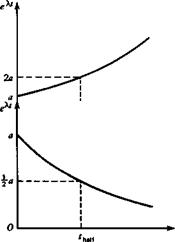
where A, = (a, + a2) and A2 = i(a] — a2) are always real. That is, (6.1,11) describes an oscillatory mode, of period T = 2ттІш, that either grows or decays, depending on the sign of n. The four kinds of mode that can occur, according to whether A is real or complex, and according to the sign of n are illustrated in Fig. 6.1. The disturbances shown in (a) and (c) increase with time, and hence these are unstable modes. It is conventional to refer to (a) as a static instability or divergence, since there is no ten­dency for the disturbance to diminish. By contrast, (c) is called dynamic instability or a divergent oscillation, since the disturbance quantity alternately increases and di­minishes, the amplitude growing with time. (b) illustrates a subsidence or conver­gence, and (d) a damped or convergent oscillation. Since in both (b) and id) the dis­turbance quantity ultimately vanishes, they represent stable modes.

It is seen that a “yes” or “no” evaluation of the stability is obtained simply from the signs of the real parts of the As. If there are no positive real parts, there is no in­stability. This information is not sufficient, however, to evaluate the handling quali-

Form of Solution of Small-Disturbance Equations

Figure 6.1 Types of solution, (a) A real, positive. (b) A real, negative, (c) A complex, n > 0. (d) A complex, n < 0.

ties of an airplane (see Chap. 1). These are dependent on the quantitative as well as on the qualitative characteristics of the modes. The numerical parameters of primary interest are

277

1. Period, T = —

0)

2. Time to double or time to half.

3. Cycles to double (/Vdoub|e) or cycles to half (NhM).

The first two of these are illustrated in Fig. 6.1. When the roots are real, there is of course no period, and the only parameter is the time to double or half. These are the times that must elapse during which any disturbance quantity will double or halve it­self, respectively. When the modes are oscillatory, it is the envelope ordinate that doubles or halves. Since the envelope may be regarded as an amplitude modulation,
then we may think of the doubling or halving as applied to the variable amplitude. By noting that log,, 2 = – loge = 0.693, the reader will easily verify the following rela­tions:

Подпись: ^double ^ hialf Подпись: .693 _ . 693 W kl ып Подпись: (a)

Time to double or half:

Form of Solution of Small-Disturbance Equations Form of Solution of Small-Disturbance Equations

Cycles to double or half:

In the preceding equations,

con = (со2 + n2)112, the “undamped” circular frequency £ = – n/co„, the damping ratio

Stability of Uncontrolled. Motion

The preceding chapters have been to some extent simply the preparation for what fol­lows in this and the succeeding two chapters, that is, a treatment of the uncontrolled and controlled motions of an airplane. The system model was developed in Chap. 4, and the aerodynamic ingredients were described in Chaps. 2, 3, and 5. In this chapter we tackle first the simplest of these cases, the uncontrolled motion, that is, the motion when all the controls are locked in position. An airplane in steady flight may be sub­jected to a momentary disturbance by a nonuniform or nonstationary atmosphere, or by movements of passengers, release of stores, and so forth. In this circumstance some of the questions to be answered are, “What is the character of the motion fol­lowing the cessation of the disturbance? Does it subside or increase? If it subsides what is the final flight path?” The stability of small disturbances from steady flight is an extremely important property of aircraft—first, because steady flight conditions make up most of the flight time of airplanes, and second, because the disturbances in this condition must be small for a satisfactory vehicle. If they were not it would be unacceptable for either commercial or military use. The required dynamic behavior is ensured by design—by making the small-disturbance properties of concern {the nat­ural modes) such that either human or automatic control can keep the disturbances to an acceptably small level. Finally the small-disturbance model is actually valid for disturbance magnitudes that seem quite violent to human occupants.

THE DERIVATIVE A„w

THE DERIVATIVE A„w

This derivative [see (4.12,12)] represents the contribution to the generalized force in the bending degree of freedom, associated with a change in the w velocity of the air­plane. A suitable nondimensional form is obtained by defining

and using ax in place of w (w = u0ax). Then the appropriate nondimensional deriva­tive is C&a.

Let the wing lift distribution due to a perturbation a in the angle of attack (con­stant across the span) be given by Cta{y)a. Then in a virtual displacement in the wing bending mode 8zT, the work done by this wing loading is

(ьп 1 „

Подпись: -Ы2 l

SW = — aC, Jy)h(y) 8zT — purely) dy

where c(y) is the local wing chord. The corresponding contribution to 2F is

and to C9a is

THE DERIVATIVE A„w(5.10,6)

THE DERIVATIVE A„w

The tail also contributes to this derivative, for the tail lift associated with a is

and the work done by this force during the virtual displacement is

THE DERIVATIVE A„w—a, a

THE DERIVATIVE A„w

Therefore the contribution to C, f is

and to C9a is

THE DERIVATIVE A„w(5.10,7)

The total value of C$n is then the sum of 5.10,6 and 5.10,7.

THE DERIVATIVE bu (see 4.12,12)

This derivative identifies the contribution of zT to the generalized aerodynamic force in the distortion degree of freedom. We have defined the associated wing load distri-

THE DERIVATIVE A„w

bution above by the local lift coefficient Cfy)zT/u0. As in the case of the derivative Anw above, the work done by this loading is calculated, with the result that the wing contributes

5.7 Exercises

5.1 THE DERIVATIVE A„wПодпись: Estimate the magnitude of this termThe derivative C, u contains the term M0

for an airplane with wing loading 70 psf (3,352 Pa) flying at 20,000 ft (6,096 m) alti­tude, for Mach numbers between 0.2 and 0.8. The following data pertain to the wing:

Sweep (i chord) Л = 30°

S= 5,500 ft2 (511.0 m2)

Plot the result vs. M0. Calculate the contribution this term makes to Z„ and plot this as well. (Compare with Zu for the B747 from Table 6.2, and comment).

5.2 A wind-tunnel model is mounted with one degree of freedom-pivoted so that it can only rotate about the у-axis of the body frame, which is perpendicular to the relative wind. It is elastically restrained with a pitching moment M = —кв. Show how the sum (C,„_( + C,„.) can be estimated from experiments in which the model is free to os­cillate in pitch with wind on and off. Assume Mq can be neglected with the wind off and Zq and Zi;. can be neglected.

5.3 Consider the wind/fin system of Fig. 5.16, with the following properties:

Wing: A = 5; A = 0.5; A1/4 = 30°; Г variable

Fin: aF = 3.5 rad-1; lF/b = 0.5; zF/b = 0.1; Vv variable; Эгг/Э/3

negligible.

Estimate values of the stability derivatives (for hnw = h and L/D =12)

c c c c

Wp» ^/r» ^nr

at CUt = 1.0. Plot the spiral stability boundary for horizontal flight:

E — ClrC„, — ClrC,41 = 0

[see (6.8,6) with в0 = 0] in the plane of Vv vs. Г. (Make any reasonable assumptions you need to supplement the given data).

5.4 A jet airplane has a thrust line that passes above the CG by a distance equal to 10% of the M. A.C. With the assumption дТ/ди = 0, estimate the increment thus caused in

a‘ b

Подпись: 5.5 Find Cn due to the tilting of the lift vector for a wing with an elliptic lift distribution ' l2 4/ i.e., a wing with lift per unit span l(y) which obeys —j H j- = 1 ]. Assume that the tilt angle is small. Express СПр in terms of CL, the lift coefficient of the wing when it is not rolling.

5.6 Assume that Figs. 5.7 and 5.8 are experimental measurements. Select an analytic function CLaJt) that can represent Fig. 5.7 (M = 0 case). Find the corresponding transfer function relating CL to a. Use this transfer function to generate a function of time corresponding to Fig. 5.8b and demonstrate that it has the desired form.

FORCES ON THE WING

The vertical velocity of the wing section distant у from the center line is

z = h(y)zT (5.10,2)

and the corresponding change in wing angle of attack is

Да(у) = h(y)zTfUf) (5.10,3)

This angle of attack distribution can be used with any applicable steady-flow wing theory to calculate the incremental local section lift. (It will of course be proportional to t/JUfy) Let it be denoted in coefficient form by C’j(y)zT/u0, and the corresponding increment in wing total lift coefficient by C’LJzTlu0. CJ(y) and C’u are thus the values corresponding to unit value of the nondimensional quantity zT/u0.

FORCE ON THE TAIL

The tail experiences a downward velocity h(0)zT, and also, because of the altered wing lift distribution, a downwash change (Эе/Эіт)іт – Hence the net change in tail an­gle of attack is

Эе

Да, = h(0)zT/uo – іт

OZf

Г Й£ 1 Zr

= m – —— —

diXjiW0) J Uq

Подпись: Д C,
FORCES ON THE WING Подпись: ZT_ u0 Подпись: (5.10,4)

This produces an increment in the tail lift coefficient of amount

THE DERIVATIVE Z,

ZT

Подпись: ZT Д Cz=-Cl —-a, Подпись: MO) FORCES ON THE WING Подпись: ZT

This derivative describes the contribution of wing bending velocity to the Z force act­ing on the airplane. A suitable nondimensional form is dCz/d(zT/u0). Since Cz = —CL, we have that

Подпись: d(zT/u0) Подпись: ' ^ U at Подпись: M 0) FORCES ON THE WING Подпись: (5.10,5)

and hence

Aeroelastic Derivatives

In Sec. 4.12 there were introduced aerodynamic derivatives associated with the defor­mations of the airplane. These are of two kinds: those that appear in the rigid-body equations and those that appear in the added equations of the elastic degrees of free­dom. These are illustrated in this section by consideration of the hypothetical vibra­tion mode shown in Fig. 5.17. In this mode it is assumed that the fuselage and tail are rigid, and have a motion of vertical translation only. The flexibility is all in the wing, and it bends without twisting. The functions describing the mode (4.11,1) are there­fore:

jc’ = 0

У’ = 0 (5.10,1)

z’ = h(y)zT

For the generalized coordinate, we have used the wing-tip deflection zT. h(y) is then a normalized function describing the wing bending mode.

Since the elastic degrees of freedom are only important in relation to stability and control when their frequencies are relatively low, approaching those of the rigid – body modes, then it is reasonable to use the same approximation for the aerodynamic forces as is used in calculating stability derivatives. That is, if quasisteady flow the­ory is adequate for the aerodynamic forces associated with the rigid-body motions, then we may use the same theory for the elastic motions.

Aeroelastic Derivatives

Figure 5.17 Symmetrical wing bending.

In the example chosen, we assume that the only significant forces are those on the wing and tail, and that these are to be computed from quasisteady flow theory. In the light of these assumptions, some of the representative derivatives of both types are discussed below. As a preliminary, the forces induced on the wing and tail by the elastic motion are treated first.

Summary of the Formulas

The formulas that are frequently wanted for reference are collected in Tables 5.1 and

5.2. Where an entry in the table shows only a tail contribution, it is not implied that the wing and body effects are not important, but only that no convenient formula is available.

The r Derivatives (Cyr, Clr, СПг)

Подпись: or The r Derivatives (Cyr, Clr, СПг)

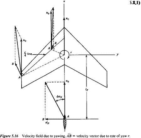
When an airplane has a rate of yaw r superimposed on the foward motion u0, its ve­locity field is altered significantly. This is illustrated for the wing and vertical tail in Fig. 5.16. The situation on the wing is clearly very complicated when it has much sweepback. The main feature however, is that the velocity of the chord line normal to itself is increased by the yawing on the left-hand side, and decreased on the right side. The aerodynamic forces at each section (lift, drag, moment) are therefore in­creased on the left-hand side, and decreased on the right-hand side. As in the case of the rolling wing, the unsymmetrical lift distribution leads to an unsymmetrical trail­ing vortex sheet, and hence a sidewash at the tail. The incremental tail angle of attack is then

THE DERIVATIVE Cyr

The r Derivatives (Cyr, Clr, СПг) Подпись: - /0 IF da a”rY 2T + IF

The only contribution to СУг that is normally important is that of the tail. From the an­gle of attack change we find the incremental Cy to be

thus

Подпись: (Cyr)tail aF cПодпись: da dr The r Derivatives (Cyr, Clr, СПг)(5.8,2)

THE DERIVATIVE Clr

This is another important cross derivative; the rolling moment due to yawing. The in­crease in lift on the left wing, and the decrease on the right wing combine to produce a positive rolling moment proportional to the original lift coefficient CL. Hence this derivative is largest at low speed. Aspect ratio, taper ratio, and sweepback are all im­portant parameters.

When the vertical tail is large, its contribution may be significant. A formula for it can be derived in the same way as for the previous tail contributions, with the result

Sf? Zf I Ip da

«y.„ = «,T17(2T + 1f) <5ад

THE DERIVATIVE C„r

C„r is the damping-in-yaw derivative, and is always negative. The body adds a negli­gible amount to Cnr except when it is very large. The important contributions are those of the wing and tail. The increases in both the profile and induced drag on the left wing and the decreases on the right wing give a negative yawing moment and hence a resistance to the motion. The magnitude of the effect depends on the aspect ratio, taper ratio, and sweepback. For extremely large sweepback, of the order of 60°, the yawing moment associated with the induced drag may be positive; that is, pro­duce a reduction in the damping.

The side force on the tail also provides a negative yawing moment. The calcula­tion is similar to that for the preceding tail contributions, with the result

( If da

(CJtail = ~aFVv (2- + —) (5.8,4)

THE DERIVATIVE C„

The yawing moment produced by the rolling motion is one of the so-called cross de­rivatives. It is the existence of these cross derivatives that causes the rolling and yaw­ing motions to be so closely coupled. The wing and tail both contribute to Cn .

The wing contribution is in two parts. The first comes from the change in profile drag associated with the change in wing angle of attack. The wing a is increased on the right-hand side and decreased on the left-hand side. These changes will normally be accompanied by an increase in profile drag on the right side, and a decrease on the

THE DERIVATIVE C„

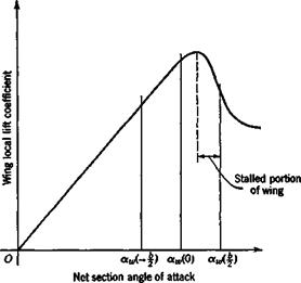
Figure 5.14 Reduction of C, due to wing stall.

THE DERIVATIVE C„

У

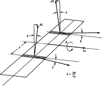
Figure 5.15 Inclination of CL vector due to rolling.

left side, combining to produce a positive (nose-right) yawing moment. The second wing effect is associated with the fore-and-aft inclination of the lift vector caused by the rolling in subsonic flight and in supersonic flight when the leading edge is sub­sonic. It depends on the leading-edge suction. The physical situation is illustrated in Fig. 5.15. The directions of motion of two typical wing elements are shown inclined by the angles ± в = py/u0 from the direction of the vector u0. Since the local lift is perpendicular to the local relative wind, then the lift vector on the right half of the wing is inclined forward, and that on the left half backward. The result is a negative yawing couple, proportional to the product CLp. If the wing leading edges are super­sonic, then the leading-edge suction is not present, and the local force remains nor­mal to the surface. The increased angle of attack on the right side causes an increase in this normal force there, while the opposite happens on the left side. The result is a positive yawing couple proportional to p.

THE DERIVATIVE C„

The tail contribution to СПр is easily found from the tail side force given previ­ously (5.7,2). The incremental C„ is given by

THE DERIVATIVE C„

where lF is the distance shown in Fig. 3.12. Therefore

Подпись: and

THE DERIVATIVE C„

(5.7,4)

where Vv is the vertical-tail volume ratio.