Category Helicopter Test and Evaluation

AFCS failures

The evaluation of failures within flight control systems is of particular importance because of the potential that these failures have to disturb the flight path of the helicopter. As flight control systems are fitted to provide additional stability and, in the case of autopilots, to control the aircraft they must have sufficient authority to make large enough inputs. Thus the AFCS designer is faced with balancing two conflicting requirements: high performance and benign failure characteristics. Of course one way of achieving both is to design the system with triplex or quadruplex redundancy and voting logic. This approach does suffer disadvantages in terms of complexity and cost that often make it unattractive for limited authority AFCSs. For these simpler systems the more usual solution is to employ simplex or duplex limited authority, fast-acting series actuators and high authority, slow-acting parallel actuators. Consequently the failure testing of these classes of AFCS is primarily concerned with evaluating the effect that failures may have on both series and parallel actuators and hence on the flight path of the aircraft.

There are a number of different types of failure that can occur within an AFCS and it is convenient to divide these into active and passive failures. The active failures are those that cause an uncommanded flight path disturbance while passive failures involve a loss of function but no disturbance. Active failures are clearly the more serious of the two and this category can be further sub-divided into oscillatory failures and runaways. Oscillatory failures are usually caused by problems with the feedback path that results in the actuator constantly reversing direction. Runaways may have many causes such as failures within the computation or erroneous sensor signals. It goes without saying that a series actuator runaway can be particularly hazardous should it occur in an agile aircraft that is flying close to the ground at high speed. Although passive failures are likely to be far less dramatic they can still lead to potentially catastrophic consequences. For example, if a radar altimeter hold drops out when operating at night, low level over the sea there is a considerable danger of the aircraft descending unnoticed and striking the surface.

7.6.6.1 Test technique

The main factors that influence the way the pilot reacts to the failure are the recognition that something has occurred and the level of involvement of the pilot in the flying task. From these two factors the desired intervention time is determined as has been discussed earlier. The test philosophy centres on injecting appropriate failures and incrementally increasing the intervention time until the specification requirements have been met or a limit is reached. The testing starts with practise of recoveries from extreme pitch and roll attitudes; this is approached cautiously as it is often the case that the highest stresses experienced by the airframe occur during the recovery and not during the runaway itself. If a simulator is available this can be useful in working up the crew. Failures are typically injected into the AFCS using a ‘runaway box’ starting at the most benign conditions of low speed, mid-CG and series actuators nulled (for dual lane systems). The testing then moves on to evaluate less benign conditions. In the case of actuator runaways the pilot is usually given an aircraft attitude at which to commence recovery: this is gradually increased until the required intervention time has been achieved or a test limit is reached. During the test plots of the intervention pitch (or roll) attitude versus maximum attitude and maximum load factor are maintained. For pitch runaways it is important to establish the height change that results from the full intervention time at each condition and in particular the height loss for forward runaways. During the test programme the utility of any AFCS cutout is assessed and the optimum strategy for recovery from runaways established. Cutouts may serve a variety of functions: to temporarily disengage part or all of the AFCS as and when a failure is recognized, to enable fault diagnosis and to re-engage serviceable parts of the system following a single failure.

7.6.6.2 Results of testing

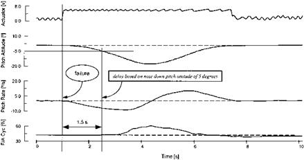
Figure 7.18 shows a time history of a pitch runaway. Such traces are a typical way of presenting results. The results obtained during the test programme can have a number

image197

Fig. 7.18 Pitch series actuator runaway – test data.

of implications for the AFCS and for the way that the aircraft is operated. In the worst case it may require changes to the design of the system such as altering the speed or authority of the actuators. Making the system more fault tolerant by fitting a monitor channel which automatically disengages a faulty lane is another possible solution to unsatisfactory failure characteristics. More often the test programme will result in advice to aircrew and limitations on the use of the system. Such advice might stress the importance of timely and accurate nulling of the series actuators prior to NOE flight or operations close to the sea surface. Alternatively a deliberate forward bias of the series actuators may be obtained by trimming forward thereby reducing the severity of a nose-down runaway. Limitations that could be imposed include maximum speeds with the full AFCS and when operating with a degraded system. It might also be necessary to impose a minimum height for NOE flight if the height loss following a nose-down runaway is too great. The need for operational crews to practise recoveries from runaways may also be a recommendation from the testing. This may lead to a production version of the flight test ‘runaway’ box being incorporated into all fleet standard rotorcraft.

[1] undercarriage type – wheeled or skidded;

• available stroke in undercarriage – main and tail/nose;

• crashworthiness of cockpit, fuselage floor or cabin and fuel system;

• tail boom strength;

• field of view;

• rotor inertia.

[2] Conduct a hover (H1) at the altitude (Hp1) giving the highest desired referred weight (W1) and establish the hover power.

(2) Descend and establish H2 at Hp2 ( = Hp1 — 500 ft) and W2.

(3) Set maximum power and conduct MPV1, timing the ROC in the altitude band Hp1 —100 ft to Hp1 + 300 ft. The extra 100 ft allows for a small increase in Hp to compensate for the fuel burned between H1 and MPV1 in order to maintain W1 .

(4) Descend and establish H3 at Hp3 ( = Hp2 — 500 ft) and W3. Conduct MPV2 as above.

(5) Repeat the process until the desired data is acquired.

[3] Pressure altitude;

• Elapsed time;

• Indicated airspeed;

• Fuel state;

[4]yy

[5] Disturbance along the longitudinal axis. Suppose the rotor is subjected to a disturbance equivalent to the rotor developing a forward airspeed component. When the disturbance appears the hovering rotor develops an asymmetry in tangential velocity and subsequent change in AOA and lift: more on the advancing side (A) and less on the retreating side (R).

[6] Disturbance along the vertical axis. If the rotor develops a sink rate the inflow velocity component is reduced and the AOA consequently increased. Since the rotor is in pure vertical flight the increase in lift, arising from the increase in AOA, will be equally distributed around the azimuth.

[7] Change in blade pitch. Suppose the rotor is disturbed such that the swash plate is moved instantly and the rotor attitude is initially unchanged. (This disturbance mode is an important case in considering the manoeuvre stability of a helicopter.) If the swash plate is tilted nose-up (positive direction) an increase in blade pitch

[8] SHSS technique – GSDIfitted aircraft. The helicopter is flown into wind with zero roll angle and slipfall central (GSDI drift needle reading zero) and aircraft head­ing is noted. The helicopter is then yawed to change heading by the sideslip angle required while maintaining the aircraft track into wind. The GSDI drift needle should indicate the change in sideslip angle and, if the correct flight path has been maintained, this value will give a working approximation of sideslip angle.

[9] SHSS technique – non-GSDIfitted aircraft. The helicopter is flown down a line feature (a runway) into wind and aircraft heading is noted. The helicopter is then yawed to change heading with zero roll angle and slipfall central by the sideslip angle required while maintaining aircraft track down the line feature.

[10] The cyclic is deflected out ofthe turn, that is towards the left (Al positive), therefore Lr. r > Lv. v and the yaw rate contribution is dominant.

• The cyclic is deflected into the turn (Al negative), thus Lr. r < Lv. v and the sideslip contribution is dominant.

[11] Desired performance. This is the highest level of performance and is awarded when the desired tolerance is achieved with a satisfactory pilot workload. No improvement in handling qualities is required therefore (HQR 1-3).

• Adequate performance. In this category either the desired tolerance is achieved but with an unsatisfactory level of pilot workload (HQR 4) or the adequate tolerance is achieved with a tolerable level of workload (HQR 5 & 6). An improvement in handling qualities is warranted.

[12] Light engine weight. To obtain a given power output, the gas turbine engine will normally be much lighter than the corresponding piston engine. This advantage is extremely important since it allows smaller turbine engined helicopters to do

[13] The governor should maintain a sensibly constant RRPM under all power-on conditions. When required the governor should prevent the free turbine from overspeeding. At the same time the governor should be free from NF/NR instability at low collective pitch settings over the whole range of possible helicopter all-up weights.

• The response of the engine and/or free turbine governing system should be quick enough to maintain the RRPM (NR) within limits during large, rapid power changes.

• The governor should be capable of providing stable control at all times notwith­standing that the engine might be ON or OFF load.

• In multi-engine installations, individual engine governors must be so configured that power matching can be achieved easily and consistently throughout the power range.

[14] To align the tailplane with the rotor downwash in low speed flight in order to improve performance, reduce the nose-up hover attitude and to reduce the tendency to pitch-up during transitions to forward flight.

[15] Rotor acceleration. The appropriateness of the acceleration schedule is checked to ensure that it does not lead to the aircraft yawing on icy or wet dispersals.

• System stability. Due to the high system gain a danger of instability exists in addition to the danger of drivetrain resonance already discussed. Collective doublets and frequency sweeps are made to assess these areas.

[16] Radar altimeter height holds. Because these holds are employed close to the surface and often in a degraded visual environment they require particularly careful evaluation. The accuracy requirements for this type of hold are always more stringent than for barometric height holds. To quote from the same UK military helicopter specification mentioned previously the radar height hold required the height to be maintained to the lesser of 10% or 10 feet. As radar height holds are usually employed in overwater operations testing is conducted with a variety of sea states at a variety of airspeeds and angles of bank. The testing takes place at heights that are operationally relevant; this can be as low as 40 feet in the case of anti-submarine helicopters. If a smoothing circuit is incorporated to deal with wave peaks and troughs then its effectiveness in operation is checked by comparing the performance of the hold when using the raw signal. Careful evaluation is made of the radar altimeter failure modes and the indications to the pilot if the altimeter unlocks.

• Vertical speed holds. These are assessed by selecting RoC and RoD and then timing the aircraft through an altitude band. In an autopilot where the mode operates through the collective channel then the danger of the system causing an excessive power demand is investigated and limitations may be imposed. Similarly a minimum airspeed is always imposed on three-axis systems which hold vertical speed through the pitch channel to prevent the hold operating on the wrong side of minimum power speed. The ease with which the system captures the selected

Failure cueing

Engineering an effective engine failure warning in a multi-engine installation can be a difficult task. Some systems are triggered by low oil pressure as the engine-driven pump slows down but these systems often suffer from significant delays. Another approach is to compare the power output of the engines and trigger the warning if the difference exceeds a threshold value. This type of system can be problematic if the power-sharing characteristics of the engine governors are not well matched.

7.6.5.4 Sudden engine failures

As is the case with single-engine machines the aim of sudden engine failure testing in forward flight is to establish the intervention time available and to check that there are no handling implications. Testing in the low speed flight regime is also required to establish the aircraft performance and to determine the optimum techniques for landing or achieving a safe flight condition. The intervention time is established using rotor speed as the controlling parameter in much the same manner as for total power loss testing. In a multi-engine installation the rotor speed decay rate will be clearly much slower, however, an incremental approach is equally important. The same range of parameters will affect this rate of decay as for the single-engine helicopter discussed in Section 2.12. In addition the acceleration characteristics of the functioning engine will have an effect as the faster the engine acceleration the slower the NR decay will be. As described before sudden engine failures should be made in level flight starting at VMP and then progressing to selected speeds throughout the flight envelope. It may also be necessary to conduct failures at the combination of speed and power normally used for climbing flight.

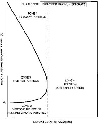
The most critical area for powerplant failures and hence for testing is in the hover and low speed regime. Here the testing is used to establish the techniques for conducting flyaways and vertical or forward rejects. Advice to operational crews is given in the form of a height/velocity diagram in the same way as is done for single-engine aircraft. Figure 7.14 shows an example of an avoid curve that has been produced as a result of this type of testing. The diagram is divided into four zones defined by height and airspeed. The important area is Zone 3: in this zone the aircraft is not able to perform a flyaway and a safe vertical or forward reject is also not possible. It should be remembered that the avoid curve may be sized on the assumption that at the boundary

image193

Fig. 7.14 Height/velocity diagram for a multi-engine helicopter.

a given level of aircraft damage may occur. The combination of height and speed from which a vertical or forward reject is possible depends mainly on the rotor decay characteristics for the test conditions and the energy-absorbing properties of the undercarriage. During the tests the rate of descent is kept within the undercarriage design limits and the minimum NR is noted. The results are often compared with the predictions of any model used as part of the planning and risk assessment so that the model may be used to generate the advice given to operational crews.

For flyaway testing a model can be used to determine the optimum technique to be used to minimize height loss and one of the aims of the test programme is to establish if the technique is easy and repeatable to fly. If no model is available or the manufacturer fails to recommend a technique then a variety of flyaway profiles will have to be tried to establish the best method. The difficulty of flying any proposed technique must be borne in mind as the operational pilot will not be expecting a failure and will not be as adept or practised as the test pilot(s) conducting the trial. Accurate trends and therefore meaningful predictions can only be made if the chosen technique is flown consistently. At some point, however, it is often necessary to conduct testing to determine the sensitivity of the avoid curve data to a non-optimum technique.

Once the flyaway technique has been established testing starts by determining that the specified intervention time is achievable in the hover. For this the aircraft is hovered well clear of the ground and the flyaway profile practised. Initially the engine failure is coupled with a simultaneous flyaway. Then the intervention time is gradually increased by the pilot reacting to the failure at lower values of rotor speed (NR1). Once the NR1 that equates to the required intervention time has been found it is used for the remainder of the hover flyaway testing. The total height loss suffered between the failure and the achievement of a safe flight condition is recorded as this can be used in defining the initial height AGL for the tests nearer the ground. It has been found from personal experience that the height loss during a flyaway is affected to a large extent by the initial hover height. The stronger visual cues to pitch attitude and RoD at lower heights assist the pilot in flying the manoeuvre and so help to reduce the height loss. To find the height loss near the ground the hover height used is reduced incrementally until consistent results are achieved with realistic visual cues. Typically a minimum height of 50 feet AGL is set for the recovery and the failure height set to ensure this limit is respected.

There are a number of risk reduction measures that are taken with this type of testing. As already stated an accurate predictive model reduces the chances of unpleasant surprises. Where possible two crew members are carried and the flight monitored by telemetry. It is worth noting again that for hydro-mechanical fuel control systems experience has shown that if cockpit controls are used to ‘top’ an engine, airframe vibration can cause the control to move. For this reason the power output of the ‘good’ (non-failed) engine requires careful monitoring to ensure that the settings remain unchanged. This can be achieved by reviewing the telemetry traces immediately after each test to check that when the maximum available power was demanded the torque, engine speed, and temperature figures did not drift from those seen on the previous test point. Risk to the aircraft and crew can also be mitigated if there is a procedure for rapidly restoring the engine under test and the ‘failed’ engine to full performance if needed. This may involve detailed discussions with the manufacturer and could lead to a non-standard engine handling methodology. Of equal importance is to have a single command such as ‘Abort!’ which can be issued by any member of the crew, or the observer in telemetry, to restore the engines and achieve a safe flight condition. Finally if cockpit controls have been used to limit an engine then the non­flying crew member keeps his or her hands on the relevant engine controls at all times.

OEI testing for civil procedures is in many respects the same as for military requirements, however, the aims of the test programme are slightly different and this is particularly true for the take-off and landing phases of flight. In military operations it is accepted that the aircraft may spend periods where an engine failure would place the aircraft at risk. The results of testing are therefore used to determine the level of risk for a typical mission. In addition information is produced which lets the operational pilot know where the risk lies (the height/velocity diagram) and which techniques can be used to avoid or minimize damage if a failure does occur. The military pilot can then make an informed judgement on how the aircraft should be operated. Civil operations have a different philosophy. When operating to JAR-29 Category A requirements [7.11] there is an intention that passengers are not placed at significant risk in the event of any failure including the powerplants. The overall aim of the civil OEI test programme then is to determine the boundaries of safe operation. This is achieved by establishing limiting combinations of AUM and density altitude at which passenger safety is assured provided the pilot performs the reject or flyaway in the prescribed manner. The estimation must include a suitable delay time to account for pilot recognition of a failure of the most critical engine (JAR-29.55 and 29.77). It

image194

Fig. 7.15 Normal take-off – JAR Category A requirements.

image195

Fig. 7.16 Engine failure during take-off – JAR Category A procedures.

is worth examining the way that civil operators deal with the two most critical flight phases – take-off and landing.

Figure 7.15 shows a typical technique for conducting a normal take-off under Category A conditions. From a low IGE hover, with the height set such that following an engine failure the aircraft could descend vertically at a rate below the limit for the landing gear, the pilot applies take-off power and starts a climbing acceleration. The take-off decision point (TDP) is usually reached when the aircraft is slightly higher and has positive airspeed indications, typically 30 KIAS. The TDP is defined as the first point from which a continued take-off is assured and the last point from which a rejected take-off is assured within a specified distance (JAR-29.55). Different take-off techniques are often prescribed for different scenarios: short runways, confined areas or helipads and it is common practice for a manufacturer to specify a reduction in the maximum permitted AUM and HD as the take-off area gets smaller and more congested. Once the TDP has been passed the aircraft is accelerated to take-off safety speed (ETOss) and then on to the speed for best rate of climb (Vy).

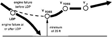
Figure 7.16 shows a typical flight path for an engine failure before or at the TDP and for a failure after the TDP in VFR conditions. In the first case an aborted take­off is performed by reducing speed and landing on. For a failure after the TDP the aircraft is quickly accelerated to achieve VTOSS. This speed is then held until the height has increased to at least 200 ft (JAR-29.59) before the speed is increased to Vy.

The approach to landing is treated in a similar way. In Fig. 7.17 flight paths for an engine failure either side of the landing decision point (LDP) are depicted. The LDP is the last point in the approach and landing path from which a baulked landing can be performed (JAR-29.77). During the aborted approach the aircraft may not descend below 35 ft at any time.

For both take-off and landing under Category A flight the civilian pilot is required

image196

Fig. 7.17 Engine failure during landing – JAR Category A procedures.

to consult the aircraft flight manual to determine the aircraft performance. As indicated above the information is likely to include:

• maximum permissible take-off and landing weights;

• rate of climb with one engine inoperative;

• the acceleration/stop distance;

• distance to clear a 50 ft obstacle with an engine failure at the TDP;

• landing distance for an engine failure after the LDP.

The aim of civilian OEI testing is to determine the optimum technique and combination of heights AGL and speeds for conducting these take-offs and landings. In addition the helicopter performance will be noted so that the appropriate information regarding maximum weights can be presented in the flight manual. The test procedures used are closely related to those that have already been covered, however, a more detailed examination of the techniques used to determine the TDP is worthwhile.

For establishing the TDP the critical engine is ‘failed’ at a height and speed which allows the 35 ft minimum height to be respected easily. The height and speed are then incrementally reduced until either the TDP predicted by a model is reached or the minimum 35 ft ground clearance is just achieved. It is worth reiterating the ‘golden rule’ that only one parameter should be varied at a time. The next stage is to conduct a series of aborted take-offs starting at low height and speed and incrementally working towards the TDP established from the previous tests. It is mandated (JAR – 29.55) that the TDP is easily recognizable by the pilot in terms of height and/or speed. Using speed alone can often be problematical due to the poor performance of most pitot systems at low speeds.

Engine failures in multi-engine helicopters

7.6.5.1 Conduct of the test programme

A great deal of preparation is needed before the trials programme can start. A detailed knowledge of the engines and transmission system is essential. This should allow appropriate testing without unnecessary damage to the aircraft and powerplants. It may be necessary to approach the engine and airframe manufacturers for concessions to the normal limitations. Some thought has to be given to planning how the power failure is to be simulated and, most importantly, how the power output of the engine (or engines) which is not being ‘failed’ is restricted so that it is representative of a minimum specification engine. For hydro-mechanical fuel control systems this may be achieved by manually restricting the fuel flow using the normal engine controls in the cockpit or it may require modifications to the engine governing system itself. With FADEC systems it is often necessary for the manufacturer to provide a software ‘patch’ which causes the engine to operate at minimum specification power. Whichever way the required power output is achieved, trials risk is minimized if there is a method of rapidly restoring the power to its maximum value. It is vital to monitor the power output of the ‘good’ engine during the trial, particularly during the flyaway/vertical reject phase as it has been known for vibration to cause the cockpit controls to drift and reduce the available power.

The choice of which engine to ‘fail’ is an interesting question. During OEI testing on the triple engined Westland/Agusta EH 101 the choice was between the No. 1 and No. 3 engines as the central No. 2 engine suffered an extra 2% installation power loss in the hover under sea-level-ISA conditions. The No. 1 engine was eventually chosen when it was discovered that there was a further power loss on the No. 2 engine as the No. 1 ran down through ground idle and its exhaust gases were ingested through the No. 2 engine intake.

7.6.5.2 Post-failure performance and handling

The flight trials commence with an evaluation of the aircraft performance and handling with one engine inoperative (OEI). Initially one engine is throttled back in level flight at the speed for minimum power and the aircraft handling is checked. The next stage is to shut down one engine. This should take place at VMP just in case there is any effect on the power available from the other engine(s). The minimum and maximum speeds in level flight that can be sustained on the good engine(s) are found together with the maximum sustainable angle of bank. It may be necessary to conduct a full level flight performance test to determine the power required and fuel flow for a range of airspeeds. This information is then often incorporated into the performance manual for use by operational crews. Once the performance has been established a series of gentle manoeuvres is made to determine if there are any handling problems. This whole process is then repeated at higher altitudes.

7.6.5.3 Engine re-lights

To achieve a successful engine start the mass flow of air through the compressor must be sufficient to achieve self-sustaining operation whilst preventing excessive turbine entry temperatures. At high altitudes the air density may be too low for a start to be achieved. This usually results in a re-light envelope that is smaller than the operational envelope of the helicopter. Since the air temperature affects density the re-light envelope is often expressed in terms of density altitude along with airspeed as this can affect conditions at the engine inlet. Testing of engine re-lights commences at low altitude and a mid-speed range and will then go on to expand the envelope in terms of density altitude and airspeed. In addition to establishing the envelope the testing also encompasses the effect that engine starting has on other aircraft systems. For example, the load on the electrical system may be such that the AFCS is affected or navigation equipment disrupted. Clearly if engine start is achieved using bleed air from another engine the effect of a start on the functioning engine requires assessment.

Engine-off landing tests

The aim of engine-off landing tests varies depending on the role of the aircraft. In the case of helicopters without a training role the aim is usually to prove that a safe landing is possible and to offer some advice in the aircrew manual. For aircraft with a training role where EOLs are likely to be commonplace a much more comprehensive series of tests is needed. The aim of these tests is usually to establish a box defined in terms of the airspeed and height at which the initial flare should be started. Within the box the handling qualities will be such that a student pilot can perform an EOL without undue skill; clearly the larger the box the more suitable the helicopter will be for teaching the skills required for engine-off landings.

The tests commence using the speed for minimum ROD in autorotation and a flare height determined from the powered recovery tests. Although the co-pilot makes a call at a pre-determined height on the radar altimeter, the responsibility for choosing when and how to perform the manoeuvre always rests with the handling pilot. The next point is then flown keeping the airspeed the same but changing the flare height. For each combination of speed and height the pilot rates the difficulty of the manoeuvre taking into account such things as predictability of the touchdown point, rotor speed control, proximity of the tail to the surface, touchdown speed and control margins. A series of these tests then allows construction of the box. At no stage is a point attempted that has a combination of an untried flare height and untried airspeed. Wind velocity, aircraft AUM and density altitude all affect the manoeuvre and therefore the power-off landings programme starts with the most favourable conditions and then moves incrementally to the least favourable.

7.6.4.4 Avoid area testing

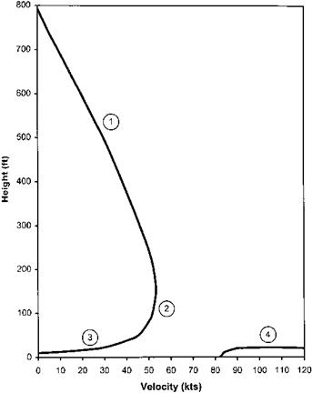
The final stage of a power-off assessment programme is to define the avoid curve, avoid area or height/velocity diagram. An example of the type of presentation commonly seen in aircrew manuals is shown in Fig. 7.13. An avoid area diagram shows the operational pilot the combinations of airspeed and height above the surface from which a total loss of power is unlikely to be survivable. Armed with this information the pilot can plan the aircraft’s flight path to minimize the time spent at risk inside the area. A number of assumptions are normally made in the construction of height/ velocity diagrams:

• The aircraft is in level flight or the hover at the moment of power loss.

• There is a total intervention delay time of 2 seconds.

• There is no wind and the surface is suitable for a landing.

It is common practice to present different charts for sea level and a higher density altitude (in the region of 5000 feet); similarly several charts can be produced to account for variations in aircraft AUM.

The height/velocity diagram can be divided into four areas indicated as 1 to 4 on Fig. 7.13. Area 1 is dictated by the height loss required to achieve an autorotative

image192

Fig. 7.13 Typical height/velocity diagram.

state and to accelerate the aircraft to an airspeed where an effective flare can be made. In Area 2 around the knee of the curve, the aircraft will not develop steady autorotation nor will a significant increase in airspeed be possible. Here the pilot will only be able to level the pitch attitude and use the remaining energy in the rotor to cushion the landing. Area 3 is dictated by the energy-absorbing qualities of the undercarriage and the rotor inertia. Area 4 needs to be avoided to allow sufficient height for the pilot to perform a flare to reduce groundspeed.

Performing avoid area testing carries with it a high level of risk which is mitigated by using test pilots who are fully familiar with the power-off landing characteristics of the aircraft being tested. Of course the standard risk reduction method of approaching each test point incrementally is applied rigorously in these trials. Testing starts from a known and benign point, for example, 500 ft and 60 KIAS; the height is then kept constant and the speed reduced by a small amount (5 to 10 kts) and another failure is simulated. After each landing the pilot awards a difficulty rating or an HQR. This process is repeated using small reductions in airspeed until the test pilot judges that the difficulty of performing the landing is such that following a sudden engine failure an operational pilot would not be able to achieve a survivable touchdown. For the testing of the low height points in Areas 3 and 4 the airspeed is kept constant and the height is incrementally increased or decreased as appropriate. It is a strict rule that only one parameter is varied between one test point and the next; these parameters include airspeed, height, wind velocity and direction, density altitude, AUM, aircraft configuration, intervention time and finally the individual test pilot.

Entries into autorotation with delay times

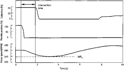
A vital part of the test programme is to determine the delay time (intervention time) that is possible between an engine failure occurring and the pilot lowering the collective. As explained earlier the intervention time is made up from the rotorcraft response time and the pilot reaction time. The pilot reaction time to be applied is usually specified by the procuring authority but traditionally a total intervention time of two seconds has been used for helicopters suffering a total power failure in level flight. This may be thought of as a 0.5 s rotorcraft response time and an attentive hands-on pilot response time. Thus it should be possible for the pilot to move the controls up to two seconds after the engine failure has occurred without the rotor speed reducing below the minimum permitted value at any stage during the recovery. This type of testing is clearly high risk and is normally monitored using telemetry.

The following terms are used to enumerate the rotor decay (see Fig. 2.26 for a graphical representation):

NR0 = rotor speed at which power loss occurs

image191

Fig. 7.12 Lever delay test data.

NR1 = rotor speed when pilot commences recovery action by lowering the collective NR2 = rotor speed when collective lowered fully NR3 = minimum NR achieved

NR4 = a nominal value related to the normal autorotative rotor speed (once NR has increased to this value it is assumed that the entry phase of the autorotation has been completed)

Tests start with a simultaneous ‘throttle chop’ and lever lowering from VMP in level or descending flight. The minimum rotor speed achieved is noted and from this the total rotor speed drop is calculated (NR0 — NR3). A delay time is then introduced by allowing the rotor speed to fall to a pre-determined value (NR1) before the collective is lowered, as shown in Fig. 7.12.

The *Nr is calculated again (*NR = NR1 — NR3) before a new NR1 is selected for the next point. This process is repeated using incremental reductions in NR1 until the minimum permitted rotor speed is achieved on the underswing, a handling difficulty is experienced, or the specified intervention time is met. As discussed in Section 2.12 the values of NR1 and NR3 are plotted to allow the trend to be monitored and thus the minimum rotor speed to be predicted for the next test point. It is important to note that a valid trend will only be established if a consistent technique is used every time; for example, yaw on engine failure is corrected immediately, the same rate of collective lever lowering is used and the airspeed is adjusted only after NR4 is reached. A check is made on the consistency of each lever lowering by noting and comparing the minimum value of normal acceleration achieved.

After the initial tests have been completed at VMP the airspeed is varied to determine the effect that this has on the intervention delay time. At higher speeds the aircraft is flared as the collective is lowered to reduce the rotor speed loss. At lower airspeeds the aircraft is accelerated to the minimum rate of descent airspeed once rotor speed has recovered. In all cases information is gathered to assist the test team in conducting avoid area tests subsequently. Thus the height loss involved in regaining the nominal autorotative rotor speed (NR4) and minimum RoD airspeed is noted. For the high­speed cases the height loss during the intervention time and the height gain possible during the flare are needed. On a full test programme of new rotorcraft further tests may be required to explore the effects of density altitude, AUM and initial power setting.

Recovery to powered flight

Ultimately any autorotation that does not result in an engine-off landing will require a recovery to powered flight. The aircraft characteristics during this phase of flight will be heavily dependent on the engine and rotor governing system. Any tendency of the engine to surge as the throttle is advanced or as the collective is raised will clearly add to the difficulty of the manoeuvre. Of particular interest is the height loss involved during the recovery, as this will affect the usefulness of the aircraft in performing realistic practice forced landing (PFL) profiles. The cross-coupling associated with rapid recoveries to powered flight may be significant and will give an idea of the difficulties that may be encountered during the engine-off landing phase. Tests com­mence at a safe altitude with recoveries from flight idle glide. It should be remembered that the recovery from flight idle glide is a common operational manoeuvre following rapid descents and not just associated with a temporary power loss.

7.6.4.3 Entry into autorotation

Once the aircraft characteristics in steady autorotation have been investigated, rapid entries into autorotative flight are evaluated. These tests should start with gentle entries into flight idle glide (throttle(s) in the flight position) and then progress incrementally onto rapid entries into autorotation (throttle(s) retarded). Tests are conducted closed loop and are made initially at VMP in level flight. Eventually the full speed range is checked in addition to climbing and descending flight. Information is gathered on the control movements required to counter the cross-coupling effects associated with rapid collective lever lowering. An assessment is also made of the adequacy of the remaining control margin to cater with more aggressive entries perhaps associated with a surprised operational pilot who is not expecting a total power failure! The margins available in steady autorotation will already be known but the dynamic situation of rapid entries can create problems with the aft cyclic margin (particularly at high speeds) and the pedal margin (particularly at low speeds). The transient overswing properties of the rotor governing system are also important for FIG entries especially if the pilot is required to raise the collective lever again to control a rapid increase in rotor speed. Once experience has been gained of rapid entries with the pitch attitude held constant further tests are conducted to investigate entries with a nose-up flare simulating the high-speed/low-level engine failure recovery actions.

Total loss of power

For obvious reasons it is always necessary to test the characteristics of a helicopter following a complete loss of power. The amount of testing required depends on the likelihood of such a complete loss occurring and also on the role of the aircraft. Clearly single-engine helicopters are more likely to find themselves in this condition than multi-engine ones and require extensive testing, however, it is still necessary to demonstrate that any rotorcraft can enter autorotation and perform a power-off landing. It has been known for twin-engined helicopters to run out of fuel. Equally in the event of tail rotor drive failure it is common practice to shut down all the powerplants. If the aircraft is being procured for the training role that involves entries into autorotation and engine-off landings then its qualities during power-off manoeuvres are of particular importance.

7.6.4.1 Conduct of the test programme

The testing of flight regimes associated with total loss of power clearly carries with it a significant degree of risk. To mitigate this risk the test programme is usually structured in such a way that before an area of testing is attempted all the preparatory tests have been completed. Thus tests start by investigating flight idle glide before going on to autorotation. The aircraft characteristics in FIG are assessed before rapid entries into descending flight and recovery to climbing flight are made. Of course the completion of engine and rotor governing tests such as engine acceleration, transient overswing and combustion stability are a prerequisite. Once the full range of FIG and autorotative tests has been performed the engine-off landing tests are conducted before going on to look at in-flight relights.

7.6.4.2 Autorotation and flight idle glide

The behaviour of the aircraft in autorotation is the first area to investigate and this involves the two main areas of handling and performance. Turning first to handling tests the flight control positions in trimmed autorotative flight are documented at a range of airspeeds. Of particular note is the pedal margin available at low speed, which may not be adequate to ensure yaw control during the engine-off landing (EOL) particularly if it involves a gusty crosswind. The aft cyclic margin is another area that has proved unsatisfactory on some helicopters being insufficient to allow adequate manoeuvrability in the flare. The behaviour of the rotor is also investigated to determine how easy it is for the pilot to control rotor speed and also how often intervention by the pilot will be needed to respect limits. The cues to high and low Nr , together with the effectiveness of any warning devices are evaluated. Manoeuvres that are representative of those a pilot would make during the approach to a forced landing are conducted to ensure that adequate control is available and that the workload required to manage rotor speed is not excessive. This usually involves determining the effect on the rotor speed of a range of gentle manoeuvres such as turns, flares and bunts. Areas of particular interest are the handling qualities at low values of rotor speed where problems with control margins and effectiveness are more likely. Clearly all low rotor speed testing is approached with great care.

Typical autorotative performance testing involves a measurement of the rate of descent and distance covered with various combinations of airspeed and rotor speed. From these results recommendations are made to the operational pilot concerning the airspeed for minimum rate of descent and the combination of airspeed and rotor speed that gives the maximum range. Pressure errors are often significant during autorotation and are documented as they can significantly increase the difficulty of manoeuvring the aircraft during a forced landing. For example, a pilot will attempt to maintain a set airspeed such as VMP when manoeuvring in autorotation, however, if he is unaware of the presence of large ASI PEs he may make unnecessarily large pitch attitude changes as he attempts to keep the indicated airspeed under control. Much of the performance information gained here is employed later in the trials programme for determining the initial airspeed for testing engine-off landings and for estimating the height loss during re-light tests.

Applying a control parameter

Employing a method that allows incremental increases in the intervention time ensures the safe conduct of this type of trial. The most obvious way to do this is to introduce a small time delay between the failure being initiated and the pilot taking recovery action, with the delay time being increased gradually until specification compliance is achieved or an aircraft limit (or test limitation) is approached. In practice, however, it is extremely difficult to use time as the means of controlling the test. This is due to the inevitable inaccuracies that are generated by the neuro-muscular lag inherent in an observer calling actions on a stopwatch and the pilot reacting. It should also be remembered that there might not be a linear relationship between time and aircraft reaction; a small increase in intervention time may have a dramatic effect on the aircraft flight path.

A better and safer approach is to use a controlling parameter which can be presented more easily to the pilot and which is more directly related to the state of the aircraft. Consider a trial to check that a single engine helicopter can successfully establish autorotation following an engine failure with a specified intervention time. In this case the test pilot will primarily be interested in the value and rate of change of rotor speed so this should be chosen as the controlling parameter. The intervention time can then be increased gradually by initiating recovery at incrementally lower values of NR. Likewise for a trial evaluating AFCS pitch lane runaways, aircraft pitch attitude may be the most appropriate controlling parameter. Whichever parameter is used the methodology is the same; small increments are chosen initially with the aim of obtaining trend information. The test team need to establish the relationship between changes to the value of the controlling parameter at the point where the pilot takes recovery action using the flight controls and the value of any parameter which approaches a limiting condition during the recovery. Once a trend has been established informed predictions can be made about the effect of any increases in delay time and the test can progress, usually in reducing increments, to specification compliance or a limit. It is obvious from the above that the control parameter must be presented to the test pilot in such a way that precise values can be seen. This then may require the installation of specific test instrumentation.

7.6.3.3 Living with the failure

As part of the trials planning process it will be necessary to agree with the aircraft operator the requirements that the aircraft will have to meet following a system failure. For example, a failure which leaves an aircraft controllable but very difficult to fly may be acceptable if the aircraft will only be required to recover to base in these circumstances. However, if the requirement is to continue and complete the mission then the same post-failure characteristics may be unacceptable.

Where systems are multiplexed, a failure of one system may have no direct effect on the capabilities of the aircraft, however the loss of redundancy and the possibility of further failures is always considered. This often requires the definition of a post-failure operational flight envelope (OFE) that may be considerably more restricted than the normal OFE. The considerations here are the probability of a subsequent failure and the effect it would have on the aircraft or crew. Loss of the remaining hydraulic system in a duplex installation is an example of a subsequent failure that has such serious implications that the post-failure OFE is usually restricted to landing as soon as it is safe to do so. In many other cases restrictions on speeds and heights or a warning to aircrew on the effects of subsequent failures may suffice. With failures of an engine in multi-engine aircraft the performance available OEI is determined and published for aircrew use.

Reacting to the failure

There are a number of factors that will affect the time it takes a pilot to react to a failure. These include the characteristics of any warning system installed, the reaction of the aircraft itself, the arousal state of the pilot and the proximity of his or her hands to the relevant control. When testing the effect of failures, the establishment of realistic pilot intervention times is crucial and most assessing authorities have developed a set of rules regarding the way in which these times are constructed. The following definitions are taken from Ministry of Defence Standard 00-970 [7.2] which divides the intervention time into rotorcraft response time and pilot response time.

7.6.3.1 Rotorcraft response time

The rotorcraft response time covers the time between the failure occurring and the pilot becoming aware of it. This time will depend on the characteristics of the rotorcraft, on the nature of the failure and in particular on the characteristics of any associated warning. For example, in the case of an audio tone indicating engine failure the response time is equal to the time it takes this to activate. If there is no warning then the pilot may only become alerted to the failure by a change in the flight path. This is usually the case for runaways of the AFCS where the rotorcraft response time is determined by the time it takes for the aircraft to achieve an angular rate of 3 degrees per second about any axis or a change in acceleration of 0.2g along any axis [7.2]. The rate is increased to 5 degrees per second and the acceleration to 0.25g for passive flight phases where the pilot is less involved in controlling the aircraft. Although the pilot may be alerted by other changes, in noise or vibration levels for example, they are usually harder to define and are not often used as the basis for specification compliance. In situations where the failure cues are not easily defined it is often necessary to conduct no notice failures during simulated mission tasks to determine the rotorcraft response time.

7.6.3.2 Pilot response time

The pilot response time is defined as the time between the pilot being made aware that there has been a failure and recovery action being initiated via the controls. The pilot response time is further divided into the decision time and the reaction time. The decision time varies depending on the level of involvement in the flying task while the reaction time is dependent purely on whether or not the pilot’s hands are on or off the flight controls. Table 7.1 shows the pilot response time criteria taken from 00-970 [7.2].

Table 7.1 Definition of pilot response times [7.2].

Flight segment (pilot attention level)

Decision time (s)

Reaction time (s)

Pilot response time (s)

Active

0.5

0.5

Attentive Hands-on

1.0

0.5

1.5

Attentive Hands-off

1.5

1.0

2.5

Passive Hands-on

2.0

0.5

2.5

Passive Hands-off

3.0

1.0

4.0

The flight phases associated with the decision time have precise definitions:

• Active flight. The pilot is using the flight controls continuously to maintain or change the flight path of the aircraft.

• Attentive flight. The pilot has to pay particular attention to flight control for short periods. This may involve making occasional adjustments to the flight path using the flight controls, for example, during instrument flight. Alternatively it may involve monitoring the actions of the flight control system closely, such as during an automatic approach to the hover.

• Passive flight. This covers long periods of flight during which the pilot need only give a minimal amount of attention to controlling the flight path or monitoring the AFCS; for example, during instrument flight with autopilot holds engaged.

The attentive and passive phases of flight may then be further divided into hands-on and hands-off depending on whether or not the pilot would normally be grasping the flight controls. Deciding which flight phase should be used when conducting failure testing is clearly very important, as it will directly affect the decision time and therefore the entire intervention time. From the point of view of the manufacturer it is preferable to have the specification compliance testing conducted against the shortest possible decision time, as the aircraft is more likely to be satisfactory. For the test pilot, however, the only consideration is to ensure that the decision time which is used accurately reflects the way that operational pilots would fly the aircraft. Thus if he knows from his operational experience that pilots normally engage the radar altimeter height hold when flying low level over the sea, leaving the flight controls unattended for substantial periods, then clearly the passive hands-off criterion should be used.

Once the appropriate flight phase has been chosen, testing is conducted to determine if the aircraft can be recovered safely at the end of the total intervention time.

Planning for failures

Before flight testing can take place a significant amount of preparation and planning is required. A failure modes, effects and criticality analysis (FMECA) will have been conducted to determine the probability of component failure and the effect of these failures on the system as a whole. It is then the job of the test team to evaluate the ultimate consequence of these system failures in the role. As part of this process, or in parallel to it, the test team will gain their detailed system knowledge. As a result of the FMECA it may be necessary to have specialized equipment designed and built to inject failures if the normal cockpit controls cannot be used to achieve this. It may also be necessary to approach the manufacturer for clearance to conduct certain tests and to provide more generous limitations. The difficulty of the anticipated recovery manoeuvre(s) will affect the requirement for crew training so these are defined at the planning stage and simulator time booked if appropriate.

7.6.1 Alerting the pilot

Specification documents (such as Ministry of Defence Standard 00-970 [7.2]) stipulate that for all failures that can affect the operation of an aircraft some means of alerting the crew must be provided. These documents also lay down the characteristics of the warnings, for example, the colours to be used and viewing arcs. Warnings can take the form of audio tones, flashing attention-getters and captions, either individually or in combinations. The first stage when assessing any warning is to determine if it performs its primary function, in other words, does it warn the pilot? Since the attention-getting quality of any warning is its most important feature it is assessed under an extensive range of environmental and mission conditions. The appropriateness of the level of warning provided is also considered for any failure state. Clearly the more serious the potential outcome of a failure the stronger the attention-getting qualities of the associated warning must be. Thus major emergencies such as engine fires or low hydraulic pressure are normally indicated to the crew with audio tones and red captions. An excess of these captions and audio signals is counter-productive and therefore the cockpit assessment will determine if they are only used when the crew must act immediately to ensure the aircraft’s safety.

Of course warnings are not restricted to the alerting of failure states, they are also used to indicate to the pilot that the aircraft is approaching or exceeding the flight envelope; the most common parameters being structural limits, torque and rotor speed. The assessment of flight envelope warnings concentrates on the four key areas of accuracy, clarity, utility and reliability. Dealing first with accuracy it is obvious that an inaccurate warning is of little use, but it is sometimes not realized that an inaccurate warning can be worse than no warning at all. Take the example of a high rotor speed audio warning which is set at a level that is below the maximum permitted NR. In this situation pilots may rely on the audio system and may not control rotor speed until the alert is heard. An inaccurate or unreliable warning could have serious consequences in this situation. Turning to clarity, any alerting system must provide an unambiguous message to the pilot that will direct him or her to react correctly. Audio warnings associated with low rotor speed or engine failure and high NR are particularly important in this respect, as an incorrect reaction by the pilot will usually exacerbate the problem. Utility is a measure of the usefulness of an alerting system in helping the pilot to respect the flight envelope limitations and whilst permitting exploitation of the full potential of the aircraft. Whilst an alerting system that tells the pilot he has already exceeded a limit may be useful to the ground crew in directing their post-flight rectification activities, it has little utility as far as the pilot is concerned. Similarly a system which is triggered very close to the limiting value may not provide an adequate margin to prevent an exceedence during dynamic situations. Well-designed warning systems can have high utility, such as those that assist the pilot in maintaining the optimum rotor speed during a single engine flyaway without having to monitor the cockpit gauge. In other words an alerting system should provide cues to the pilot on the proximity of the limit and thus allow him to ‘fly the buffet’. Although most warnings and alerts are visual or aural there are tactile systems in operation as well; the Bell 430, for example, employs a collective lever shaker to alert the pilot to high values of torque. Clearly a warning or alerting system must be very reliable and not give spurious alerts otherwise crews will quickly lose confidence in it and eventually choose to ignore it.

The assessment of alerting systems has obvious dangers particularly where it is necessary to go to the flight envelope limit to activate the warning. An incremental approach is vital and the use of telemetry with careful monitoring of trends is commonplace. This may be a situation where more generous limits can be sought from the manufacturer during the trials planning stage. Alternatively it may be possible to adjust the warning to activate at an artificial value although this is not without hazard as the modification may invalidate the assessment especially if it involves recompiling software.

Alerting the pilot to failures of non-critical systems is often an area that is poorly engineered and this can have serious consequences. Failures of sensors that feed the flight instruments, navigation system or flight control system fall into this category. During the assessment of the aircraft it will be necessary to determine if the crew is warned adequately about the degradation caused by such failures. For example, if the compass reverts to a directional gyro mode on failure which reduces its accuracy; this should be indicated clearly to the crew.