Category Helicopter Test and Evaluation

Rate command or attitude command and attitude hold

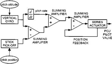
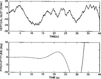
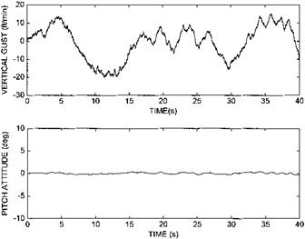
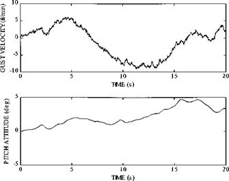
Complete elimination of all long-term ‘nuisance’ modes requires accurate attitude information and so a device sensitive to aircraft attitude, a vertical gyro for example, is used to feed the series actuator (see Fig. 6.23). The power of accurate attitude feedback can be demonstrated by reference to the longitudinal dynamics of the example helicopter when excited by gusts in the form of vertical turbulence. Without attitude stabilization the unstable long-term mode is revealed (see Fig. 6.24). If unity attitude feedback is used this mode is easily stabilized (Fig. 6.25).

As suggested earlier the challenge for the AFCS designer is in obtaining the right

image166

Fig. 6.23 Block diagram of a typical attitude-based stability augmentation system.

image167

Fig. 6.24 Unaugmented gust response of example helicopter (note the у-axis scaling set for comparative purposes).

image168

Fig. 6.25 Gust response of AFCS with unity attitude feedback.

compromise between gust rejection and control response. In its current form the modelled AFCS would completely oppose the pilot since it would treat any pilot induced attitude change as an unwanted deviation from datum. Indeed if the series actuator has sufficient authority it will return the cyclic pitch at the rotor head to the value extant before the pilot made the input. It has already been noted that angular rate feedback can improve the control response by reducing the time constant and enhance gust rejection by generating an error signal before the aircraft attitude has deviated significantly from the datum. Thus a satisfactory situation usually results if pitch or roll attitude is differentiated, or the angular rate is measured directly, and used as an additional error signal provided the attitude feedback signal is inoperative during pilot inputs. The manner in which the attitude signal is disabled will dictate whether the AFCS provides rate command or attitude command.

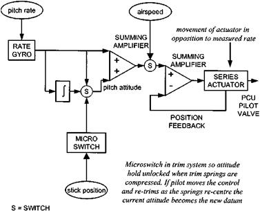
Two basic methods exist: one uses a signal from the stick to switch out the attitude feedback loop whilst the other uses the signal to update the attitude datum. A microswitch placed in the spring-feel unit that only allows attitude feedback when the aircraft is trimmed is an example of the former whereas a device that generates a signal in opposition to the attitude error coming from the gyro (a stick-canceller) is an example of the latter. The microswitch approach would provide the pilot with RCAH provided he is happy to manoeuvre the aircraft without re-trimming and then use a trim-release switch to rapidly re-centre the spring-feel unit. Such a mechanization would also require storage of the datum attitude in some form of memory with the stored value being updated as the cyclic stick is moved against the trim springs.

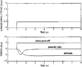
The stick-canceller approach operates by converting stick position into an attitude command that is used to oppose, or cancel, the signal from the attitude sensor. With this type of AFCS, therefore, a step input results in the aircraft capturing a new attitude and thus provides the pilot with the ACAH response type. Another consequence of using a signal from the stick to oppose a steady error signal from the vertical gyro manifests itself during the initial phase on a control input as ‘control quickening’. In

image169

Fig. 6.26 Effect of rate feedback and stick cancellation on actuator drive signals.

order to function correctly the position signal from the pick-off must oppose that coming from the gyro and the series actuator must oppose any angular disturbances sensed by the gyro. The net effect of subtracting the stick signal from the gyro and feeding the result to the series actuator is that the contribution from the stick pick-off becomes additive whereas that from the gyro remains subtractive. Therefore, if the pilot moves the stick rapidly from trim the series actuator will move initially in the same direction. It will only begin to oppose the input when sufficient angular rate and attitude changes have developed (see Fig. 6.26). Note that the series actuator drive signal will be the sum of the three signals presented.

Rate command and short-term attitude hold

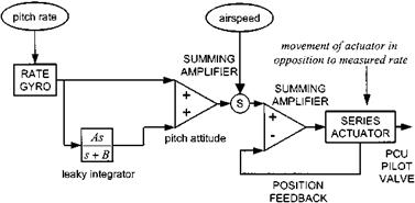
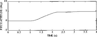
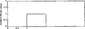
If integrated rate is used then enhanced gust rejection can be expected, as even small angular rates will, over a period of time, generate sizeable attitude errors. However if the pilot moves the control to a new position then, within the authority of the series actuator and all the time an angular rate is present, the AFCS will attempt to drive the attitude back to that occurring before the input was made. One solution to this problem is to arrange for the attitude error signal to ‘leak away’ with time (Fig. 6.19). Thus if the pilot makes a deliberate control input the AFCS will, after a short period of time, take the current attitude as the one about which to hold. Applying an aft pulse (Fig. 6.20), shows a leaky integrator’s effect on the handling qualities. Application of the pulse indicates that the SAS is capable of holding an attitude, selectable by the pilot, for a short period.

image161

Fig. 6.19 Block diagram of a stability augmentation system incorporating a leaky integrator.


1.5 2 2.5

TIME (s)


image163

Fig. 6.20 Pulse response of SAS with leaky integrator.


image162

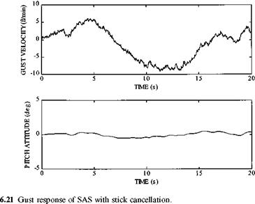
Another solution to unwanted retention of pseudo-attitude hold is simply to switch it off when it is not required. This can be achieved by installing microswitches that disconnect the integrated rate signal when the stick is in motion. When stick movement has ceased the hold can be re-engaged and divergence from the attitude prevailing at that instant will cause movement of the series actuator. Re-engagement of the signal is often dependent on a low rate signal being sensed, 2 degree/second, for example, as well as the lack of any stick movement. The gust response of such a SAS is shown in Fig. 6.21. From this figure it would appear that a satisfactory solution can be achieved as the long-term attitude hold seems reasonable.

It must be remembered, however, that if the attitude signal has been derived from the rate gyro any drift or noise occurring within the rate gyro will compromise the attitude signal thus reducing the effectiveness of the attitude hold. Figure 6.22 shows

image164

image165

Fig. 6.22 Gust response of SAS with noise and drift on rate gyro signal.

the result of including realistic levels of noise into the rate signal causing a deterioration of the attitude hold as expected.

In summary, we can characterize stability augmentation via rate and integrated rate feedback, with the pseudo-attitude signal either allowed to leak or being disabled during manoeuvres, as a system that provides rate command and short-term attitude hold.

Characteristics of typical stability augmentation systems

Before describing the assessment of AFCS equipped aircraft in detail (see Section 7.5) it is worth discussing the characteristics of typical systems that arise from their hardware implementation. In our experience we have found such a discussion to be very useful as the precise design of an AFCS not only affects the conduct of stability and control flight testing but often affects the interpretation of the results obtained from standard test techniques and manoeuvres.

Stability augmentation systems are designed to suppress the longitudinal long-term mode and the LDO. The SAS, in its basic form, consists of a device sensitive to the rate of change of attitude, a rate gyro, which feeds a series actuator placed in the control run. Corrective cyclic pitch inputs are thus made by the SAS in opposition to and proportional to, the rate of change of pitch or roll (see Fig. 6.18). A similar system operates in the yaw channel by feeding corrective inputs to the tail rotor control. An airspeed switch may, however, disable it as the fin tends to provide an increased contribution to yaw damping at high airspeed.

As discussed briefly in a previous chapter increased rate damping (angular rate feedback) can be used by the control law designer to enhance the control response characteristics of the helicopter by making the time to steady rate shorter (improved predictability) at the expense of a reduced output. Thus there is a strong argument for retaining the rate feedback path whilst the pilot is manoeuvring the helicopter.

image160

Fig. 6.18 Block diagram of a typical rate-based stability augmentation system.

Unfortunately it may be difficult to find an optimal gain that provides adequate gust rejection as well as appropriate control response shaping.

In order to improve the handling qualities of the helicopter, beyond the application of rate feedback, it is usually necessary to apply corrective cyclic inputs in response to attitude changes (integral feedback). This can be achieved either by integrating the signal from the rate gyro (pseudo-attitude) or by direct measurement of the aircraft’s true attitude. In each case the signal is fed back to the series actuator to provide a command that opposes deviations from some attitude datum. Note that integrated rate is not incorporated into the yaw channel, as it does not relate well to aircraft heading. The key issue arising from this control law improvement concerns how the attitude signal is disabled during manoeuvres and what response type results: Rate Command/Attitude Hold (RCAH) or Attitude Command/Attitude Hold (ACAH).

Quadruplex

Increasing the level of redundancy to four separate lanes of AFCS would be necessary if voting logic was used and continued augmentation after two failures was required. The system reliability may be less than expected, however, due to mechanical complex­ity involved in this level of redundancy particularly as rotorcraft do not have multiple means of generating control forces and moments about a given axis. The advent of digital computation and self-monitoring, as mentioned above, have enabled a triplex system to perform at the level of fault tolerance formerly possible only with a quadruplex system. It is probable, therefore, that in the future, a quadruplex, digital AFCS with self-monitoring would only be fitted on an aircraft with catastrophic failure modes. Such a system, based on a component MTBF of 1000 hours, would have a theoretical probability of total failure of 7.1 x 10_n per hour or an MTBF of over 1 200 000 000 hours.

6.5.4.4 Signal consolidation

All the systems described above have consisted of separated lanes of AFCS with consolidation only at the main servo jack. Alternative architectures arrange for all the sensor signals to go to all of the computers and for all of the computers to drive all of the actuators. This serves to improve the availability of the system because a lane containing a failed component can continue to operate using signals from the surviving components in the other lane(s). Although theoretically the reliability is not changed, actually there will be an improvement because common failures or simultaneous dissimilar failures in the different lanes will be required before the AFCS integrity is in question.

6.5.4.6 Failure modes, effects and criticality analysis

The systems described above have been necessarily simplistic and have assumed independent sensor packages and electrical/hydraulic supplies to each lane. Actual systems are generally more complicated with the precise system architecture varying with aircraft type or AFCS manufacturer. Typically a triplex, or quadruplex, system may still offer augmentation following a range of failures but at a degraded level and within a reduced flight envelope. In addition, optional sensors may be used to provide a synthetic signal following failure of the primary sensor. For example, a rate gyro signal may be integrated and used to replace the signal from a failed vertical reference system (VRS).

It should be clear that to assess an AFCS requires a detailed knowledge of the system architecture and its intended modes of operation, including operation following failures. An evaluation called a Failure Modes, Effects and Criticality Analysis (FMECA) is usually conducted in order to determine the likely effects of all conceivable failures to ensure the validity of any degraded modes assessment conducted as part of the flight test programme. Due to the limited time available only the more probable failure cases will be subject to an in-flight assessment. So, for example, although there may be a variety of failures that could lead to the loss of a primary sensor, such as a vertical gyro, or the loss of a lane in a multiplexed system, flight testing would simply involve assessing the permissible envelope with a single lane disengaged or with the feed from the gyro disabled. It is, however, worth remembering the number of occasions that the FMECA has proved, through bitter flight experience, to be incomplete. For example, supposedly dissimilar components in individual lanes that are all susceptible to the same common mode failure due to a similarity in design.

Reliability and availability

When an aircraft is evaluated for a particular role the reliability of the complete vehicle will be almost as important as the handling qualities that it possesses. Thus the vehicle specification will often include some statement of the minimum acceptable reliability. When a helicopter is fitted with an AFCS, on which it depends for normal operation, the reliability of this system has increased importance. It is usual for the system availability to be specified when serious degradation of the handling qualities results from total AFCS failure. Thus some minimum number of major failures is specified before any degradation in AFCS performance is allowed.

The reliability of an AFCS is usually defined as the probability of total system failure, but can also be expressed as a mean time between failure (MTBF). In the case of an ACT helicopter such a failure would be catastrophic, most likely resulting in the loss of the aircraft, and so the specified reliability of the overall flight control system would be very high. Typical figures are 10 ~9 per flight hour for civil applications and 10 ~7 for military systems. Associated with reliability requirements is the availability of a system. This is defined as the requirement that it should continue to operate after a specified number of major failures. For example, a system may be specified such that it shall function correctly after one or two failures. Clearly, this implies duplication, or redundancy, in the system. Redundancy is often required to ensure that the AFCS meets the necessary reliability since individual component reliability cannot be guaranteed for the extreme MTBFs specified.

The degree of multiplexing, or redundancy, incorporated into an AFCS will depend on the handling qualities of the unaugmented aircraft and whether successful completion of the mission is dependent on AFCS integrity. Degrees of multiplexing can be ranked in order of increasing fault tolerance. To gain some idea of the theoretical improvement in reliability, an individual component MTBF of 1000 hours has been assumed in the following examples.

6.5.4.1 Simplex

A simplex system has no built-in fault tolerance and will cease to function following a single failure. Thus a simplex AFCS would only be acceptable in a helicopter with acceptable unaugmented handling qualities and when the majority of the mission could be completed satisfactorily with the ‘raw’ aircraft. A simplex system may be reduced to the main components (sensors/computer/actuator), all of which are required for satisfactory operation. The probability of failure of the example system would be, typically, 3 x 10 ~3 per hour, giving a MTBF of approximately 330 hours.

6.5.4.2 Duplex

The duplex system consists of two completely separate AFCS systems, from sensors through to actuators although the actuation will be combined at the pilot valve of the main servo jack. Without any form of system monitoring it is impossible to arrange for automatic deselection of a malfunctioning lane and therefore the system would have a probability of first failure similar to the simplex AFCS. In fact it might be worse since there are twice as many components in this system. The advantage it has over a simplex system is that a runaway in one lane will be sensed and countered by the other, assuming that a simultaneous failure has not occurred, therefore the ensuing departure from controlled flight will be more benign. Unfortunately fault diagnosis will be more difficult since the pilot has no way of determining which lane has failed and which operated correctly to counter the disturbance. Therefore the handling qualities of the raw aircraft must still be acceptable to ensure flight safety during the fault diagnosis and deselection process. More modern duplex systems feature digital computation that enables self-monitoring at the expense of increased computation time. This is often achieved by engineering a pseudo third lane that monitors sensor information and determines the appropriate actuator response. Using this approach it is possible to indicate a failed lane or to arrange for automatic deselection, in which case the probability of system failure resulting in visibility of the raw handling qualities reduces to 9 x 10 6 per hour giving an MTBF of over 110000 hours as two failures are now required before augmentation is lost.

6.5.4.3 Triplex

Three separate lanes are necessary in aircraft where the handling qualities dictate the need for stability augmentation following two failures or where their impact on manual fault diagnosis and manual deselection of a failed lane are unacceptable. As noted above this latter requirement can now be satisfied using a self-monitored duplex (or pseudo triplex) system. In all cases however automatic monitoring and deselection of a single failed lane requires the presence of three signals so that the two good lanes can ‘vote’ out the bad one. Such a system can survive a single failure with no change in handling qualities although it provides no protection against a common mode failure that causes two signals to go bad at the same time. Following a first failure, however, in the event of a disparity between the two surviving channels the voting logic will fail and the aircraft will suffer a total loss of augmentation just like that caused by a single failure in the duplex system. It is at this point that the greater the availability provided by triplex systems becomes evident in that the crew can regain augmentation after the second failure provided the surviving lane can be correctly identified. Once again, through the use of self-monitoring, modern digital systems can improve the situation by providing automatic deselection following a second failure, thereby reducing the probability of total failure to 2.7 x 10 ~7 per hour, a MTBF of 37000000 hours.

Transparency and override facilities

Automatic flight control systems that feature outer loop modes need to be carefully designed so that the pilot is able to make control demands without having to overcome an opposing input from the AFCS. Ideally movement of the controls in the cockpit should cause the relevant hold to be disabled, either permanently or temporarily, depending on the circumstances. If well designed the functioning of the basic holds (attitude, heading and height) can be transparent to the pilot.

Of particular importance is the blend between heading hold and turn co-ordination or more simply heading hold on and off. In forward flight the initiation of a turning manoeuvre is signalled by the application of lateral cyclic and this is used by the AFCS designer to unlock the heading hold and use the yaw series actuator (and parallel if fitted) to help generate the necessary yaw rate for a balanced turn. Thus a natural blend is achieved and, as far as the pilot is concerned, the helicopter changes transparently from maintaining a heading in straight and level flight to performing a Rate 1 turn for example. In the low speed regime the situation is different since during a lateral transition or side-step the pilot will expect the heading to be maintained. Therefore some form of airspeed switch is required to prevent heading hold unlock at low forward speed.

Rotorcraft AFCS without automatic turn co-ordination or an airspeed switch present the designer with more of a challenge in that he can no longer use lateral cyclic to unlock the heading hold. Instead a sensor is placed in the yaw control run so that if the pilot attempts to initiate a yaw rate by application of pedal the heading hold is disengaged. Unless this is carefully engineered the AFCS may suffer a lack of transparency that in extremis makes the helicopter harder to turn with the AFCS on than with it off.

Some AFCS provide the pilot with a range of programmed manoeuvres such as automatic transitions, auto-ILS and waypoint steerage, that often require large move­ments of the controls within the cockpit under the action of a parallel actuator. It is usual, therefore, for the pilot to be provided with an override or cut-out button so that in the event of a runaway, some other failure or a change of mind, he can disengage part or all of the mode either permanently or temporarily as the situation dictates. So for example the Westland Sea King ASW helicopter is provided with both cyclic and collective cut-outs to disengage parts of the automatic transition programme. Similarly helicopters fitted with height holds have cut-outs, usually located on the collective, to disengage the hold and some have a manoeuvre button to allow temporary disengagement of the hold as a new datum altitude is set.

Output devices

Clearly the AFCS needs to move the controls of the helicopter in order to achieve the aims of the control law design, therefore, some form of actuator connected to the controls must be used for this purpose. The actuator may be either electro-mechanical or electro-hydraulic and it may operate in series with, or parallel to, the control run.

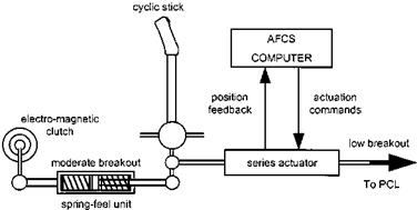
Series actuators can be considered as an extendable portion of the control run whose length is under the control of the AFCS (see Fig. 6.16). Usually the breakout force at the cockpit control is greater than that at the pilot valve of the main control servo and so, as the AFCS actuates the pitch change linkages, no movement of the primary inceptors occurs. In this way the AFCS designer can augment the stability of the host aircraft without causing unwanted movement of the cockpit controls. Transi­ents on engagement/disengagement of the system are possible, as the actuator must re-centre and become a rigid link when the AFCS is inoperative so that no lost motion is introduced. Most control laws involve some enhancement of the damping of the host aircraft by responding to undemanded angular rates. Consequently the series actuators need to be rapid acting and therefore must have limited authority so that the aircraft response to an active failure, such as a hardover or runaway, is not catastrophic and that the available control range following such a failure remains adequate. About +10% is typical, which means that series actuation alone is unlikely to have the control authority to be suitable for all autopilot functions, especially those

image158

Fig. 6.16 Series actuation.

involving large changes in flight path such as automatic transitions and turn co­ordination.

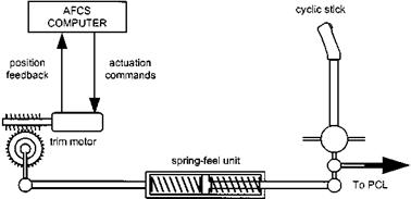
The parallel actuator is coupled to the control run in such a way that the cockpit control is moved as the actuator operates (see Fig. 6.17). Consequently the actuator has full authority and so the actuation rate must be a compromise between the requirement to move the control run rapidly, so that the associated series actuator is prevented from saturating, and the active failure characteristics. Unlike with series actuation there is no AFCS reason for breakout at the cockpit control. The actuator is often coupled to the control run by means of an electro-magnetic clutch and, therefore, disengagement can be made at any time without disturbance to the flight path. It is common practice to provide parallel actuation in the collective and yaw channels because outer loop modes, such as heading steer, often suffer from series actuator saturation. Trim motors acting on the cyclic stick can also serve as parallel actuators in providing a follow-up trim mode that uses the spring-feel unit to move the complete control run, thus keeping the series actuator nulled and able to exert approximately equal authority in both directions at all times. Parallel actuators are usually electro-mechanical as high operating speeds are neither required nor desired.

image159

Fig. 6.17 Parallel actuation.

Computers

The computation performed by the data processing part of an AFCS may be simple or complex depending on the type of system and degree of augmentation provided. Many older systems based around an analogue computer are still in operation, some of which provide limited outer loop modes such as height hold and automatic transitions. More modern and sophisticated systems such as fully capable autopilots suited for single pilot IFR operations and FBW installations require the flexibility and ease of control law implementation offered by digital computers. Some of the more common functions of the computer are:

• Amplification. To increase the signal strength from the sensor to a level high enough to be effective at the output stage.

• Integration. To derive synthetic attitude information from a rate gyro signal or translation rate from acceleration.

• Differentiation. To derive synthetic rate information from a vertical gyro signal.

• Summation. To generate an error signal by comparison of the pilot demand with the output from the appropriate sensor or to blend angular rate and attitude feedback signals.

• Limiting. To contain the effect of certain parameter changes within predetermined limits or to contain the effect of sub-system failures.

• Shaping. To adapt the control strategy and handling qualities to suit the particular mission phase.

• Programming. To produce a precise manoeuvre, such as an automatic transition, in the absence of positional data.

• Blending. The use of a particular parameter, such as airspeed, to modify the gain or functioning of an AFCS feature.

Sensors

Sensors are required in order that the flight control computer is aware of the state of the aircraft and position of the primary flight controls. The simpler stability augmenta­tion systems require information from rate gyros whilst attitude stabilization requires a signal from a vertical gyro, or from integrating the rate signal. A gyrocompass will be used for heading hold. More complex autopilot systems will require more sensors, many of which may also be used to provide the pilot with flight information. Sensors include:

• a pitot/static system for speed and height holds (for safety reasons this system is usually separate from that which feeds the first pilot’s instruments);

• the navigation suite for waypoint steering;

• lateral accelerometers for turn co-ordination;

• ILS receivers for coupled approaches;

• Doppler or GPS receivers for automatic hover position hold.

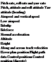
A fuller list of the sensors currently used in helicopter automatic flight control systems is given in Table 6.3.

Table 6.3 Automatic flight control system – parameters and sensing systems.

Parameter Sensors

Подпись: Pitch rate, roll rate and yaw rate Pitch, attitude and roll attitude Yaw attitude (heading) Airspeed and vertical speed Low airspeed Sideslip Sideforce Normal acceleration Altitude Height Along and across track velocities Hover plan position Flight path data Control positions Control position (discrete) Rate gyroscope or differentiated attitude

Vertical gyroscope or integrated rate

Gyrocompass

Pitot-static system

HADS or other low airspeed sensor

Yaw vane or differential static pressure

Lateral accelerometer

Accelerometer

Static system or separate aneroid Radar altimeter Doppler radar, IN or GPS Doppler radar, GPS or cable angle ILS, VOR, DME, GPS or IN Position pick-off or force sensor Microswitch

System components

The constituent parts of most AFCS can be grouped into four classes of components, namely:

• Inceptors. Devices that the pilot uses to communicate with the AFCS and to make control inputs.

• Sensors. These are used to measure the relevant reference parameter and transmit the necessary information to the computer.

• Computers. These convert the sensor information and pilot demands into signals to drive the output devices.

• Output devices. These convert the computer signals into a form that will result in the required helicopter movement. The output may be direct, in the form of actuators which move the pitch change links, independently or via the cockpit controls, or indirect in the form of a cockpit display, a ‘flight director’, which will direct the pilot to make the necessary control movements himself.

6.5.3.1 Inceptors

Inceptors refer to the devices used by the pilot to make inputs to the FCS. The simplest and most conventional are the traditional cyclic stick, collective lever and pedals which the pilot uses to command changes to the aircraft attitude and power setting. The selection and adjustment of holds, such as heading, height or airspeed are often made by means of switches and knobs, either located on the primary inceptors or close to the associated flight instrument. It is worth noting that the use of electronic flight information systems (EFIS) have allowed some consolidation of these controls.

The absence of a mechanical link between the cockpit control and the rotor head, which has been made possible with the advent of FBW, has given the cockpit designer greater freedom. Although mechanically coupled side-stick arrangements have be used in some non-FBW attack helicopters, the mechanical tailoring has been necessarily limited. Consequently there has been a great deal of research into the best style and location for active versions of these inceptors. It has now been generally agreed that a small stick, located centrally or to the right, and some form of collective lever, or second side-stick controller, will be used. Such an installation can improve pilot comfort by allowing the optimization of inceptor position, FCMC and adjustment, and improve cockpit layout by allowing more appropriate positioning of displays, instruments and switches, due to the smaller envelope occupied by the side-stick controllers (SSCs) and the possible removal of the yaw pedals. At present little agreement exists concerning the controls that will be assigned to these novel inceptors. Three configurations have been evaluated, these are:

• A two-axis SSC located to the right (2R), a collective (1C) and pedals (1P) or (2R + 1C + 1P).

• A three-axis SSC located to the right and a collective or (3R + 1C).

• A four-axis SSC located to the right or (4R).

Research conducted in Europe as part of the EuroACT programme concentrated on a passive (3R + 1C) system and an active (2R + 1C + 1P) system. The passive system provided the pilot with a fixed set of spring feel characteristics, whereas the active system allow the tailoring of the feel characteristic to suit the current handling task. The more conventional configuration was selected for the active system in order to simplify the basic stick design so that incorporation of actively variable FCMC was possible. Recent research has highlighted the following:

(1) SSC design characteristics, such as grip shape, arm support and the length of the pivot arm, can have a profound effect on the handling qualities due to anatomically induced cross-coupling.

(2) Isometric (or rigid) and low compliance (or movement) SSCs are undesirable because of their lack of control magnitude and control position cues.

(3) Four-axis SSCs have the advantage of freeing a hand for other tasks. But significant handling deficiencies are experienced due to anatomical coupling. It is very difficult for the pilot to make single axis inputs, particularly in heave, thereby complicating certain piloting tasks, such as slope landings. Dynamic multi-axis tasks such as quickstops are also difficult to perform with this type of inceptor.

(4) Surprisingly, three-axis SSCs with twist for yaw control are well accepted by pilots provided it is coupled with an accurate heading hold incorporating an integral trim that obviates the need to hold-off a force during out-of-wind hovering for example.

Control of autopilot modes is generally by means of appropriate knobs and switches. These may be duplicated so that a range of the more important functions can be selected or deselected from the primary flying inceptors. The selection and control of certain modes, such as airspeed hold and vertical speed hold may be via controls incorporated into the appropriate flight instruments. Alternatively, a repeater screen may be fitted that displays the current hold setting. The displayed data changes depending on the hold selected and the datum is adjusted by means of switches on the primary flight inceptors.