Category Introduction to Structural Dynamics and Aeroelasticity

The p-k Method

The к method is still popular in industry largely because of its speed. Although it provides significant advantages to the practicing aeroelastician, it is a mathematically
improper formulation. The impropriety of imposing simple harmonic motion with the introduction of artificial damping precipitated many heated discussions through­out the industry. It has been argued that for conditions other than the g = 0 case, the frequency and damping characteristics do not correctly represent the system behavior. As a result, design changes that are made based on these characteristics can lead to expensive and potentially dangerous results.

In 1971, Hassig presented definitive numerical results that clearly indicated that the к method of flutter analysis can exhibit an improper coupling among the modes of motion. His presentation utilized a simple form of unsteady aerodynamics in a к method analysis, and then he compared the results with those from a p method analysis. Recall that the p method presented in Section 5.1 is already established as the most accurate solution. Here, we show how both к and p-к methods relate to it.

In the p method, the general solution to the homogeneous modal equations of motion given by Eqs. (5.7) can be written in terms of a dimensionless eigenvalue parameter p = bv/U, where

fІ (t) = £ i exp(vt) (5.70)

Подпись: 2 b2 2 p [M] + w['M][«2'] - pTO[A(p)] Подпись: {£} = 0 Подпись: (5.71)

Substitution of this expression into Eqs. (5.7) yields n + N linear, homogeneous equations for the n £is and the N Xs given as Eqs. (5.11). After eliminating the Xs using the second of Eqs. (5.11), we may rewrite the first of those equations symbolically as

where [‘M] and [юг-] are diagonal matrices with elements Ml, M2, …,Mn and «2, «2, respectively; n is the number of modes; and the unsteady aerody­

namics operator matrix [A( p)] can be expressed in terms of the other matrices in Eqs. (5.11)—namely, in terms of [a], [b], [c], [d], [A], and [E]. The complex matrix [A(p)] is made up of so-called aerodynamic-influence coefficients (AlCs). These coefficients are functions of p and possibly of the Mach number, depending on the sophistication of the aerodynamic theory.

If the Xs are actually eliminated, then the problem, in general, cannot be ex­pressed as a standard eigenvalue problem. This is not a serious obstacle, however, because we can always solve Eqs. (5.11) as a standard eigenvalue problem. The purpose here for eliminating the Xs is only to provide a convenient segue into the к and p-к methods and show explicitly the differences among the three methods. The important thing to note is not the procedure used to obtain Eq. (5.71); rather, it is the form of this equation that is most important at this stage. The coefficients A( p) frequently can be determined or identified in other ways. This equation is the basis for the p method in one of its usual forms. For a nontrivial solution of the generalized coordinate amplitudes, the determinant of the coefficient matrix in

The p-k Method

At selected values of reduced frequency and altitude, Eq. (5.75) can be solved for the complex roots of b2/ U2, denoted by Xr + iXi. These roots may be interpreted as

Xy + іXi = (1 + ig) (5.76)

where g is the structural damping required to sustain simple harmonic motion. This structural-damping parameter can be related to the rate of decay parameter of the p method as

g = 2y (5.77)

This is a good approximation for small damping as in the case of flight vehicles. The к method is posed easily as a standard eigenvalue problem, which is clear from Eq. (5.75). This alone gives it a significant advantage over the classical flutter – determinant method outlined in Section 5.3.

Another important aspect in making any correlation between the p and к meth­ods is the matter of adequate inclusion of compressibility effects in the unsteady – aerodynamic terms. In the p method, the flutter determinant is solved for selected combinations of speed and altitude. Consequently, the appropriate Mach number can be used for the aerodynamic terms at the outset of the computation. In contrast, the к method preselects combinations of reduced frequency and altitude. As a result of then computing the airspeed as an unknown, Xr, the Mach number cannot be accurately specified a priori. The result is that an iterative process similar to the one described in Section 5.3 must be conducted to ensure that compressibility effects are adequately incorporated in the к method.

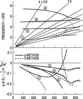
Figure 5.6. Comparison between p and k methods of flutter analysis for a twin – jet transport airplane (from Hassig [1971] Fig. 1, used by permission)

Подпись: V-KEASПодпись: 0.7 0.6 0.5 0.4 0.3 The p-k MethodHassig applied the p and k methods of flutter analysis to a realistic aircraft configuration. By incorporating the same unsteady-aerodynamic representation in each analysis, he was able to make a valid comparison of the results. His observations are typified by Fig. 5.6 (which is his Fig. 1). Note from this figure that not only is the modal coupling wrongly predicted by the k method but also, more important, the wrong mode is predicted to become unstable. The only consistently valid result between the two analyses is that of the flutter speed for which g = у = 0. Despite the inconsistent modal coupling exhibited by the k method, it permits the use of simple harmonic modeling of the unsteady aerodynamic terms. As previously mentioned, the accuracy of simple harmonic airload predictions exceeds the accuracy of airload predictions for transient motions. It is for this reason that a compromise between the two models was suggested.

Подпись: 2 b2 2 P2[M] + Jj2 [M][a>] - Px[A(ik)] Подпись: 0 Подпись: (5.78)

The p-k method is such a compromise. It is based on conducting a p-method type of analysis with the restriction that the unsteady-aerodynamics matrix is for simple harmonic motion. Using an arbitrary value of k in computing [A(ik)], we find the flutter determinant to be

Given a set of initial guesses for k—say, ko = Ьщ /U for the ith root—this equation can be solved for p. Moreover, it can be posed as a standard eigenvalue problem for p because p appears only in a simple way. The typical result is a set of complex

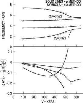
Figure 5.7. Comparison between p and p-k methods of flutter analysis for a twin-jet trans­port airplane (from Hassig [1971] Fig. 2, used by permission)

The p-k Methodconjugate pairs of roots and possibly some real roots. Selecting one of the complex roots and denoting the initial solution as

k = |ЭД| Y1 = ^p (5.79)

we can compute [ A(ik{)]. Using this new matrix in Eq. (5.78) leads to another set of ps, so that

k2 = p(p)! Y2 = (5.80)

k2

Continual updating of the aerodynamic matrix in this way provides an iterative scheme that is convergent for each of the roots, negative Y being a measure of the modal damping. The earliest presentation of this technique was offered by Irwin and Guyett in 1965. For low-order problems, it is straightforward to use a root-finding procedure in which the determinant obtained from setting k = |S(p) | is required to vanish.

Hassig applied the p-k method to the configuration in Fig. 5.6. As illustrated by Fig. 5.7 (which is his Fig. 2), the p-k method appears to yield approximately the same result as the p method. This, of course, simply validates the convergence of the scheme. Its greatest advantage is that it can utilize airloads that have been formulated for simple harmonic motion. Another comparison offered by Hassig was between the widely used k method and the p-k method for a horizontal stabilizer/elevator configuration. This example of a strongly coupled system provided the results given

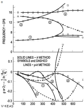
Figure 5.8. Comparison between p-к and к methods of flutter analysis for a horizontal stabilizer with elevator (from Hassig [1971] Fig. 3, used by permission)

Подпись: □ V-KEAS in Fig. 5.8 (which is his Fig. 3). Here again, as in the к versus p comparison in Fig. 5.6, widely differing conclusions can be drawn regarding the modal coupling. In addition to the easily interpreted frequency and damping plots versus airspeed for strongly coupled systems, a second advantage is offered by the p-к method regarding computational effort. The к method requires numerous computer runs at constant density to ensure matching of the Mach number with airspeed and altitude. The p-к method does not have this requirement.

The accuracy of the p-к method depends on the level of damping in any particular mode. It is left as an exercise for readers (see Problem 14) to show that the p-к method damping is only a good approximation for the damping in lightly damped modes. Fortunately, these are the modes about which we care the most. Methods presently used in industry are described by Goodman (2001). Currently, most flutter analyses in the aircraft industry are performed using к and/or p-к methods. Although the к method remains popular because of its speed, when accuracy is important and the p method is not feasible, industry users seem to favor the p-к method, especially those who run the NASTRANTM aeroelasticity package.

The k Method

Subsequent to Theodorsen’s analysis of the flutter problem, numerous schemes were devised to extract the roots of the “flutter determinant” and thereby identify the stability boundary. Scanlan and Rosenbaum (1951) presented a brief overview of these techniques as they were offered during the 1940s. It was fairly common to include in the flutter analysis a parameter that simulated the effect of structural damping. Observations at that time indicated that the energy removed per cycle during a simple harmonic oscillation was nearly proportional to the square of the amplitude but independent of the frequency. This behavior can be characterized by a damping force that is proportional to the displacement but in phase with the velocity.

To incorporate this form of structural damping into the analysis of Section 5.3.2, Eqs. (5.54) can be written as

Подпись:Подпись: (5.65)m(h + bxe0) + khh = – L + Dh IP 9 + mbxg h + kgg = M + Dg where the dissipative structural damping terms are

Dh = Dh exp(i at)

= – ighma>2hH exp(i at)

Dg = Dg exp(i at)

= – igg Ipagjg exp(i at)

The k Method Подпись: (5.66)

Proceeding as before, Eqs. (5.62) become

The damping coefficients gh and gg have representative values from 0.01 to 0.05 depending on the structural configuration. Most early analysts who incorporated this type of structural damping model into their flutter analyses specified the coefficient values a priori with the intention of improving the accuracy of their results.

Scanlan and Rosenbaum (1948) suggested that the damping coefficients be treated as unknown together with m. In this instance, the subscripts on g can be removed. Writing a = mh/me as before, and introducing

Подпись: we obtain the flutter determinant as p (1 - a2Z) + lh pxe + mh Подпись: pxe + le pr2 (1 - Z) + me Подпись: = 0 Подпись: (5.68)

Z = © 2(1 + ig) (5.67)

Подпись: ZL,2 Подпись: me «1,2 Подпись: 2 (1 + ig1,2) Подпись: (5.69)

which is a quadratic equation in Z. The two unknowns of this quadratic equation are complex, denoted by

The computational strategy for solving Eq. (5.68) proceeds in a manner similar to the one outlined for Eq. (5.63). The primary difference is that the numerical results consist of two pairs of real numbers, (m1, g1) and (m2, g2), which can be plotted versus airspeed U or a suitably normalized value such as U/(bme) or “reduced velocity” 1/к.

Plots of the damping coefficients g1 and g2 versus airspeed can indicate the margin of stability at conditions near the flutter boundary, where g1 or g2 is equal to zero. These plots proved to be of such significance that the technique of incorporating the unknown structural damping was initially called the “U-g method.” Recalling that the methodology presumes simple harmonic motion throughout, the numerical values of g1 and g2 that are obtained for each к can be interpreted only as the required damping coefficients (of the specified form) to achieve simple harmonic motion at frequencies m1 and m2, respectively. The damping as modeled does not really exist; it was introduced as an artifice to produce the desired motion—truly an artificial structural damping.

The plots of frequency versus airspeed in conjunction with the damping plots can, in many cases, provide an indication of the physical mechanism that leads to the instability. The values of frequency along the U = 0 axis correspond to the coupled modes of the original structural dynamic system. As the airspeed increases, the individual behavior or interaction of these roots can indicate the transfer of energy from one mode to another. Such observations could suggest a way to delay the onset of the instability. To confirm identification of the modes of motion for any specified reduced frequency, it is only necessary to substitute the corresponding eigenvalues, mi and gi, into the homogeneous equations of motion to compute the associated eigenvector (h/b, Є). Because this is a complex number, it can provide the relative magnitude and phase of the original deflections h and e.

Engineering Solutions for Flutter

It was noted in the preceding section that the presumption of simple harmonic motion in classical flutter analysis has both advantages and disadvantages. The prime argument for specification of simple harmonic time dependency is, of course, its correspondence to the stability boundary. Identification of the flight conditions along this boundary requires the execution of a tedious, iterative process such as the one outlined in Section 5.3. This type of solution can be attributed to Theodorsen (1934), who presented the first comprehensive flutter analysis with his development of the unsteady airloads on a two-dimensional wing in incompressible potential flow.

Although unsteady-aerodynamics analyses for simple harmonic motion are not simple to formulate and execute, they are far more tractable than those for oscillatory motions with varying amplitude. Since the work of Theodorsen, numerous unsteady – aerodynamic formulations have been developed for simple harmonic motion of lifting surfaces. These techniques have proven to be adequate for compressible flows in both the subsonic and supersonic regimes. They also have been developed for three-dimensional surfaces and, in some cases, with surface-to-surface interaction. This availability of relatively accurate unsteady-aerodynamic theories for simple harmonic motion was the stimulus for further development of flutter analyses beyond that of the classical flutter analysis described in Section 5.3.

There are two other important considerations of practicing engineers. The first is to obtain an understanding of the margin of stability at flight conditions in the vicinity of the flutter boundary. The second—and possibly the more important—is to obtain an understanding of the physical mechanism that causes the instability. With this information, engineers can propose design variations that may alleviate or even eliminate the instability. When a suitable unsteady-aerodynamic theory is available, the p method can address these considerations. In this section, we examine alternative ways that engineers have addressed these problems when unsteady – aerodynamic theories that assume simple harmonic motion must be used.

Two-Degree-of-Freedom Flutter

The analysis of multi-degree-of-freedom systems for determination of the flutter boundary can be demonstrated adequately by the simple two-degree-of-freedom configuration in Fig. 5.2. The equations of motion, already derived as Eqs. (5.26), are repeated here as follows:

Подпись: (5.54)m(h + bxe’d) + khh = — L Ip6 + mbxe h + крв = M

Подпись: M = Mi + b 4 Подпись: L Подпись: (5.55)

where, as before

The next step in classical flutter analysis is to presume that the motion is simple harmonic as represented by

Подпись: (5.56)Подпись: (5.57)h = h exp(i at) в = в exp(i at)

The corresponding lift and moment can be written as

L = L exp(i at)

M = M exp(i at)

—ш[7]тЬхв h — a2 Ip в + IP а2в = M

Two-Degree-of-Freedom Flutter Two-Degree-of-Freedom Flutter

Substituting these time-dependent functions into the equations of motion, we obtain a pair of algebraic equations for the amplitudes of h and в in the form

Подпись: M = np^b^a2mh (k, MTO) b + me (k, MTO) в

Two-Degree-of-Freedom Flutter Two-Degree-of-Freedom Flutter Подпись: (5.60)

Substituting these lift and moment amplitudes into Eqs. (5.58) and then rearranging, we obtain a pair of homogeneous, linear, algebraic equations for h and в, given by

Two-Degree-of-Freedom Flutter Подпись: (mass ratio) Подпись: (5.61)

The coefficients in these equations that involve the inertia terms are symbolically simplified by defining the dimensionless parameters used previously; namely

r — A/ m_2 (mass radius of gyration about P)

(pxe + mh) b + pr1 [8]

Подпись: p Подпись: 1 - Є)2 Two-Degree-of-Freedom Flutter Подпись: (5.62)

Using these parameters allows us to rewrite the previous two homogeneous equa­tions in a simpler way:

Подпись: p Подпись: 1 - *2 (юв)2 pxe + mh Подпись: + £h Подпись: pr Two-Degree-of-Freedom Flutter Подпись: 0 Подпись: (5.63)

The third step in the flutter analysis is to solve these algebraic equations for the flight condition(s) for which the presumed simple harmonic motion is valid. This result corresponds to the flutter boundary. If it is presumed that the configuration parameters m, e, a, IP, rnh, юв, and b are known, then the unknown quantities h, в, ю, pTO, Mm, and к describe the motion and flight condition. Because Eqs. (5.62) are linear and homogeneous in h/b and в, the determinant of their coefficients must be zero for a nontrivial solution for the motion to exist. This condition can be written as

The determinant in this relationship is called the “flutter determinant.” Note that the parameter a — a>h /юв was introduced so that a common term that is explicit in ю is available—namely, юв/ю. Thus, expansion of the determinant yields a quadratic polynomial in the unknown X — (юв/ю)2.

To complete the solution for the flight condition at the flutter boundary, it must be recognized that four unknowns remain: юв/ю, p — m/(npTOb2), MTO, and к — Ью/U. The one equation available for their solution is the second-degree poly­nomial characteristic equation from setting the determinant equal to zero. However, because the aerodynamic coefficients are complex quantities, this complex equation represents two real equations, wherein both the real and imaginary parts must be identically zero for a solution to be obtained. This means that two of the four un­knowns must be specified. A procedure to solve for and map the flutter boundary is outlined as follows:

3. Recalling that setting the flutter determinant equal to zero yields a quadratic equation in X, use a root-finding application[9] to find the value of k at which the imaginary part of one of the two roots for X vanishes, which is kF. This can be carried out easily with computerized symbolic manipulation software such as Mathematica™ or Maple™

4. Set mg/mF = т/X(kF) using the root for which X(kF) is real.

5. Determine UF = bmF/kF and MmF = UF/cTO.

6. Repeat steps 3-5 with the value of MCXJF obtained in step 5 until converged values are obtained for MCXJF, kF, and UF for flutter at a given p.

7. Repeat the entire procedure for various values of p (i. e., an indication of the altitude for a given aircraft) to determine the flutter boundary in terms of, say, altitude versus M(XlF, kF, and UF.

One-Degree-of-Freedom Flutter

To illustrate the application of classical flutter analysis, a simple configuration is treated first. This example is a one-degree-of-freedom aeroelastic system consisting of a rigid two-dimensional wing that is permitted to rotate in pitch about a specified

One-Degree-of-Freedom Flutter

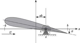
Figure 5.5. Schematic of the airfoil of a two-dimensional wing that is spring-restrained in pitch


reference point. This is a special case of the typical-section configuration shown in Fig. 5.2 for which the plunge degree of freedom is equal to zero, as depicted in Fig. 5.5. The system equations of motion reduce to one equation that can be written as


One-Degree-of-Freedom Flutter

M = M exp(i at)


(5.43)


where


One-Degree-of-Freedom Flutter

(5.46)


ав = .


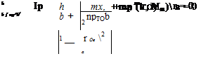
and rearranging the algebraic relationship, we obtain the final equation to be solved for the flight condition at the flutter boundary as


IP


+ me (к, MTO) = 0


(5.47)


1


npTOb4


To solve this equation, it is presumed that the configuration parameters Ip, , and b

are known. The unknown parameters that describe the motion and flight condition are rn, pTO, k, and Mro. These four unknowns must be determined from the single algebraic equation, Eq. (5.47). Because the aerodynamic coefficient, mp(k, Mro), is complex, it can be written as

me (k, Mro) = Щ[тв (k, M«>)] + i»[m0 (k, Mro)] (5.48)

Подпись: IP nprob4 Подпись: 1 - Подпись: + Щщ (k, 0)] + iS[m0 (k, 0)] = 0 Подпись: (5.49)
One-Degree-of-Freedom Flutter

As a consequence, both the real and imaginary parts of the algebraic relationship must be zero, thus providing two real equations to determine the four unknowns. Therefore, two of the unknown parameters should be specified. A fixed altitude is chosen that specifies the freestream atmospheric density, pro. The second parameter to be fixed is the Mach number, which can be given a temporary value of zero. This, of course, implies that the flow is incompressible and the aerodynamic-moment coefficient is then only a function of the reduced frequency. The governing algebraic equation now can be written as

Equating the imaginary part of the left-hand side to zero gives a relationship that can be solved for the reduced frequency, kF, at the flutter boundary; that is

Подпись: (5.50)S[mp (kF, 0)] = 0

With kF known, Щ[те (kF, 0)] can be numerically evaluated. Equating the real part of the left-hand side to zero now enables the frequency, mF, to be determined from

/ Щ_у = 1 + nproЬ*Щ[тв (kp, 0)] (5 51)

&F / Ip

Подпись: UF Подпись: boJF kF Подпись: (5.52)

Now that kF and mF have been determined, it is possible to compute the flutter speed as

The flutter speed determined by the previous procedure corresponds to the originally specified altitude and is based on an incompressible representation of the airloads. After this speed has been determined, the speed of sound, cro, at the specified altitude can be used to find the flutter Mach number as

Uf

Mp = — (5.53)

cro

If this flutter Mach number is sufficiently small to justify the use of incompressible aerodynamic coefficients, then the altitude-speed combination obtained is a point on the flutter boundary. If the flutter Mach number is too high to validate the in­compressible approximation, then the entire procedure should be repeated using aerodynamic coefficients that are based on the initially computed flutter Mach num­ber. Using the standard atmospheric model, which relates density and the speed of sound, this iterative scheme converges to a flight condition on the flutter boundary.

Classical Flutter Analysis

Until at least the late 1970s, the aircraft industry performed most lifting-surface flutter analyses based on what is commonly called “classical flutter analysis” based on the flutter determinant. The objective of such an analysis is to determine the flight conditions that correspond to the flutter boundary. It was previously noted that the flutter boundary corresponds to conditions for which one of the modes of motion has a simple harmonic time dependency. Because this is considered to be a stability boundary, it is implied that all modes of motion are convergent (i. e., stable) for less critical flight conditions (i. e., lower airspeed). Moreover, all modes other than the critical one are convergent at the flutter boundary.

The method of analysis is not based on solving the generalized equations of motion as described in Section 5.1. Rather, it is presumed that the solution involves simple harmonic motion. With such a solution specified, the equations of motion are then solved for the flight condition(s) that yields such a solution. Whereas in the p method we determine the eigenvalues for a set flight condition—the real parts of which provide the modal damping—it is apparent that classical flutter analysis cannot provide the modal damping for an arbitrary flight condition. Thus, it cannot provide any definitive measure of flutter stability other than the location of the stability boundary. Although this is the primary weakness of such a method, its primary strength is that it needs only the unsteady airloads for simple harmonic motion of the surface, which for a given level of accuracy are derived more easily than those for arbitrary motion.

To illustrate classical flutter analysis, it is necessary to consider an appropriate representation of unsteady airloads for simple harmonic motion of a lifting surface. Because these oscillatory motions are relatively small in amplitude, it is sufficient to use a linear-aerodynamic theory for the computation of these loads. These aero­dynamic theories usually are based on linear potential-flow theory for thin airfoils, which presumes that the motion and thickness of the wing structure create a small disturbance in the flow field and that perturbations in the flow velocity are small rela­tive to the freestream speed. For purposes of demonstration, it suffices to reconsider the typical section of a two-dimensional lifting surface that is experiencing simulta­neous translational and rotational motions, as illustrated in Fig. 5.2. The motion is simple harmonic; thus, h and в are represented as

Подпись:h(t) = h exp(i at) в (t) = в exp(i at)

where a is the frequency of the motion. Although the h and в motions are of the same frequency, they are not necessarily in phase. This can be taken into account
mathematically by representing the amplitude в as a real number and h as a complex number. Because a linear aerodynamic theory is to be used, the resulting lift, L, and the pitching moment about P, denoted by M, where

M = Mi + b( 1 + dL (5.37)

also are simple harmonic with frequency rn, so that

Подпись: (5.38)L(t) = L exp(i rnt) M(t) = M exp(i rnt)

Подпись: L = Classical Flutter Analysis Подпись: £h(k, MTO)ь + £в(к, M»)e

The amplitudes of these airloads can be computed as complex linear functions of the amplitudes of motion as

(5.39)

Подпись: M = жржЬ4ш2mh(k, M») ь + me (к, M»)e

Classical Flutter Analysis Подпись: (reduced frequency) (freestream Mach number) Подпись: (5.40)

Here, the freestream air density is represented as рж and the four complex func­tions contained in the square brackets represent the dimensionless aerodynamic coefficients for the lift and moment resulting from plunging and pitching. These coefficients in general, are, functions of the two parameters к and MTO, where

As in the case of steady airloads, compressibility effects are reflected here by the dependence of the coefficients on M(Xl. The reduced frequency к is unique to unsteady flows. This dimensionless frequency parameter is a measure of the unsteadiness of the flow and normally has a value between zero and unity for conventional flight vehicles. Also note that for any specified values of к and MTO, each coefficient can be written as a complex number. As in the case of h relative to в, the fact that lift and pitching moment are complex quantities reflects their phase relationships relative to the pitch angle (where we can regard в as a real number, for convenience). The speed at which flutter occurs corresponds to specific values of к and MTO and must be found by iteration. Examples of how this process can be carried out for one – and two-degree-of-freedom systems are given in the following subsections.

Aeroelastic Analysis of a Typical Section

In this section, we demonstrate the flutter analysis of a linear aeroelastic system. To do this, a simple model is needed. In the older literature on aeroelasticity, flutter analyses often were performed using simple, spring-restrained, rigid-wing models such as the one shown in Fig. 5.2. These were called “typical-section models” and are still appealing because of their physical simplicity. This configuration could represent the case of a rigid, two-dimensional wind-tunnel model that is elastically mounted in a wind-tunnel test section, or it could correspond to a typical airfoil section along a finite wing. In the latter case, the discrete springs would reflect the wing structural bending and torsional stiffnesses, and the reference point would represent the elastic axis.

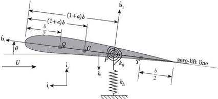
Of interest in such models are points P, C, Q, and T, which refer, respectively, to the reference point (i. e., where the plunge displacement h is measured), the center of mass, the aerodynamic center (i. e., presumed to be the quarter-chord in subsonic thin-airfoil theory), and the three-quarter-chord (i. e., an important chordwise loca­tion in thin-airfoil theory). The dimensionless parameters e and a (i. e., -1 < e < 1 and -1 < a < 1) determine the locations of the points C and P: when these parame­ters are zero, the points lie on the mid-chord, and when they are positive (negative), the points lie toward the trailing (leading) edge. In the literature, the chordwise
offset of the center of mass from the reference point often appears in the equations of motion. It is typically made dimensionless by the airfoil semi-chord b and denoted by xe = e – a. This so-called static-unbalance parameter is positive when the center of mass is toward the trailing edge from the reference point. The rigid plunging and pitching of the model is restrained by light, linear springs with spring constants kh and k.

It is convenient to formulate the equations of motion from Lagrange’s equa­tions. To do this, we need kinetic and potential energies, as well as the generalized forces resulting from aerodynamic loading. We immediately can write the potential

energy as

1 9 1 9

P = 2 khh2 + 2 kee2 (5.15)

To deduce the kinetic energy, we need the velocity of the mass center C, which can be found as

VC = vP + e63 X b [(1 + a) – (1 + e)] bi (5.16)

where the inertial velocity of the reference point P is

v p = – hi2 (5.17)

and thus

vC = —hi2 + be (a – e)b2 (5.18)

The kinetic energy then is given by

11

K = 2mvc ■ vc + 2Ice2 (5.19)

Подпись: 1 Aeroelastic Analysis of a Typical Section Подпись: (5.20)

where Ic is the moment of inertia about C. By virtue of the relationship between b2 and the inertially fixed unit vectors i1 and i2, assuming e to be small, we find that

where Ip = Ic + mb’2×2.

Подпись: VQ = -h 12 + b e Aeroelastic Analysis of a Typical Section Подпись: 62 Подпись: (5.21)

The generalized forces associated with the degrees of freedom h and e are de­rived easily from the work done by the aerodynamic lift through a virtual displace­ment of the point Q and by the aerodynamic pitching moment about Q through a virtual rotation of the model. The velocity of Q is

Подпись: 5P Q = Подпись: Sh 12 + b Se Aeroelastic Analysis of a Typical Section Подпись: 62 Подпись: (5.22)

The virtual displacement of the point Q can be obtained simply by replacing the dot over each unknown in Eq. (5.21) with a S in front of it; that is

Подпись: 5 W = L Подпись: 8h + b Подпись: 2+a Подпись: 80 Подпись: + Mi 80 4 Подпись: (5.23)

where 5pe is the virtual displacement at Q. The angular velocity of the wing is 0b3; therefore, the virtual rotation of the wing is simply 80b3. Hence, the virtual work of the aerodynamic forces is

and the generalized forces become

Qh = —L

(i (5.24)

Q0 = Mi + b ( 2 + aj L

It is clear that the generalized force associated with h is the negative of the lift, whereas the generalized force associated with 0 is the pitching moment about the reference point P.

Подпись: d ҐВK dP dt V d qi ) d qi Подпись: (i = i, 2,n) Подпись: (5.25)

Lagrange’s equations (see the Appendix, Eqs. A.35) are specialized here for the case in which the kinetic energy K depends on only qi, q2,…; therefore

Here, n = 2, qi = h, and q2 = 0 and the equations of motion become

Подпись: IP 0 + mbx0 h + k00 Подпись: Mi + b 4 Aeroelastic Analysis of a Typical Section Подпись: L Подпись: (5.26)

m(h + bx00) + khh = — L

For the aerodynamics, the steady-flow theory used previously gives

Подпись: (5.27)L = 2npIX)bU20 Mi = 0

4

where, in accord with thin-airfoil theory, we have taken the lift-curve slope to be 2n. Assuming this representation to be adequate for now, we can apply the p method because the aerodynamic loads are specified for arbitrary motion. (We subsequently consider more sophisticated aerodynamic theories.)

Подпись: юн Подпись: (5.28)
Aeroelastic Analysis of a Typical Section Aeroelastic Analysis of a Typical Section

To simplify the notation, we introduce the uncoupled, natural frequencies at zero airspeed, defined by

Substituting Eqs. (5.27) into Eqs. (5.26), using the definitions in Eqs. (5.28), and rearranging the equations of motion into matrix form, we obtain

Подпись:0 0

(5.29)

Note that the first equation was multiplied through by b and the variable h was divided by b to make every term in both equations have the same units. Following the p method as outlined previously, we now make the substitutions h = h exp(vt) and в = в exp(vt), which yields

Подпись: (5.30)mb2v2 + mb2a>2h mb2v2 xe + 2nplXJb2U2

Подпись:mb2v2xe Iprn2e + Ipv2 – 2(a + l,)np^b2U2

Aeroelastic Analysis of a Typical Section Aeroelastic Analysis of a Typical Section Подпись: (5.31)

Although this eigenvalue problem can be solved as it is written, it is more convenient to introduce dimensionless variables to further simplify the problem. To this end, we first let v = pU/b, where p is the unknown dimensionless, complex eigenvalue; divide all equations by mU2; and finally introduce the dimensionless parameters

Подпись: p2 + V xe p2 + p ' . xep2 r2p2 + V2 - p(a + 1) Подпись: h b в Подпись: 0 0 Подпись: (5.32)

Here, r is the dimensionless radius of gyration of the section about the reference point P with r2 > x2; a is the ratio of uncoupled plunge and pitch frequencies; p is the mass-ratio parameter reflecting the relative importance of the model mass to the mass of the air affected by the model; and V is the dimensionless freestream speed of the air, sometimes called the “reduced velocity.” As a result, the equations then simplify to

For a nontrivial solution to exist, the determinant of the coefficient matrix must be set equal to zero. There are typically two complex conjugate pairs of roots—for example

bv1 b,

Подпись: (5.33)pi = u = u (Гі ±1 ^x)

bv2 b,

p2 = U = U (Г2 ± 1 ^2)

A more convenient way to present these roots is to multiply them by the reduced velocity V, yielding

Подпись: Vpi Vp2 К, u r1 ^

— (Г1 ± і ^i) -— = — ± і —

Подпись: (5.34)U Ьшє Шв Шв

b,„ , – о л U Г2 . ,Й2

— (Г2 ± i &2)~ = ± i

U Ьшє шв шв

This way, they are now tied to a specified system parameter шв instead of the varying speed U.

For a given configuration and altitude, we must look at the behavior of the complex roots as functions of V and find the smallest value of V to give divergent

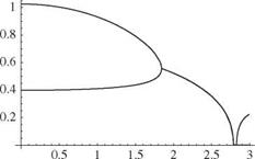
Figure 5.3. Plot of the modal frequency versus V for a = -1/5, e = -1/10, д = 20, r2 = 6/25, and a = 2/5 (steady-flow theory)

Подпись: _Л_ ше Aeroelastic Analysis of a Typical Sectionoscillations in accordance with Table 5.1. That value is VF = UF/{Ъшв), where UF is the flutter speed.

We may find the divergence speed by setting p = 0 in Eq. (5.32), which leads to setting the coefficient of в in the в equation equal to zero and solving the resulting expression for V. This value is the dimensionless divergence speed VD, given by

Подпись:UD _ І д Ьюв Г 1 + 2a

This is the same answer that we would obtain with analyses similar to those presented in Chapter 4.

For looking at flutter, we consider a specific configuration defined by a = -1 /5, e = -1/10, д = 20, r2 = 6/25, and a = 2/5. The divergence speed for this configu­ration is VD = 2.828 (or UD = 2.828 bшв). Plots of the imaginary and real parts of the roots versus V are shown in Figs. 5.3 and 5.4, respectively. The negative of Г is the modal damping and ^ is the modal frequency. We consider first the imaginary parts, Й, as shown in Fig. 5.3. When V = 0, we expect the two dimensionless fre­quencies to be near unity and a for pitching and plunging oscillations, respectively. Even at V = 0, these modes are lightly coupled because of the nonzero off-diagonal terms proportional to xe in the mass matrix. As V increases, the frequencies start to

approach one another, and their respective mode shapes exhibit increasing coupling between plunge and pitch. Flutter occurs when the two modal frequencies coalesce, at which point the roots become complex conjugate pairs. At this condition, both modes are highly coupled pitch-plunge oscillations. The dimensionless flutter speed is VF = UF/(boje) = 1.843 and the flutter frequency is &F/шв = 0.5568. The real parts, Г, are shown in Fig. 5.4 and remain zero until flutter occurs. When flutter occurs, the real part of one of the roots is positive and the other is negative.

Comparing results from this analysis with experimental data, we find that a few elements of realism are at least qualitatively captured. For example, the analysis predicts that flutter occurs at a value of V = VF < VD, which is correct for the specified configuration. Furthermore, it shows a coalescence of the pitching and plunging frequencies as V approaches VF, which is not only correct for the specified configuration but also is frequently observed in connection with flutter analysis. However, the previous analysis is deficient in its ability to accurately predict flutter speed. Moreover, the damping of all modes below the flutter speed is predicted to be zero, which is known to be incorrect. Finally, the steady-flow theory exhibits a coalescence characterized by the two roots being exactly equal to one another at the point of flutter. This condition is not met at all in data obtained from experiments and flight testing.

These deficiencies in predictive capability stem from deficiencies in the aero­dynamic theory. The steady-flow aerodynamic theory of Chapter 4 was used. Al­though this aerodynamic theory has obvious deficiencies (e. g., linearity and two- dimensionality), a most significant deficiency concerning flutter analysis is that it neglects unsteady effects. To obtain an accurate prediction of flutter speed, it is necessary to include unsteadiness in the aerodynamic theory; this demands a more sophisticated aerodynamic theory.

Unfortunately, development of unsteady-aerodynamic theories is no small un­dertaking. Unsteady-aerodynamic theories can be developed most simply when sim­ple harmonic motion is assumed a priori. Although such limited theories cannot be used in the p method of flutter analysis described in Section 5.1, they can be used in classical flutter analysis, described in the next section. As will be shown, classi­cal flutter analysis can predict the flutter speed and flutter frequency, but it cannot predict values of modal damping and frequency away from the flutter condition. To obtain a reasonable sense of modal damping and frequencies at points other than the flutter condition, two approximate schemes are discussed in Section 5.4.

If these approximations turn out to be inadequate for predicting modal damping and frequencies, we have no choice but to carry out a flutter analysis that does not assume simple harmonic motion, which in turn requires a still more powerful aerodynamic theory. One such approach that fits easily into the framework of Sec­tion 5.1 is the finite-state theory of Peters et al. (1995). Such a theory not only facilitates the calculation of subcritical eigenvalues; because it is a time-domain model, it also can be used in control design.

Hence, in the following sections, we first look at classical flutter analysis and the approximate techniques associated therewith and then turn to a more detailed
discussion of unsteady aerodynamics, including one theory that assumes simple harmonic motion (i. e., the Theodorsen theory) and one that does not (i. e., the Peters finite-state theory).

Stability Characteristics from Eigenvalue Analysis

The lifting-surface flutter of immediate concern can be described by a linear set of structural dynamic equations that include a linear representation of the unsteady airloads in terms of the elastic deformations. The surface could correspond to a

wing or stabilizer either with or without control surfaces. Analytical simulation of the surface is sometimes made more difficult by the presence of external stores, engine nacelles, landing gear, or internal fuel tanks. Although such complexities complicate the analysis, they do not alter significantly the physical character of the flutter instability. For this reason, the following discussion is limited to a “clean” lifting surface.

When idealized for linear analysis, the nature of flutter is such that the flow over the lifting surface creates not only steady components of lift and pitching moment but also dynamic forces in response to small perturbations of the lifting-surface motion. The wing airfoil at a local cross section undergoes pitch and plunge motions from lifting-surface torsional and bending deformation, respectively. When a lifting surface that is statically stable below its flutter speed is disturbed, the oscillatory motions caused by those disturbances die out in time with exponentially decreasing amplitudes. That is, we could say that the air provides damping for all such motions. Above the flutter speed, however, rather than damping out the motions due to small perturbations in the configuration, the air can be said to provide negative damping. Thus, these oscillatory motions grow with exponentially increasing amplitudes. This qualitative description of flutter can be observed in a general discussion of stability characteristics based on complex eigenvalues.

Before attempting to conduct an analysis of flutter, it is instructive to first ex­amine the possible solutions to a structural-dynamic representation in the presence of airloads. We presume that a flight vehicle can be represented in terms of its normal modes of vibration. We illustrate this with the lifting surface modeled as a plate rather than a beam. This is more realistic for low-aspect-ratio wings but, in the present framework, this increased realism presents little increase in complexity because of the modal representation. For displacements w(x, y, t) in the z direction normal to the plane of the planform (i. e., the x-y plane), the normal mode shapes can be represented by фі (x, y) and the associated natural frequencies by. A typical displacement of the structure can be written as

n

w(x, y, t) = &(t)фі y) (5.!)

І =1

where &i (t) is the generalized coordinate of the іth mode. For simplicity, both rigid – body and elastic modes are included in this set without special notation to distinguish them from one another. The set of generalized equations of motion for the flight vehicle can be written as

Mi(&i + mf&i) = Si (i = 1, 2,…,n) (5.2)

Stability Characteristics from Eigenvalue Analysis Подпись: (5.3)

where Mi is the generalized mass associated with the mass distribution m(x, y) and can be determined as

The generalized force S (t), associated with the external loading F(x, y, t), can be evaluated as

Si (t) = // F(x, y, t)фі (x, y)dxdy (5.4)

planform

Recall that of the set of natural frequencies ші, any that are associated with rigid-body modes are equal to zero.

To examine the stability properties of the flight vehicle, the only external loading to be considered is from the aerodynamic forces, which can be represented as a linear function of w(x, y, t) and its partial derivatives, plus a set of additional states that may be needed to represent pertinent aspects of the flow field, such as the induced flow or downwash. It is presumed that all other external disturbances have been eliminated. Such external disturbances normally would include atmospheric gusts, store-ejection reactions, and so forth. Recalling that the displacement can be repre­sented as a summation of the modal contributions, the induced-pressure distribution, Ap(x, y, t), can be described as a linear function of the generalized coordinates, their derivatives, and the flow-field states. Such a relationship can be written as

n N

Ap(x, y, t) = [aj ^, y)ij(t) + bj(x, y)lj(t) + Cj(x, y)lj(t^ + J2 dj ^, У)х j(t)

j=1 j=i

(5.5)

where the Xs are state variables associated with the flow field, sometimes called “augmented” states or “lag” states, written here so as to have the same units as the generalized coordinates. The number of these states is denoted by N > 0, which may be distinct from n. The corresponding generalized force of the і th mode now can be determined from

Подпись: U2 Stability Characteristics from Eigenvalue Analysis Подпись: (5.7)

Following the convention in some published work, we factored out the freestream air density px and U2/b2 from the aerodynamic generalized force expression. Although not necessary, this step enables analysts to identify altitude effects more readily. It also shows explicitly that all aerodynamic effects vanish in a vacuum where px vanishes. Moreover, the normalization involving powers of b/U—where b is a reference semi-chord of the lifting surface—allows the matrices [a], [b], [c], and [d] to have the same units, simplifying the equations in terms of dimensionless variables that follow later. Any inhomogeneous terms in the generalized forces can be eliminated by redefinition of the generalized coordinates so that they are measured with respect to a different reference configuration. Thus, the generalized equations of motion can be written as a homogeneous set of differential equations when this form of the generalized force is included. They are

Matrices [A] and [ E] can be obtained from unsteady-aerodynamic theories as well as from computational fluid dynamics or test data. Note that matrix [ E] may be an operator that differentiates {f} one or more times.

This system consists of n + N equations—that is, the number of structural modes (including both elastic and rigid-body modes) plus the number of aerodynamic states, respectively. The general solution to this set of linear ordinary differential equations can be described as a simple exponential function of time because they are homogeneous. The form of this solution is taken as

fi (t) = f i exp(vt) hi (t) = hi exp(vt) (5.10)

Substituting this expression into Eqs. (5.7) and (5.8), we obtain a set of algebraic equations, each term of which contains exp(vt). After factoring out this term, the result is n + N simultaneous linear, homogeneous, algebraic equations for the f s, which may be written in matrix form as

Подпись: 2 b2 2 P2[ M] + —г [' Mm] {f} – Px [p2[c] + p[b] + [a]] {f} – px[d]{X} = {0}

Подпись: (5.11)[P[A] + [I]] Д} – [E] {f} = {0}

where p = bv/U is the unknown dimensionless eigenvalue, and the symbol [M] denotes a diagonal matrix with elements Mi. For a nontrivial solution of the general­ized coordinate amplitudes, the determinant of the array formed by the coefficients of f i and Xi must be zero. It is apparent that this determinant is a polynomial of de­gree 2n + N in p. The subsequent solution of this polynomial equation for p yields 2n + N roots consisting of nc complex conjugate pairs and nr real numbers where 2nc + nr = 2n + N. A typical complex root has the form

vk = —p = Г* ± i Uk k = 1, 2,…,nc (5.12)

whereas the roots vk with к = nc + 1, nc + 2,…,nc + nr are real. In other words, any root can be written as vk so that, ^k = 0 for nc < к < nc + nr.

—(k)

For each root pk, there are corresponding complex column matrices f j, j = 1, 2,…,n, and Xj, j = 1, 2,…, N. Thus, the solution for the displacement field from the generalized equations of motion with the aerodynamic coupling can be written as

Hc +nr

w(x, y, t) = ^ {wk(x, y) exp [(Tk + i&k)tj + Wk(x, y) exp [(Tk – i&k)tj} (5.13)

k=1

where wk is the complex conjugate of wk. This expression for w(x, y, t) turns out to be real, as expected. Each wk represents a unique linear combination of the mode shapes of the structure; viz.

n

Wk(x, y) = ^2 ?(k)^i (x, y) (k = 1, 2,…,nc + nr) (5.14)

i =1

—(k)

Note that only the relative values of f i can be determined unless the initial dis­placement and rate of displacement are specified.

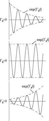
It is apparent from the general solution for w(x, y, t), Eq. (5.13), that the kth component of the summation represents a simple harmonic oscillation that is modi­fied by an exponential function. The nature of this dynamic response to any specified initial condition is strongly dependent on the sign of each Tk. Typical response be­havior is illustrated in Fig. 5.1 for positive, zero, and negative values of Tk when ^k is nonzero. We note that the negative of Tk is sometimes called the “modal damping” of the kth mode, and ^k is called the “modal frequency.” It is also possible to classify these motions from the standpoint of stability. The convergent oscillations when Tk < 0 are termed “dynamically stable” and the divergent oscillations for Tk > 0 are “dynamically unstable.” The case of Tk = 0 represents the boundary between the two and is often called the “stability boundary.” If these solutions are for an aeroelastic system, the dynamically unstable condition is called “flutter” and the stability boundary corresponding to simple harmonic motion is called the “flutter boundary.”

Recall from Eq. (5.13) that the total displacement is a sum of all modal con­tributions. It is therefore necessary to consider all possible combinations of Tk and ^k, where Tk can be < 0, = 0, or > 0 and ^k can be = 0 or = 0. The corresponding

Stability Characteristics from Eigenvalue Analysis
Подпись: Figure 5.1. Behavior of typical mode amplitude when ^k = 0

type of motion and stability characteristics are indicated in Table 5.1 for various combinations of Гк and Qk. Although the primary concern here is in regard to the dynamic instability referred to as flutter, for which ^k = 0, Table 5.1 shows that the generalized equations of motion also can provide solutions to the static-aeroelastic problem of divergence. This phenomenon is indicated by the unstable condition for ^k = 0, and the divergence boundary occurs when Гк = ^k = 0.

In many published works on flutter analysis, the method outlined in this sec­tion based on determination of stability from complex eigenvalues is known as the

Table 5.1. Types of motion and stability characteristics for various values of Гк and Qk

Гк

ttk

Type of motion

Stability characteristic

< 0

= 0

Convergent Oscillations

Stable

= 0

= 0

Simple Harmonic

Stability Boundary

> 0

= 0

Divergent Oscillations

Unstable

<0

= 0

Continuous Convergence

Stable

= 0

= 0

Time Independent

Stability Boundary

>0

= 0

Continuous Divergence

Unstable

Stability Characteristics from Eigenvalue Analysis

Figure 5.2. Schematic showing geometry of the wing section with pitch and plunge spring restraints

“p method.” It is named for the dimensionless complex eigenvalue p = bv/U that appears in Eq. (5.11); p is frequently termed a “reduced eigenvalue.” To provide an accurate prediction of flutter characteristics, the p method must use an aerodynamic theory that accurately represents the loads induced by transient motion of the lifting surface. Depending on the theory, augmented aerodynamic states may or may not be necessary; for example, the theory outlined in Section 5.5.2 uses them, whereas the theory in the next section does not; rather it uses the simplest steady-flow theory for which no claim of accuracy is made. The sole purpose of doing so is to illustrate the use of the p method to analyze a simple configuration.

Aeroelastic Flutter

Подпись: 5The pilot of the airplane… succeeded in landing with roughly two-thirds of his horizontal tail surface out of action; some others have, unfortunately, not been so lucky…. The flutter problem is now generally accepted as a problem of primary con­cern in the design of current aircraft structures. Stiffness criteria based on flutter re­quirements are, in many instances, the critical design criteria. . . . There is no evidence that flutter will have any less influence on the design of aerodynamically controlled booster vehicles and re-entry gliders than it has, for instance, on manned bombers.

—R. L. Bisplinghoff and H. Ashley in Principles of Aeroelasticity, John Wiley and Sons, Inc., 1962

Chapter 3 addressed the subject of structural dynamics, which is the study of phe­nomena associated with the interaction of inertial and elastic forces in mechanical systems. In particular, the mechanical systems considered were one-dimensional, continuous configurations that exhibit the general structural-dynamic behavior of flight vehicles. If in the analysis of these structural-dynamic systems aerodynamic loading is included, then the resulting dynamic phenomena may be classified as aeroelastic. As observed in Chapter 4, aeroelastic phenomena can have a significant influence on the design of flight vehicles. Indeed, these effects can greatly alter the design requirements that are specified for the disciplines of performance, structural loads, flight stability and control, and even propulsion. In addition, aeroelastic phe­nomena can introduce catastrophic instabilities of the structure that are unique to aeroelastic interactions and can limit the flight envelope.

Recalling the diagram in Fig. 1.1, we can classify aeroelastic phenomena as either static or dynamic. Whereas Chapter 4 addressed only static aeroelasticity, in this chapter, we examine dynamic aeroelasticity. Although there are many other dynamic aeroelastic phenomena that could be treated, we focus entirely on the instability called “flutter,” which generally leads to a catastrophic structural failure of a flight vehicle. A formal definition of aeroelastic flutter is as follows: a dynamic instability of a flight vehicle associated with the interaction of aerodynamic, elastic, and inertial forces. From this definition, it is apparent that any investigation of flutter stability requires an adequate knowledge of the system’s structural dynamic and aerodynamic properties. To further elaborate, flutter is a self-excited and potentially destructive
oscillatory instability in which aerodynamic forces on a flexible body couple with its natural modes of vibration to produce oscillatory motions with increasing amplitude. In such cases, the level of vibration will increase, resulting in oscillatory motion with amplitude sufficiently large to cause structural failure.

Because of this, structures exposed to aerodynamic forces—including wings and airfoils but also chimneys and bridges—must be carefully designed to avoid flutter. In complex systems in which neither the aerodynamics nor the mechanical properties are fully understood, the elimination of flutter can be guaranteed only by through testing. Of the various phenomena that are categorized as aeroelastic flutter, lifting – surface flutter is most often encountered and most likely to result in a catastrophic structural failure. As a result, it is required that lifting surfaces of all flight vehicles be analyzed and tested to ensure that this dynamic instability will not occur for any condition within the vehicle’s flight envelope.

If the airflow about the lifting surface becomes separated during any portion of an unstable oscillatory cycle of the angle of attack, the governing equations become nonlinear and the instability is referred to as “stall flutter.” Stall flutter most commonly occurs on turbojet compressor and helicopter rotor blades. Other phenomena that result in nonlinear behavior include large deflections, mechanical slop, and nonlinear control systems. Nonlinear phenomena are not considered in the present treatment. Even with this obvious paring down of the problem, however, we still find that linear-flutter analysis of clean lifting surfaces is complicated. Thus, we can offer only a simplified discussion of the theory of flutter. Readers are urged to consult the references for additional information on the subject.

This chapter begins by using the modal representation to set up a lifting-surface flutter analysis as a linear set of ordinary differential equations. These are trans­formed into an eigenvalue problem, and the stability characteristics are discussed in terms of the eigenvalues. Then, as an example of this methodology, a two-degree – of-freedom “typical-section” analysis is formulated using the simple steady-flow aerodynamic model used in Chapter 4. The main shortcoming of this simple analysis is the neglect of unsteady effects in the aerodynamic model. Motivated by the need to consider unsteady aerodynamics in a meaningful but simple way, we then introduce classical flutter analysis. Engineering solutions that partially overcome the shortcom­ings of classical flutter analysis follow. To complete the set of analytical tools needed for flutter analysis, two different unsteady-aerodynamic theories are outlined: one suitable for use with classical flutter analysis and its derivatives; the other suitable for eigenvalue-based flutter analysis. After illustrating how to approach the flutter analysis of a flexible wing using the assumed-modes method, the chapter concludes with a discussion of flutter-boundary characteristics.

Composite Wings and Aeroelastic Tailoring

In this chapter, we considered divergence and aileron reversal of simple wind-tunnel models; torsional divergence, load redistribution, and aileron reversal in flexible- beam representations of lifting surfaces; roll effectiveness of an airplane with wings modeled as beams; the effects of sweep on coupled bending-torsion divergence; and the role of aeroelastic tailoring. It is clear that aircraft design is strongly influenced by aeroelastic considerations. In all of the cases explored in this chapter, the inertial loads are inconsequential and therefore were neglected. In Chapter 5, inertial loads are introduced into the aeroelastic analysis of flight vehicles, and the flutter problem is explored.

Composite Wings and Aeroelastic Tailoring

Problems

1.

Composite Wings and Aeroelastic Tailoring

Consider a rigid, wind-tunnel model of a uniform wing, which is pivoted in pitch about the mid-chord and elastically restrained in pitch by a linear spring with spring constant of 225 lb/in mounted at the trailing edge. The model has a symmetric airfoil, a span of 3 feet, and a chord of 6 inches. The total lift-curve

slope is 6 per rad. The aerodynamic center is located at the quarter-chord, and the mass centroid is at the mid-chord.

(a) Calculate the divergence dynamic pressure at sea level.

(b) Calculate the divergence airspeed at sea level.

Answers: qD = 150 lb/ft2; UD = 355 ft/sec

2. For the model in Problem 1, for a dynamic pressure of 30 lb/ft2, compute the percentage change in lift caused by the aeroelastic effect.

Answer: 25%

3. For the model of Problem 1, propose design changes in the support system that would double the divergence dynamic pressure by

(a) changing the stiffness of the restraining spring

(b) relocating the pivot point

Answers: (a) к = 450 lb/in; (b) xO = 2.513 in

4. For the model of Problem 1 as altered by the design changes of Problem 3, calculate the percentage change in lift caused by the aeroelastic effect for a dynamic pressure of 30 lb/ft2, a weight of 3 lb, ar = 0.5°, and for

(a) the design change of Problem 3a

(b) the design change of Problem 3b Answers: 11.11%; 17.91%

5. Consider a strut-mounted wing similar to the one discussed in Section 4.1.3, except that the two springs may have different stiffnesses. Denoting the leading – edge spring constant by к1 and the trailing-edge spring constant by к2, and assum­ing that the aerodynamic center is at the quarter-chord, show that divergence can be eliminated if кі/ к2 > 3.

6. Using Excel or a similar tool, plot a family of curves that depict the relationship of the aileron-elastic efficiency, n, versus normalized dynamic pressure, q = q/qD, for various values of R = qR/qD and 0 < q < 1. Make two plots on the following scales to reduce confusion:

(a) Plot R < 1 using axes —3 < n < 3

(b) Plot R > 1 using axes —3 < n < 3

Hint: Do not compute values for the cases in which 1 < R < 1.1; Excel does not handle these well and you may get confused. For some cases, you may want to plot symbols only and nicely sketch the lines that form the curves.

Answer the following questions: Where does aileron reversal occur? If you had to design a wing, what R would you try to match (or approach) and why? What happens when qR = qD? How does the efficiency change as q approaches qR? Why do you think this happens? What other pertinent features can you extract from these plots? Explain how you came to these conclusions.

7. Consider a torsionally elastic (GJ = 8,000 lb in2) wind-tunnel model of a uni­form wing, the ends of which are rigidly fastened to the wind-tunnel walls. The model has a symmetric airfoil, a span of 3 feet, and a chord of 6 inches.

The sectional lift-curve slope is 6 per rad. The aerodynamic center is located at the quarter-chord, and both the mass centroid and the elastic axis are at the mid-chord.

(a) Calculate the divergence dynamic pressure at sea level.

(b) Calculate the divergence airspeed at sea level.

Answers: (a) qD = 162.46 lb/ft2; (b) UD = 369.65 ft/sec

8. For the model in Problem 7, propose design changes in the model that would double the divergence dynamic pressure by

(a) changing the torsional stiffness of the wing

(b) relocating the elastic axis Answers: GJ = 16,000 lb in2; xea = 2.25 in

9. For the model of Problem 7, for a dynamic pressure of 30 lb/ft2, compute the percentage increase in the sectional lift at mid-span caused by the aeroelastic effect.

Answer: 28.09%

10. For the model in Problem 7, for a dynamic pressure of 30 lb/ft2, compute the percentage increase in the total lift caused by the aeroelastic effect.

Answer: 18.58%

11.

Composite Wings and Aeroelastic Tailoring

Consider a swept clamped-free wing, as described in Section 4.2.6. The governing partial differential equations are given in Eqs. (4.94) and the boundary condi­tions in Eqs. (4.95). An approximate solution is sought for a wing with a symmet­ric airfoil, using a truncated set of assumed modes and the generalized equations of equilibrium: a specialized version of the generalized equations of motion for which all time-dependent terms are zero. Note that what is being asked for here is equivalent to the application of the Ritz method to the principle of virtual work (see Section 3.5). With the wing weight ignored, only structural and aero­dynamic terms are involved. The structural terms of the generalized equations of equilibrium are based on the potential energy (here, the strain energy) given by

Composite Wings and Aeroelastic Tailoring

and the bending and torsion deformation is represented in terms of a truncated series, such that

where Nw and No are the numbers of assumed modes used to represent bending and torsion, respectively; n and фі are the generalized coordinates associated with bending and torsion, respectively; and Уі and &і are the assumed mode

shapes for bending and torsion, respectively. Determine the potential energy in terms of the generalized coordinates using as assumed modes the uncoupled, clamped-free, free-vibration modes of torsion and bending. For torsion

Подпись:n (j- 2) у

£

For bending, according to Eq. (3.258), is given as

= cosh(a y) – cos(^y) – ві [sinh^y) – sin^y)]

with ai and ві as given in Table 3.1.

12.

Composite Wings and Aeroelastic Tailoring

Work Problem 11, but for assumed modes, instead of using the expressions given therein, use

recalling that these functions are not orthogonal.

13. Work Problem 11, but use the finite element method to represent both bending and torsion.

14. Referring to Problem 11,12, or 13, starting with the virtual work of the aero­dynamic forces as

__ r£ _

s w = (l’sw + me) dy

J0

where L and M are the sectional lift and pitching-moment expressions used to develop Eqs. (4.94), assuming a symmetric airfoil and using the given deformation modes, find the generalized forces Ei, і = 1, 2,…, N = Nw + Ne. As discussed in the text, generalized forces are the coefficients of the variations of the generalized coordinates in the virtual-work expression. (Hint: Neglecting the weight terms on the right-hand sides of Eqs. 4.92, we find L is the right-hand side of the second of those equations, whereas M is the negative of the right-hand side of the first and equal to eL.)

15. Referring to Problems 14 and 11,12, or 13, determine the generalized equations of equilibrium in the form

[*rn }=q {[ i + {S0i}

where q is the dimensionless dynamic pressure given by q/qD0; qD0 is the tor­sional divergence dynamic pressure of the unswept clamped-free wing, given by Eq. (4.55); {f} is the column matrix of all unknowns Пі = П /£, і = 1, 2,…, Nw, and фі, i = 1,2,…, Ne; and {H0} is an N x 1 column matrix containing the parts of the aerodynamic generalized forces that do not depend on any unknowns; and N = Nw + Ne. (Note that in application of the finite element, Nw = Ne refers to the number of finite elements, and N = 2Nw + Ne.) The N x N matrices [K]
and [A] are the stiffness and aerodynamic matrices, respectively. If Problem 11 is the basis for solution and elastic coupling is ignored, then the stiffness matrix [K] is diagonal because the normal modes used to represent the wing structural behavior are orthogonal with respect to the stiffness properties of the wing.

16. Referring to Problem 15, perform the following numerical studies:

a. Divergence: To determine the divergence dynamic pressure, write the homogeneous generalized equations of equilibrium in the form

1

=R} = [ K]-1[ A]R} q

which is obviously an eigenvalue problem with 1/q as the eigenvalue. After solving the eigenvalue problem, the largest 1/q provides the lowest dimensionless critical divergence dynamic pressure qD = qD/qD0 at the sweep angle under consideration. By numerical experimentation, determine Nw and Ne to obtain the divergence dynamic pressure to within plotting accuracy. Plot the divergence dynamic pressure versus sweep angle for a range of values for the sweep angle -45° < Л < 45° and values of the dimensionless parameters e/t (0.05 and 0.1), EI/GJ (1 and 5), and к = 0, ±0.5. Compare your results with those obtained in Eq. (4.129). Comment on the accuracy of the approximate solution in the text versus your Ritz or finite element solution. Which one should be more accurate? Discuss the trends of divergence dynamic pressure that you see regarding the sweep angle, stiffness ratio, and location of the aerodynamic center.

b. Response: For the response, you need to consider the inhomogeneous equations, which should be put into the form

[[K] – q[ A]] {£} = q {30}

Letting ar = 1°, obtain the response by solving the linear system of equations represented in this matrix equation. Plot the response of the wing tip (i. e., w and в at y = t) for varying dynamic pressures up to q = 0.95qD for the above values of e/t, EI/GJ, and к with Л = -25° and 0°. Plot the lift, twist, and bending-moment distributions for the case with the largest tip-twist angle. Comment on this result and on the trends of static-aeroelastic response that you see regarding the sweep angle, stiffness ratio, location of the aerodynamic center, and elastic coupling.

17. Consider the divergence of an unswept composite wing with к = 0, GJ/EI = 0.2, and e/t = 0.025. Using Eq. (4.126), determine the value of к, as defined by Eq. (4.125), needed to keep the divergence dynamic pressure unchanged for forward-swept wings with various values of Л < 0. Plot these values of к versus Л.

18. Using the approximate formula found in Eq. (4.126), derive a formula for qDact3/EI analogous to Eq. (4.113) and use it to determine the divergence dynamic pressure for swept composite wings when e < 0. Discuss the situations in which we might encounter a negative value of e. Which sign of к would you
expect to be stabilizing in this case? Plot this normalized divergence dynamic pressure for a swept composite wing with GJ/EI = 0.2 and ell = -0.025 versus Л for к = 0 and ±0.4.

19.

Подпись: в" + тв — r T Подпись: =0
Composite Wings and Aeroelastic Tailoring

Consider the divergence of a swept composite wing. Show that the governing equation and boundary conditions found in Eqs. (4.120) and (4.121) can be written as a second-order, integro-differential equation of the form

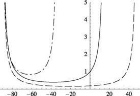
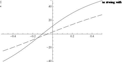
with boundary conditions в(0) = в'(1) = 0 and with r = в/т. Determine the two simplest polynomial comparison functions for this reduced-order equation and boundary conditions. Use Galerkin’s method to obtain one – and two-term approximations to the divergence dynamic pressure td versus r. Plot your approximate solutions for the case in which GJ/EI = 0.2, e/l = 0.02, and к = -0.4, depicted in Fig. 4.28, and compare these with the approximate solu­tion given in the text. For the two-term approximation, determine the limit point for positive e, noting that the exact values are r = 1.59768 and тD = 10.7090. Answer: The one-term approximation is

30

TD = 12 — 5r

The two-term approximation is

_ _________________ Ш0_________________

TD = 282 — 105r ± V3y15r(197r — 1,036) + ЦЇШ
Composite Wings and Aeroelastic Tailoring
The approximate limit point in the first quadrant is at r = 1.61804 and td = 11.2394. Within plotting accuracy, the two-term approximation is virtually indistinguishable from the exact solution when —10 < td < 10.

21. Consider a rigid body that represents the fuselage of a symmetric aircraft, to which are attached uniform, torsionally flexible wings that have the same properties as those in Problem 20. Assuming the aircraft is flying at constant speed with a constant roll rate, develop solutions for the same sets of parameters as asked for in Problem 20.

Composite Wings and Aeroelastic Tailoring

Aeroelastic tailoring is the design of wings using the directional properties of com­posite materials to optimize aeroelastic performance. The concept of aeroelastic tailoring is relatively new and came into the forefront during the design of forward – swept wings in the 1980s. Equation (4.112) shows that qD drops dramatically for forward-swept, untailored wings. The low divergence speed was a major hurdle in the design of wings with forward sweep. As discussed in this section, use of compos­ite materials can help remove the disadvantages of forward sweep. Currently, aero – elastic tailoring is an integral part of the design of composite wings and can be used to improve performance in a variety of ways.

Composite materials are anisotropic, which implies different material charac­teristics (e. g., stiffness) in different directions. A simple beam model is helpful in developing an understanding of the behavior of composite wings. Such models may exhibit bending-torsion elastic coupling. Analysis of beams with elastic coupling is more involved, but it leads to helpful results.

Let us introduce such coupling in our beam equations. For anisotropic beams with bending-torsion coupling, the “constitutive law” (i. e., the relationship between

Подпись: to

cross-sectional stress resultants and the generalized strains) changes from

where K is the bending-torsion coupling stiffness (with the same dimensions as EI and GJ) and ()" indicates the derivative with respect to y. A positive value of K means that a positive bending deflection will be accompanied by a nose-up twist of the wing, which is normally destabilizing for cases with the elastic axis behind the aerodynamic center.

Using the coupled constitutive law, the equations of equilibrium become

(GJв – Kw") = – qecaa – qc2cmac + Nmgd V,, (4.116)

^EIw" – Ke ^ = qcaa – Nmg

Consider again a wing that is clamped at the root and free at the tip, so that the boundary conditions that must be imposed on the solution are
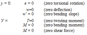
Подпись: y = 0: в = 0 (zero torsional rotation) w=0 (zero deflection) w' = 0 (zero bending slope) У = T=0 (zero twisting moment) M = 0 (zero bending moment) M = 0 (zero shear force) (4.117)

For composite beams, the offsets d and e may be defined in a manner similar to the way they were defined for isotropic beams: d is the distance from the y axis to the cross-sectional mass centroid, positive when the mass centroid is toward the leading edge from the y axis; and e is the distance from the y axis to the aerodynamic center, positive when the aerodynamic center is toward the leading edge from the y axis. Recall that for composite beams, the y axis must have different properties from those it has for isotropic beams, and the term “elastic axis” has a different meaning. For a spanwise uniform isotropic beam, the elastic axis is along the y axis and is the locus of cross-sectional shear centers; transverse forces acting through this axis do not twist the beam. For spanwise uniform composite beams with bending-twist coupling, no axis can be defined as the locus of a cross-sectional property through which transverse shear forces can act without twisting the beam. For such beams, we must place the y axis along the locus of shear centers, a point in the cross section at which transverse shear forces are structurally decoupled from the twisting moment. Although transverse shear forces acting at the y axis do not directly induce twist, the bending moment induced by the shear force still induces twist when K = 0.

Composite Wings and Aeroelastic Tailoring

Differentiating the first equation with respect to y and transforming the set of equa­tions so that they are uncoupled in the highest derivative terms вand w"", we obtain

Composite Wings and Aeroelastic Tailoring Подпись: (4.120)

Multiplying the first equation by cos(A) and the second equation by sin(A) and subtracting the second equation from the first, we obtain a single equation in terms of в = в cos(A) – w’ sin(A) as

where ()’ now denotes d( )/dn as in the parallel development for the elastically uncoupled wing discribed previously.

Подпись: в (0) = в '(1) Composite Wings and Aeroelastic Tailoring Подпись: K 1 - = tan(A) EI Подпись: в(1) = 0 (4.121)

The boundary conditions can be derived from Eqs. (4.117) as

Composite Wings and Aeroelastic Tailoring Подпись: (4.122)

The aeroelastic divergence problem with structural coupling has the same math­ematical form as the problem without coupling, an approximate solution of which is given in the previous section. We can see that the parameters т and в can be redefined as

and, again, the divergence boundary can be expressed approximately in terms of the line

Подпись: 22

Подпись: (4.123)т» = T +16eD

Подпись: QD Подпись: n2 EI GJ _ K2 GJ EIGJ ecal2 cos2 (Л) b _ к tan(A) Composite Wings and Aeroelastic Tailoring Подпись: tan(Л) _ m]}

Using the expressions for the parameters in the equation of the divergence boundary, we have

(4.124)

Подпись: к Подпись: K GEIGJ Подпись: (4.125)

We can simplify this by introducing the dimensionless parameter

Composite Wings and Aeroelastic Tailoring
so that

Подпись: tan^TO) Composite Wings and Aeroelastic Tailoring Подпись: (4.128)

As before, when the denominator of the expression for divergence dynamic pres­sure vanishes, it corresponds to infinite divergence dynamic pressure; crossing this “boundary” means crossing from a regime in which divergence occurs to one in which it does not. Setting the denominator to zero and solving for the tangent of the sweep angle, we obtain

where Лто is the sweep angle at which the divergence dynamic pressure goes to infinity. With this definition, we can rewrite Eq. (4.127) as

(4.129)

Again, divergence is possible only if -90° < Л < Лто. Thus, because of the presence of к as an additional design parameter, designers can at least partially compensate for the destabilizing effect of forward sweep by appropriately choosing к < 0, which for an increment of upward bending of the wing provides an increment of nose-down twisting. There is a limit to how much coupling can be achieved, however, because typically |k| < 0.86.

Чр

4d0

Composite Wings and Aeroelastic Tailoring

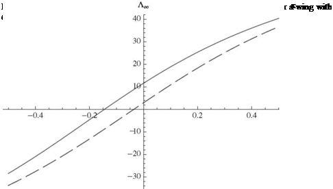
Figure 4.28. Normalized divergence dynamic pressure for an elastically coupled, swept wing with GJ/EI = 0.2 and e/t = 0.02; к = —0.4 (dots and dashes), к = 0 (solid lines), к = 0.4 (dashed lines)

There are two main differences between the designs of isotropic and compos­ite wings. First, it is possible to achieve a much wider range of values for GJ/EI. Second—and significantly more powerful—is the fact that composite wings can be designed with nonzero values of к. From Eq. (4.128), the value of Лто is decreased as к is decreased, which means that the range of Л over which divergence occurs is decreased. To confirm this and the previous statement about positive к being destabilizing, Fig. 4.28 shows results for к = -0.4, 0, and 0.4. It is clear that a com­posite wing can be swept forward and still avoid divergence with a proper choice (i. e., a sufficiently large and negative value) of к. Because forward sweep has ad­vantages for the design of highly maneuverable aircraft, this is a result of practical importance. The sweep angles at which divergence becomes impossible, Лто, are also somewhat sensitive to GJ/EI and e/t, as shown in Figs. 4.29 and 4.30. Ev­idently, divergence-free, forward-swept wings may be designed with larger sweep angles by decreasing torsional stiffness relative to bending stiffness and by decreas­ing e/t.