Category MECHANICS. OF FLIGHT

Convergent-divergent nozzle

Let us now consider the flow through a contracting-expanding duct, a conver­gent-divergent nozzle, a de Laval nozzle – at any rate a constriction in a duct; or, as we called it in the low speed case, a venturi meter.

It is true that there are variations in the shapes of these devices according to what they are required to do, and according to the speed of flow with which they have to deal, but all have this in common – that they converge from the inlet to a throat, then diverge to the outlet.

We are familiar by now with the picture which illustrates subsonic flow through a venturi tube (Fig. 2.6); in the contracting portion the streamlines converge, the airflow accelerates, the pressure falls and, although the change in density is small (so small that we could then afford to neglect it), it is a decrease, i. e. the air is rarefied. In the expanding duct, beyond the throat, the streamlines diverge, the airflow decelerates, the pressure rises, and such small change in density as may occur is an increase, i. e. the air is compressed.

What happens if we gradually speed up the flow through the venturi tube? The reader can probably answer that from what we have discovered first about transonic flow, then about supersonic flow.

Подпись: New Old Mach Line

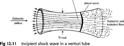
The first thing that will happen is that when the airflow, at the throat, reaches the speed of sound, a shock wave will be formed just beyond the throat just as it was on the camber of an aerofoil; so instead of the gradual rise in pressure and fall in speed beyond the throat, there will be a sudden rise in pressure, a sudden fall in speed, and the flow behind the shock wave will

Fig 12.10 Supersonic flow over double wedge at angle giving maximum L/D

Supersonic

Convergent-divergent nozzle

become turbulent (Fig. 12.11). The front portion of the venturi will still func­tion reasonably like a venturi, i. e. the velocity will increase and the pressure fall, but the rear portion will no longer serve its proper purpose.

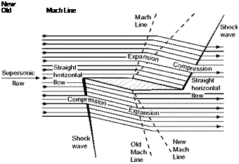
It is interesting to note that if the upstream flow is subsonic then at the throat the speed can never be greater than the speed of sound. If the flow does reach this speed it may then accelerate to supersonic speed downstream of the throat (Fig. 12.11). In this condition the duct is said to be choked. If the downstream pressure is reduced the supersonic region extends and the shock moves out of the divergent section.

If the flow in the duct ahead of the contraction is supersonic, we find that the flow behaves in the opposite way! This time the speed reduces in the con­vergent section and increases in the divergent section, reaching a minimum value at the throat (Fig. 12.12). The increase in speed is still, however, accom­panied by a decrease in pressure and vice versa.

Supersonic flow over an aerofoil

We are now in a position to look at the supersonic flow over an aerofoil – but what is to be the shape of our supersonic aerofoil?

Since straight lines and sharp corners seem to be at least as good as curves, the simplest aerofoil section for supersonic speeds would seem to be a flat plate inclined at a small angle of attack, and there is no doubt that if it were poss­ible to give adequate strength to such a plate it would be the obvious answer.

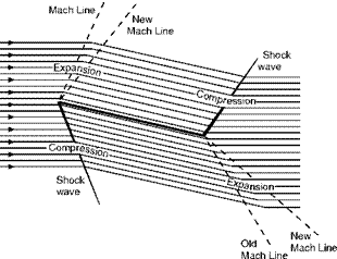
If the plate were thin enough the flow would be undisturbed at zero angle of attack – and of course there would be no lift. At a small angle, on the top surface there would be an expansion wave at the leading edge and a shock wave at the trailing edge, and on the bottom surface a shock wave at the leading edge and an expansion wave at the trailing edge, the flow being as in Fig. 12.8.

On the top surface, owing to the expansion wave at the leading edge, the flow would be speeded up and there would be a decreased pressure; on the bottom surface, owing to the shock wave at the leading edge, the flow would be slowed down, and there would be an increased pressure. So there would be lift – and drag.

But a flat plate is clearly not a practical proposition, so let us have a look at a shape that is – the double-wedge.

First let us see what happens at zero angle of attack (Fig. 12.9, overleaf).

Подпись: Supersonic flow Supersonic flow over an aerofoil

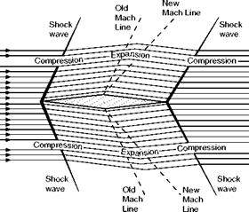
The pattern of shock waves and expansions will, of course, be the same on both top and bottom surfaces. At the nose (which corresponds exactly to the small-angled wedge of Fig. 12.4) there will be shock waves, and the conse­quent increases in pressure, density, and temperature, and a decrease in

Supersonic

flow


Supersonic flow over an aerofoil

Fig 12.9 Supersonic flow over double-wedge at zero angle of attack velocity; at the point of maximum camber there will be the expansions, and the corresponding changes over the rear portion of the aerofoil; at the trailing edge, though not perhaps quite so obvious, there will again be the wedge effect, shock waves on both surfaces, and again the changes of pressure, density, temperature, and velocity.

At very small angles of attack, for reasons that should now be quite clear, the bow shock wave on the upper surface becomes less intense and that on the lower surface more intense; the tail shock wave, on the other hand, becomes more intense on the upper surface and less intense on the lower surface. But one of the most interesting, and perhaps surprising, features of the flow is that there is no upwash in front of the aerofoil (how can there be when the airflow doesn’t know that the aerofoil is coming?) – and no down wash behind the aerofoil; the deflection of the air is only between the shock waves. The pressure distribution over the aerofoil accounts for both lift and drag – as it did with the flat plate, which also caused neither upwash nor downwash. After all, a speedboat travelling through the water causes a considerable depression (and rising) of the water as it passes, but it does not leave a permanent dent!

When the angle of attack reaches that at which the front portion of the top surface is parallel to the approaching airflow (an important condition because it gives the maximum lift/drag ratio for this type of aerofoil) the bow shock wave on the upper surface, and the tail shock wave on the lower surface, both disappear – as one would expect (Fig. 12.10).

At a still larger angle – but the reader may like to draw this for himself. Eventually, as the angle of attack is increased, the bow wave will become detached, as it always is in front of a blunt nose.

The reader should have no difficulty in sketching the flow patterns for other shapes (such as those in Figs 12.20, 12.21, and 12.22), and at various angles.

Expansive flow

There is, however, another way in which a supersonic flow can turn corners.

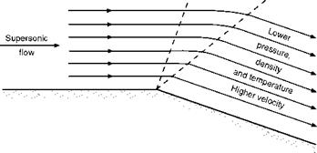
To understand this let us consider what happens at a convex corner, i. e. one at which, if the flow were to go straight on, it would get farther away from the surface (Fig. 12.6).

Figure 12.7 shows the result, though it must be admitted that it doesn’t really indicate the reason for what happens – this unfortunately can only be given in a mathematical treatment of the subject.

Expansive flow

Fig 12.5 Change of direction and speed of flow

Подпись: AirflowПодпись:Подпись: Old Mach Line Expansive flowFig 12.6

New

Mach Line

Expansive flow


As we can see from the figures the supersonic airflow, on meeting a corner of this type, is free to expand; this it does, becoming more rarefied, i. e. decreasing in density in the decreased pressure, and the lines of flow are there­fore farther apart, and the temperature also falls as is usual in an expanding flow. The speed on the other hand increases.

So far it seems very similar to compressive flow – except that all the oppo­sites happen! There is, however, another fundamental difference which is illustrated on the figure though it may not be immediately obvious. The dotted lines indicate the slopes of the two Mach Tines, the first one for the velocity of flow before the corner, the second one after the corner; notice that the second one is at a more acute angle to the new surface than the first one is to the orig­inal surface, i. e. that the angle between the Mach Tines is greater than the change of angle of the surface – this of course is because the velocity after the corner is greater than before the corner. But more important than this is to notice that between the Mach Tines the flow changes gradually on a curved path, not suddenly as at a shock wave, because the Mach Tines no longer con­verge as in Fig. 12.2c, but, on the contrary, they now diverge.

This gradual change of flow helps to emphasise the fact that the Mach Tines are nothing like shock waves; for there is some danger that even the dotted lines in the figures may suggest that they are. If we go back to the original explanation of Mach Tines, it will be realised that, in comparison with shock waves, they are small weak waves that may appear anywhere along the surface, not just at corners, and that the flow passes through them without sudden changes in its direction or physical properties.

This type of flow is called expansive flow, and the phenomenon at the corner which causes the flow to change is sometimes called an expansion wave.

It should be noted that although the change at an expansion wave is gradual when compared with that at a shock wave, it still takes place over a very short time and distance compared with subsonic flow in which things happen long before – and long after – the corner is reached.

It should be noted, too, that although there is a limit to the angle through which supersonic flow can be turned at one expansion wave, it is possible to turn it through a large angle by a succession of expansion waves. In fact, of course a curved surface is an infinite series of corners, and over a convex curved surface there will be a succession of expansion waves, and the changes in direction of the flow, and in pressure, density, and temperature will be even more gradual, though still, unlike subsonic flow, being confined to the passage over the surface itself, and not before or after. So, although supersonic flow can turn sharp corners, it should not be thought that it cannot also be per­suaded to pass over curved surfaces, and this is a very good thing because even supersonic aeroplanes sometimes have to fly slowly and curved surfaces are very much better for low speeds.

Compressive flow

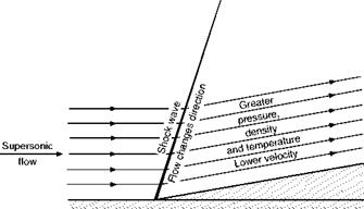
Tet us consider first what happens when supersonic flow meets what we have called a concave corner, or putting it more practically, a sharp, small-angled wedge. One way of describing this kind of corner is to say that if the flow were to go straight on it would intersect the body (Fig. 12.3).

Figure 12.4 (overleaf) shows what happens. The flow will in fact go straight on until it hits something – but what it hits will not be the wedge itself, but the shock wave which is formed by the slowing up of the flow as a result of the point of the wedge being inserted in the flow, and the consequent converging of the Mach Tines (perhaps that wasn’t such a bad explanation after all).

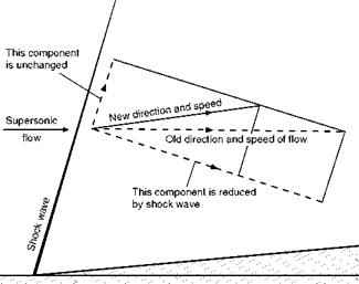
In this type of flow there will be an inclined or oblique shock wave. Now it has already been explained that a shock wave at right angles to the flow causes a sudden reduction in the speed of flow, but a shock wave oblique to the flow causes both a reduction in the magnitude of the velocity, and a change in its direction. The change of direction is a result of the fact that it is only the com­ponent of the velocity at right angles to the shock wave which is reduced; the

Compressive flow

Compressive flow

Fig 12.4 Compressive flow other component (along the shock wave) remains unchanged in passing through the shock wave. This is illustrated in Fig. 12.5, and it is clear that the new direction of flow will be parallel to the new surface.

So the flow has turned the corner; the change of direction was sudden and occurred entirely at the shock wave. The flow after the corner is at a reduced velocity (though it may still be supersonic), the lines of flow are closer together, the pressure is higher, the density is higher (the air is compressed, possibly quite appreciably), and the temperature is higher. The Mach Tines, at the lower speed, will be more steeply inclined to the new surface.

Supersonic flow most commonly compresses through a shock wave; and at the leading edge of a wing, or the nose of a body, or at the mouth of a con­tracting duct, there is – as at this wedge – no gradual change of pressure as with subsonic flow, but a sudden rise in pressure, density, and temperature, and a sudden fall in velocity. This type of flow is called compressive flow. By very careful design it is possible to obtain a gradual compression by avoiding the conditions where the Mach Tines coalesce (Fig. 12.2(c)). The shock com­pression is, though, much more usual.

Supersonic flow

There are fundamental differences between supersonic flow and subsonic flow, and perhaps these differences are best illustrated by the different ways in which the two kinds of flow turn corners, or – what comes to much the same thing – pass through contracting or expanding ducts.

Although we may not have put it in that way we have already studied this in the case of subsonic flow; and perhaps we may sum up the results by saying –

1. That subsonic flow anticipates the corner or whatever it may be, and so the pattern of the flow changes before the corner is reached.

2. That the change of flow takes place gradually on curved paths.

3. That at what we might call a concave comer, or in a contracting duct, the flow speeds up and the pressure falls.

4. That at what we might call a convex corner, or in an expanding duct, the flow slows down and the pressure rises.

There are of course complications (as, for instance, if we overdo the sudden­ness of the change and the flow breaks away from the surface), but in the main we have established these four principles, and have seen numerous examples of how they are applied in practice.

Now let us look at supersonic flow.

We have already made it sufficiently clear that the first principle is different – and we have explained why it is different. Supersonic flow does not, and cannot, anticipate a corner or anything else that lies ahead, because there is no means by which it can know that it is there.

What, then, of the other three principles?

Mach angle

Figure 11.2 illustrated the piling up of the air in front of a body moving at the speed of sound, and explained how the incipient shock wave is formed. This incipient shock wave is at right angles to the direction of the airflow, and this means as near as matters at right angles to the surface of a body such as a wing.

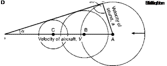
Now suppose a point is moving at a velocity У (which is greater than the speed of sound) in the direction A to D (Fig. 12.1). A pressure wave sent out when the point is at A will travel outwards in all directions at the speed of sound; but the point will move faster than this, and by the time it has reached D, the wave from A and other pressure waves sent out when it was at В and C will have formed circles as shown in the figure, and it will be possible to draw a common tangent DE to these circles – this tangent represents the limit to which all these pressure waves will have got when the point has reached D.

Now AE, the radius of the first circle, represents the distance that sound has travelled while the point has travelled from A to D, or, expressing it in veloc­ities, AE represents the velocity of sound – usually denoted by a – and AD represents the velocity of the point У.

Подпись:Speed of point _ V Speed of sound a

(as illustrated in the figure this is about 2.5).

Mach angle

The angle ADE, or a, is called the Mach Angle and by simple trigonometry it will be clear that

Mach angle

in other words, the greater the Mach Number the more acute the angle a. At a Mach Number of 1, a of course is 90°.

Fig 12.1 Mach angle

Mach angle

If the moving point is a solid 3-dimensional body, such as a bullet, a com­plete cone – called the Mach Cone – will be formed, the angle at the apex being 2a. If the moving point represents a straight line such as the leading edge of a wing, a wedge will be formed, again with an angle 2a at the leading edge.

The tangent line DE is called a Mach Line, and it clearly represents the angle at which small wavelets are formed; the velocity of the airflow can even be calculated by measuring the angle on photographs of the wavelets.

Again the hydraulic analogy may be useful, since similar effects are seen when a ship passes through water or a thin stick is placed in a fast-moving stream of water. Only the region within the wedge formed by the bow waves is affected by the stick; the water outside this region flows on as if nothing was there. And the faster the flow, the sharper is the angle of the wedge.

It might be thought that the Mach Line represented the inclination of the shock waves – but this is not so. Disturbances of small amplitude travel at the speed of sound, but shock waves, which are waves of larger amplitude, actu­ally travel slightly faster than sound, and therefore they form at a rather larger angle to the surface. This fact is difficult to explain without going into the mathematics of fluid flow, which is quite beyond the scope of this book, but the following explanation of how shock waves are formed may help us to understand how their slope is determined.

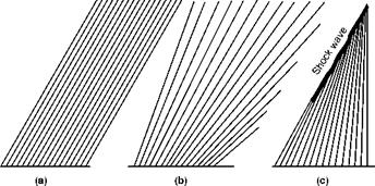
Imagine a supersonic flow of air over a flat surface. This surface can never be perfectly smooth, and may be considered as consisting of a very large number of particles or slight bumps. At each of these bumps a Mach Line will be formed; its angle to the surface depending on the speed of the flow in accor­dance with the formula sin a = 1/M.

If the speed of flow remains constant, the Mach Lines will all be parallel as in Fig. 12.2a (overleaf).

If the speed of flow is accelerating, the Mach Lines will diverge as the angle becomes more acute with the increasing speed (Fig. 12.2b).

But if the speed of flow is decelerating the Mach Lines will converge, add up as it were, and form a more intense disturbance or wave, one of greater amplitude (Fig. 12.2c).

This is one way of explaining how a shock wave is formed at all, but it also gives some indication of how its slope is determined. Unfortunately it is not very convincing from this point of view, and it could even be argued that the slope of the shock wave is less steep than some of the Mach Lines. Also, is a shock wave formed because the air is slowing up, or is it the shock wave that slows up the flow?

Fig 12A Flight at supersonic speed (opposite)

(By courtesy of the Lockheed-California Company, USA)

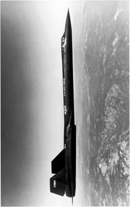
The SR-71 Blackbird was capable of flight at Mach numbers in excess of 3. Delta wings with high leading-edge sweep, lifting chines on the forward fuselage, and two turbo-ramjet engines: bypass turbojets that effectively function as ramjets in high-speed flight.

Mach angle

Fig 12.2 Mach lines and shock wave

(a) Speed of flow constant.

(b) Accelerating flow.

(c) Decelerating flow.

So perhaps we must fall back on the argument that shock waves travel faster than sound, and even more on the fact that the shock wave is at a steeper angle than the Mach Lines, for very fortunately that it is a fact can easily be seen on photographs; e. g. in Fig. 11B it is clear that the bow and tail main shock waves are at a coarser angle than the small wavelets which result from small pressure disturbances due to the surface roughness.

Other examples of the practical effect of large disturbances travelling faster than the speed of sound are the hearing of sonic bangs before the noise of the aircraft, and the way in which the shock wave of an explosion is followed by the other noises.

But has all this got any practical significance in aircraft design? Yes, as a matter of fact, it has; but to understand what the practical significance is we must study the nature of supersonic flow.
Flight at supersonic speeds

Introduction

As explained in the previous chapter subsonic, transonic and supersonic flight merge one into the other, and it is not easy to define where one ends and the other begins. But the change from subsonic to transonic does at least involve some outward and visible signs – in the laboratory there is the formation of shock waves, and in flight there is the shock stall with its varying effects according to the type of aircraft – whereas the change from transonic to super­sonic is not accompanied by any such signs whether in the laboratory or the air, so the dividing line between the two is even more vague. In general we can only say that supersonic flight begins when the flow over all parts of the aero­plane becomes supersonic. But at what Mach Number does that happen? Does it in fact ever happen? Are there not always likely to be one or two stagnation points? And what about the boundary layer where the flow near the surface is certainly subsonic? Perhaps after all it is better to say at about Ml.2, or 1.5, or maybe 2? Figure 12A (overleaf) illustrates an aircraft designed for super­sonic speeds.

Supersonic shock pattern

We have already had a look at the supersonic shock pattern in Fig. 11.12e, and except that the angles of shock waves become rather more acute as the speed increases there is very little change in this pattern over the supersonic range of speeds. To see why the angles of the shock waves change, we must understand the meaning and significance of the Mach Angle.

Other devices to prevent or delay separation

There are several other devices which have been used to prevent or delay sep­aration of the boundary layer, and so allay the rapid increase in drag at the sonic barrier, or the buffeting, or violent changes in trim which are liable to occur as a result of shock waves or separation, or some or all of these troubles.

Other devices to prevent or delay separation

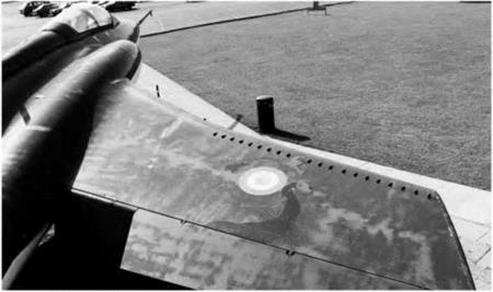
Fig 1 ID Vortex generators

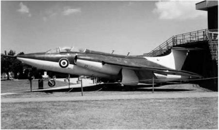
The Buccaneer again, showing vortex generators on the outer wing. This ‘fix’ was used to improve wing flow attachment on many early swept-wing aircraft.

Other devices to prevent or delay separation
A thickened trailing edge is sometimes employed; this causes vortices which have much the same effect as those created by vortex generators, though natu­rally the effect is not felt so far forward on the wing surface.

On heavily swept-back wings fences (Figs 11.22) are often fitted; these are vanes of similar height to vortex generators, but running fore and aft across the top surface of the wing, and designed to check any spanwise flow of air along the wing, for this in turn is likely to cause a breakaway of the flow near the wing tips and so lead to tip stalling, particularly on swept wings.

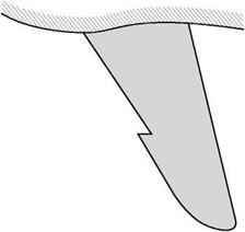
Another problem with highly swept wings is the tendency for the flow to separate in the tip region first. This causes all sorts of problems, for example large changes in pitching moment. This effect may be reduced by introducing a notch or saw-tooth in the leading edge (Figs 11.23 and HE). The notch also generates a strong vortex which controls the boundary layer in the tip region.

Leading-edge droop and leading-edge flaps are becoming quite common features of high-speed aircraft, but these are to prevent separation of the flow at the low-speed end of the range, i. e. at large angles of attack, and so help to solve one of the main problems of aircraft designed for transonic and super­sonic speeds, that of making them fly safely slowly. A permanent droop is called leading-edge droop or droop-snoot; when it is adjustable it is called a leading-edge flap. Either may be combined with trailing-edge flaps and other devices, and Fig. 11.24 (overleaf) illustrates a combination of leading-edge droop, double slotted trailing-edge flaps, and air brakes – all helping to the same end.

Other devices to prevent or delay separation

But to conclude the problems of flight at transonic speeds on an optimistic note, it can generally be said that once one has a good transonic shape, it

Fig 11.22 A boundary layer fence

Other devices to prevent or delay separation

Fig 11.23 Leading edge saw-tooth or dog-tooth

Other devices to prevent or delay separation

Fig 11E Saw-tooth or dog-tooth

(By courtesy of McDonnell Douglas Corporation, USA)

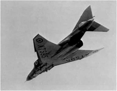
The Phantom (RAF version), showing clearly the dog-tooth on the leading edge; the outer wings have 12° dihedral; there are blown leading and trailing edge flaps; the slab tail has 15° anhedral and a fixed slot; the rudder is inter-connected with the ailerons at low speeds.

Подпись: Fig 11.24

Other devices to prevent or delay separation

Leading edge flap, double-slotted trailing edge flap and air brake

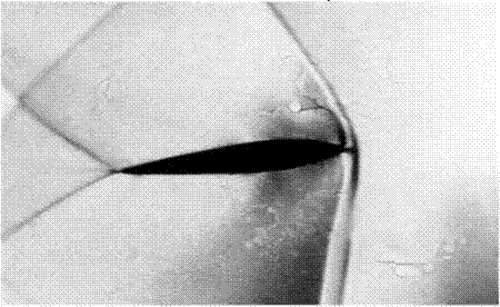
Fig 11F Shock waves

Shock waves from an aerofoil at incidence to the flow. Note the stronger leading edge shock on the underside. The wave in the top left-hand corner is a reflection from the wind-tunnel wall.

remains good, and the flow around it changes little between subsonic and tran­sonic speeds.

Can you answer these?

1. Is the speed at which sound travels in water higher or lower than that at which it travels in air?

2. Does the speed of sound change with height – if so, why?

3. At what part of a wing does a shock wave first form?

4. What is the buffet boundary of an aircraft?

5. What is a Mach Number, a critical Mach Number, and a machmeter?

6. How does the appearance of a shock wave on a wing affect the pressure distribution over the wing?

For solutions see Appendix 5.

Vortex generators

Many devices are used by the designer to control the separation or breakaway of the airflow from the surface of the wing – all these devices, in one way or another, over one part of the wing or another, have this in common, that they are intended to prevent or delay this breakaway. How? Well, that depends to some extent on the device, and we will consider vortex generators first (Fig. 11D).

The fundamental reason for the breakaway is that the boundary layer becomes sluggish over the rear part of the wing section, flowing as it is against the pressure gradient. The formation of a shock wave makes matters worse; the speed in the boundary layer is still subsonic which means that pressure can be transmitted up stream, causing the boundary layer to thicken and, if the pressure rise is too steep, to break away from the surface. Now vortex gener­ators are small plates or wedges, projecting an inch or so from the top surface of the wing, i. e. three or four times the thickness of the boundary layer. Their purpose is to put new life into a sluggish boundary layer; this they do by shed­ding small lively vortices which act as scavengers, making the boundary layer turbulent and causing it to mix with and acquire extra energy from the sur­rounding faster air, thus helping it to go farther along the surface before being

Vortex generators

Fig 11.20 Area rule – effect of wings and tail on plan view of fuselage slowed up and separating from the surface. In this way the small drag which they create is far more than compensated by the considerable boundary layer drag which they save, and in fact they may also weaken the shock waves and so reduce shock drag also; and the vorticity which they generate can actually serve to prevent buffeting of the aircraft as a whole – a clever idea indeed, and so simple. The net effect is very much the same as blowing or sucking the boundary layer, but the device is so much lighter in weight and simpler. The greater the value of the thickness/chord ratio the more necessary does some such device become.

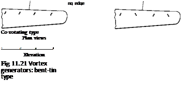
There are various types of vortex generator; Fig. 11.21 illustrates the bent – tin type, which may be co-rotating or contra-rotating. The plates are inclined at about 15° to the airflow, and on a wing are usually situated on the upper surface fairly near the leading edge.

Area rule

We should by now realise that if the drag is to be kept to a minimum at tran­sonic speeds, bodies must be slim and smooth, and have ‘clean lines’. What is the significance of clean lines? Well, it is often said to be in the eye of the beholder, what looks right is right – yes, but it depends on who looks at it; and a little calculation, a little rule, formula, or whatever it may be will often aid our eyes in designing the best shapes for definite purposes. The area rule (Fig. 11C) is simply one of these rules, and put in its simplest form it means that the area of cross-section should increase gradually to a maximum, then decrease gradu­ally; in this sense a streamline shape obeys the area rule, though for transonic speeds, and indeed for high subsonic speeds, the maximum cross-sectional area should be about half-way, rather than one-third of the way back, this giving a more gradual increase of cross-sectional area with an equally gradual decrease. The body in Fig. 11.19 (overleaf) obeys the area rule – but it hasn’t got any wings. If we add a projection to a body, such as the wings to a fuselage, we shall get a sudden jump in the cross-sectional area – and that means that the area rule is not being obeyed. What then can we do? – the answer is that we must decrease the cross-sectional area of the fuselage as we add the cross-sectional area of the wings in such a way that the total cross-sectional area of the aeroplane increases gradually. Similarly behind the point of maximum cross-sectional area it is the total cross-sectional area that must be gradually decreased.

Area rule

Fig 11C Transonic area rule

The transonic British Aerospace Buccaneer which finally saw action in the Gulf War shortly before retirement. The bulge in the rear fuselage is for purposes of area rule.

Rear of fuselage is cut off for

Area rule

Fig 11.19 Area rule – plan view of fuselage without wings or tail

It will be realised that the application of this rule gives a waist to the fuse­lage where wings or other parts such as the tail plane are attached (Figs 11.19 and 11.20). It will be realised, too, that sweepback – in addition to its other advantages – is to some extent an area rule in itself so far as the wings are con­cerned, the cross-sectional area being added gradually, and so the waisting of the fuselage will be less marked with swept-back wings than with straight wings.