Category Modeling and Simulation of Aerospace Vehicle Dynamics

Unsteady Reference Flight

Return to Eqs. (7.18) and (7.19), the general perturbation equations, and keep the unsteady term sflDIRDpDrlBrrI. They model the perturbations of aerospace vehicles in maneuvering flight. Unsteady means that the reference flight is rotating, like the pull-up maneuver of an aircraft, the circular intercept path of an air-to-air missile, or the pushdown trajectory of a cruise missile during terminal attack. If the parameters in the differential equations are functions of time, like the Mach dependence of aerodynamic coefficients, I call these terms nonautonomous.

Because we concentrate on nonspinning vehicles, the body frame is chosen as the dynamic frame, and we modify Eq. (7.18)

D’epb + sSlBIRBpBrplBr = efa + eft +(E – RBpBr)fgr (7.30)

and Eq. (7.19)

Dlelf + еПві RBpBrlBRr’ = єта + cm, (7.31)

To simplify these perturbation equations, second-order terms in є are neglected. Such terms will now be identified. First, the rotational time derivatives are trans­posed to frame Bp via the Euler transformation:

D1 spB = DBpspB + ПВрІєр’в

DlelBi = DBpslBJ + ГlBp, elBBl

then, Eq. (7.13) is used to replace ftBp!. Finally, substituting back into Eqs. (7.30) and (7.31) yields the second-order terms єПВІєрв and e£Ib’e:Ibr!. Neglecting these terms reduces Eqs. (7.30) and (7.31) to

DBpEp’R + RBpBrnRr, RBpBrEp’R + e£Ibi RBpBr pBr

= efa + ef, + (E – RBpBr)fgr (7.32) *

DRpeIbi + RBpBrnBrlRBpBrElBI + ESlBIRBpBrlBBr’ = Etna + єт, (7.33)

The second terms on the left-hand sides are the vestiges from the Euler transforma­tions. They couple the reference rotation £lBrI with the perturbations spB and e:Ibr .

We continue with the introduction of the linear velocity perturbation svB and the angular velocity perturbation єшВІ, using the definition of Eqs. (7.6) (mass does not change from the reference to the perturbed flight)

ep’B = e(mvlB) = emvg+mevg = meVg (7.34)

and Eq. (7.7)

ЄІВІ = Є(ІВШШ) = ЄІВШШ + IrEU>BI = ІдЄШВІ

We use the fact that the perturbation of the MOI tensor is also zero. This follows from the definition of the MOI perturbation Eq. (7.12), where the rotated MOI tensor IBrr, now coinciding with IRP, is subtracted from IBRp:

el = IBBpp – RBpBrIBrr RBpBr = 0

With the definition of Eq. (7.11) and replacing iBRr by IBBp, the angular momentum perturbations evolve with the definition of єшВІ [Eq. (7.9)] as follows:

Подпись: (7.35)eIbJ = 1ВрршВр1 – RBpBrl%uBrl = 1%{шВр1 – RBpBrcoBrI)

– lBpEU>BI

— 1Врєш

Substituting Eqs. (7.34) and (7.35) into Eqs. (7.32) and (7.33) produces the per­turbation equations of unsteady flight in tensor form suitable for applications

mDBpevB + mRBpB’TLBrIRBpBrsvIB + meSlBl RBpBrv’Br

= efa + ef, + (E – RBpBr)fgr (7.36)

I Bp DBpEOJBI + RBpBrnBrlRBpBrIBp)EOjm + ESlBIRBpBrIBBrru>Brl

= E, ma + Em, (7.37)

The perturbation variables are the linear velocity evb and angular velocity ешВІ. The perturbation attitude angles в, ф are contained in the small rotation tensor RBpBr. Look at the terms on the left-hand sides of both equations, going from left to right: first, the time derivative wrt the perturbed body frame in anticipation of using perturbed body coordinates; second, the unsteady term caused by the rotating reference flight. The last terms of the left sides have a different purpose in each equation. In the first equation it is the coupling term with the angular momentum equation through ешві. In the second equation this term makes an unsteady contribution of шВгІ, similar to the preceding term.

To use the equations in numerical calculations, we express them in body co­ordinates associated with the perturbed frame Bp. The rotation tensor [RBPBr]BP disappears, as we transform the reference variables [vBr]Bp, a>RrlRp, and |lB’rHp to the reference body axes ]Br. With the gravitational term expressed in inertial axes according to Eq. (7.25), Eqs. (7.36) and (7.37) become

Подпись:

Unsteady Reference Flight

BP + ,«[««’■’] ЙГК]ЙР + т[ЕиВІ}ВрШВг = [sfalBp + [ef,]Bp + ([T]BpBr – [EmfrlUgrV (7.38)

Подпись: (7.39)[sma]Bp + [Em,]Bp

We succeeded in expressing all perturbation and references variables in perturbed and reference coordinates, respectively. The transformation matrix [T]BpBr consists of the attitude perturbations в, ф, whereas [T]BrI establishes the coordinates of the gravitational force in reference body axes. Frequently, you will choose the Earth as inertial frame and the associated local-level coordinate system (see Sec. 3.2.2.7). Then, the gravitational force will take a particular simple form [/gr]L = m[0 0 g]. How can we apply these equations? Imagine an air-to-air engagement. The target aircraft pulls a high-g maneuver, and the missile goes for the kill in a circular trajectory. Both execute unsteady circular trajectories. Record the reference values of [vBr]Br, a)Rr,R’ and [T]BrI for the aircraft and the missile. To analyze the dynamics of either vehicle, insert these reference values into Eqs. (7.38) and (7.39) and provide the appropriate mass and aerodynamic and propulsive parameters.

Equations (7.38) and (7.39) are the starting point for the two examples of Sec. 7.5. But before these equations can be derived, we have to deal with the subject of aerodynamic modeling and linearization.

Steady Reference Flight

I define steady as the nonaccelerated and nonrotating flight and choose the body frame В as the dynamic frame. With шВгІ — 0 (nonrotating reference flight) and therefore lRll — 0, Eqs. (7.18) and (7.19) simplify to

D’eP’r + snBIRBpBrp>Br = Efa + e/, + (E – RBpBr)fgr (7.20)

DlslBJ — єта – I – smt (7.21)

To prepare for the use of the perturbed body coordinates ]Bp, we transform the rotational derivatives to the Bp frame. Let us start with Newton’s equation Eq. (7.20) and use the fact that шВгІ = 0:

D’sp’ = D^sp’g + SlBpIsplB = DBpsplB + ПВрВгєр’в

Substitute the rotational derivative and use the definition of the linear momentum Pb = mvB-

m(DBpevIB + ПВрВгву’в + еїіш RRpRrv’Rr) = efa + eft + (E – RBpBr)fgr (7.22)

Euler’s equation is obtained by a similar transformation

О’еіЦ = DRpeIri + ГBplElBi = DBpslBJ + ГlBpBrElBJ

and substituting it into Eq. (7.21):

DBpElBB! + ГlBpBrElBJ = Em a + Em, (7.23)

Modifying the perturbation e:Irr [Eq. (7.11)] by the definition of the angular mo­mentum Eq. (7.7), and with шВгІ = 0, we obtain

_jB/ /BpI nBpBrjBrl jBp. .BpI nBpBr jBr. .Brl j^P, ,BpBr

SlB tBp – R и lBr = iBpU – K ІВгШ – 1ВрШ

and simplify Eq. (7.23) (with DBpIBR = 0):

l%DBpujBpBr + ПВрВгІврршВрВг — Em a + em, (7.24)

Equations (7.22) and (7.24) are the perturbation equations of steady flight in their invariant form. We select the perturbed body coordinates ]Rp for the component formulation. First we deal with the gravitational term

{[E]Bp – [RBpBr]Bp)[fgr]Bp = ([E]Bp – [RBpBr]Bp)[T]BpI[fgry

Подпись:= ([T]BpBr ~ [E])[T]Br,[fgr]>

then we express the linear momentum equations in ]Bp coordinates

Steady Reference FlightSteady Reference Flightd єуівЛВр
At

= Wa]Bp + W,}Bp + ([T]BpBr – [E])[T]BrI[fgr}! (7.26) and the angular momentum equation

Г As&pBr~BP

[lZ +№ВрВг]Вр[1вр]P[a>BpBr]Bp = [sma]Bp + [smt]Bp (7.27)

Steady Reference Flight

These equations are nonlinear differential equations in the perturbation variables [ev1b]Bp and [aBpBr]Bp. Eq. (7.26) is coupled with Eq. (7.27) through [aBpBr]Bp. In addition, the underlined term of Eq. (7.26) also couples the angular veloc­ity perturbations via the reference velocity. With small perturbation assumptions and therefore neglecting terms of second order, we can linearize the left-hand sides:

Подпись: (7.28)Подпись:= WaBp + w, fp + (iTiBpBr – m)mBr,.uY

[-J BpBr-Bp

KTP =[ema]Bp + [emt]Bp

As you see, the translational equation (7.28) is still coupled with the rotational equa­tion (7.29) through the angular velocity perturbations [a>BpBr]Bp. Equation (7.29) would be uncoupled from Eq. (7.28) were it not for the aerodynamic moment [єта]Вр, which is a function of the linear velocity. Both equations are still nonlin­ear differential equations through their aerodynamic functions.

The perturbation equations for steady flight are the workhorse for linear stabil­ity analysis. They apply equally to aircraft and missiles and have been used as far back as Lanchester, that great British aerodynamicist who introduced the stability derivative. A more intriguing challenge is the modeling of perturbations for un­steady flight. Much of our hard-earned tools will have to be put to use. With them we can study such exotic problems as the stability of cruise missiles in pitch-over dive and the dynamics of agile missile intercepts.

Linear and Angular Momentum Equations

We use the component perturbation method to formulate the general perturbation equations of atmospheric flight. In this section I derive the perturbed linear and angular momentum equations and follow up with a detailed discussion of the aerodynamic force expansion in the next section.

The linear momentum of the body В with mass m relative to an inertial frame I is given by Eq. (5.3):

Pb = mvB (7.6)

where Vg is the linear velocity of the c. m. В relative to frame I. The angular momentum Ig1 of body В relative to frame / and referred to the c. m. В is defined by the MOI tensor Ig of body В referred to the c. m. В and the angular velocity vector со81:

jBI ___ jB..BI /"7 -74

lB = IgO) (7.7)

Using Eq. (7.2), the following є perturbations of the state vectors are generated:

svb= vbp – RvBr (7-8)

єшв1 = шВрІ – RojBrI (7.9)

and for the linear and angular momenta

£Pb = Pbp ~ яРвг (7-Ю)

Q]BI ___ jBpI DjBrI

ЄІв ~lBP Khr

Generalizing these equations for second-order tensors yields for the MOI tensor

e1bb = 1% – RlfrR (7.12)

and the skew-symmetric form of the angular velocity vector

sflDI = flDpI – RflDr, R (7.13)

Newton’s and Euler’s equation are replicated from Eq. (6.38):

DIpIB=f = fa+f,+fg (7.14)

D’lBJ = m = ma + m, (7.15)

where / represents the forces and m the moments relative to the c. m. B. The subscripts a, t, and g refer to aerodynamics, propulsion, and gravity, respectively. Both equations are valid for the reference and perturbed flights.

To derive the linear momentum equations, let Eq. (7.14) describe the perturbed flight

D/PBp = fap + ftp + fgp

and introduce the є perturbations for each term

D’spl + D‘ (,Rpl) = efa + Rfar + ef, + Rftr + efg + Rfgr (7.16)

Let us modify the second term on the left side by applying the generalized Euler theorem, the chain rule, and the definition of the angular velocity vector Eq. (4.47). With Eq. (7.13) we obtain

D1 є pi + EflDIRp‘Br + RD’plBr

— Rfar + Rftr + Rfgr + efa + sft + £fg (7.17)

The underlined terms are actually Eq. (7.14) applied to the reference flight and rotated through R. They are satisfied identically. The last term can be rewritten using the fact that the gravitational force is the same for the perturbed and reference flights fgp = fgr:

sfg = fgp ~ Rfgr = (E – R)fgr

The perturbation equation of the angular momentum is derived in the same way. Both equations are summarized as follows:

D’spl + e^’R^pI = Bfa + ef, +(E~ RDpDr)fgr (7.18)

D1 eIbJ + £nDIRDpDrlBBr‘ = Etna + Etnt (7.19)

These are the general perturbation equations of atmospheric flight mechanics. No small perturbation assumptions have been made as yet. They are expressed in an invariant form, i. e., they hold for all coordinate systems. Two types of vari­ables appear. The linear and angular momenta of the reference flight p’Br and lRfj. are known as functions of time; and the component perturbations are marked by a preceding e. The latter expressions єр! в and eIbJ represent the unknowns. The
aerodynamic forces and moments will be discussed in Sec. 7.3. Evaluating the per – turbational thrust and gravity forces is straightforward and will not be addressed.

The first terms on the left-hand sides of Eqs. (7.18) and (7.19) are the time rate of change of linear and angular momenta, whereas the second terms account for unsteady reference flights. Both equations are coupled nonlinear differential equations. To help you gain insight into the structure of the perturbation equations, I will derive two special cases: the all-important perturbations about a steady reference flight and the equations for turning reference flight.

Perturbation Techniques

The classical perturbation technique, as outlined by Etkin,1 proceeds as follows. First, an axis system is defined in relationship to physical quantities, such as the principal body axes or the relative wind velocity. The components of the state parallel to these axes are then identified. A particular steady flight regime is selected

with certain values for the reference components, e. g.,x, i, xr2, xr3, and a perturbed flight with xpi, xp2, Xp-}. The scalar differences

Ax,- = x Pi — xri i — 1,2,3

are the perturbation variables. Because the perturbations are generated by a scalar subtraction, this technique is also called the scalar perturbation method (see Ref. 2). The disadvantage of this technique lies in the fact that all of the formu­lations are tied to one particular coordinate system. A change to other coordinate systems is very difficult to accomplish.

In theoretical work vectors are preferred over components, and perturbations are defined as the vectorial differences between the reference and perturbed vectors. No allusion is made to a particular coordinate system. Because this technique considers the total state variable rather than its components, it is called the total perturbation method. Denoting the state vectors during the reference and perturbed flights as xr and xp, respectively, the total perturbation is defined as

Sx = xp — xr

The total perturbations have the advantage over the scalar perturbations that they hold for any coordinate system. In applications, however, numerical calculations require that vectors be expressed by their components, referred to a particular coordinate system. For instance, the MOI is given in body axes; vehicle acceleration and angular velocity are measured by accelerometers and rate gyros, mounted parallel to the body axes; wind-tunnel measurements are recorded in component form; and the whole framework of aerodynamics is based on force and moment components rather than total values.

To express the total perturbations in components, a transformation matrix must be introduced. In our notation the components of the Sx perturbation, relative to any coordinate system, say ]°, become

[&xfp = [XpfP – [T]DpDr[xr]Dr (7.1)

The subscripts r and p indicate reference and perturbed flights, respectively; [xr]Dr and [xp]Dp are the components as measured during reference and perturbed flights; and [TfPDr is the transformation matrix of the coordinate system associated with the perturbed frame Dp relative to the coordinate system associated with the ref­erence frame Dr.

Every numerical evaluation of equations based on the total perturbation method includes the transformation matrix [T]DpDr. Consequently, the transformation an­gles and their trigonometric functions enter the calculations, increasing the com­plexity of the equations considerably.

Wouldn’t you rather work with a perturbation methodology that combines the general invariance of the total perturbation method for theoretical investigations with the simple component presentation of the scalar perturbation method? We can formulate such a procedure by introducing the rotation tensor RDpDr6l the Dp frame wrt the Dr frame in the following form:

Подпись:sx — xp — RUpUrxr

The ex perturbation is obtained by first rotating the reference vector xr through RDpDr ancj ^еп subtracting it from the perturbed vector xp. It satisfies our first requirement of invariancy. To show that it reduces to a simple component form, we impose the ]Dp coordinate system and transform the reference vector to the ]Dr system:

[ex]Dp = [.xpfp – [RDpDr]Dp[xr]Dp

= [xpfp – [RDpDr]Up[T]DpDr[xr]Dr = [xpfp – [xrfr

The last equation follows from Eq. (4.6). Note that the transformation matrix of Eq. (7.1) is absent. Because this technique emphasizes the component form of a vector, Eq. (7.2) is referred to as the component perturbation method or alternately as the є perturbations.

When you work with the component perturbation method, the choice of the RDpDr tensor and thus the selection of the frame D is most important. As a general guideline, choose D so that the є perturbation remains small throughout the flight. Especially in atmospheric flight, the selection of D is determined by the require­ment of representing the aerodynamic forces as a function of small perturbations. Then a Taylor-series expansion is possible, and the difficult task of expressing the aerodynamic forces in simple analytical form can be achieved. I propose the des­ignation dynamic frame for D because the dynamic equations of flight mechanics are solved in a coordinate system associated with frame D.

Let us discuss some examples. The dynamic frame of an aircraft is either the body frame В or the stability frame S. In both cases, for small disturbances, the rotation tensors are close to the unit tensor, expressing the fact that the frame Dp has been rotated by small angles from Dr. As will be outlined in more detail in Sec. 7.3, the dynamic frame plays also an important role in the aerodynamic force and moment expansions.

In missile dynamics the situation is similar except that the aeroballistic frame replaces the stability frame. However, for a spinning missile the body frame can­not serve as a dynamic frame because the perturbations of the aerodynamic roll angle can be large. To keep the perturbations small between the wind and dynamic frames, the nonrolling body frame is chosen as dynamic frame. The motions be­tween the body frame and the dynamic frame thus are not explicitly included in the aerodynamic expansion, but rather the derivatives depend on them implicitly. To simplify the notation, I will use the abbreviated form R for RDpDr whenever appropriate. ,

Perturbation techniques enable us to expand the aerodynamic forces in terms ot small variables about the reference flight. Suppose /(x) is the aerodynamic force vector with x representing a state vector. The force during the perturbed flight f(xp) is expressed in view of Eq. (7.2) by

f(xp) — /(ex + Rxr)

Expanding about the reference flight (ex = 0) yields

where 3 //Эх is the Jacobian matrix. The Principle of Material Indifference, famil­iar to us from Sec. 2.1.3, states (see Ref. 3) that the physical process, generating fluid dynamic forces, is independent of spatial attitude. In other words, if xr is rotated through R, the process of functional dependence remains the same. The only difference is that the force has also been rotated through R, i. e.,

Rf{xr) = f{Rxr)

Making use of this fact, Eq. (7.3) becomes

f(Xp) = Rf(Xr) + ЄХ + ■■■ (7.4)

and / behaves like the є perturbations, introduced by Eq. (7.2)

fp = Rfr + sf (7.5)

The component or є perturbations satisfies both requirements of invariancy for theoretical derivations and simple component form for practical calculations. They are a generalization of the classical scalar perturbation method and are particularly well suited to formulate perturbations in a form invariant under time-dependent coordinate transformations.

Perturbation Equations

The last chapter completed the toolbox for modeling aerospace vehicle dynam­ics. You are now well acquainted with Newton’s and Euler’s laws as modeling tools for the equations of motion. In Chapters 8-10 we shall put them to work, simu­lating the dynamics of aircraft, hypersonic vehicles, missiles, and even Magnus rotors. Before pursuing that ambitious goal, I will address another important sub­ject of modeling and simulation that deals with the linearization of the equations of motions.

Why should we, living in the computer age, still concern ourselves with the simplification of the dynamic equations? I can think of three reasons, and you may be able to add some more.

1) Stability investigations are an important part of any vehicle design. They require the linearization of the equations of motion in order to take advantage of linear stability criteria.

2) Control engineers will always need linearized representations of the plant, be they transfer functions or in state variable form.

3) For a basic understanding of the vehicle dynamics, the eigenvalues of the linear equations serve to indicate frequency and damping.

These simplifications are accomplished with perturbation techniques. There is the classical small perturbation method, developed to solve specific problems in atmospheric flight mechanics. It employs scalar perturbations and relates them, for each type of flight vehicle, to a special coordinate system. Instead of deriving the general perturbation equations first, restrictive assumptions are made, and, consequently, the perturbation equations are limited to steady flight regimes.

The objective of this chapter is to introduce the general perturbation equations of atmospheric flight mechanics that are valid even for unsteady flight regimes. To keep the derivation simple, the flight vehicles are assumed rigid bodies.

I will discuss three techniques, the scalar, total, and component perturbations and use the latter to derive the general perturbation equations of aerospace vehicles. They apply to any type of vehicle from aircraft to spinning missiles. Then I will address the expansion of the aerodynamic forces and moments into Taylor series. Taken together, they deliver the linear dynamic equations. Examples of pitch and roll linear state equations demonstrate practical applications. I will also venture into the realm of unsteady flight with nonlinear effects to challenge your imagination.

Integrals of Motion

Force-free motions of spinning rigid bodies have occupied the interest of re­searchers for centuries, with the Earth as their primary object of scrutiny. Yes, the Earth nutates and precesses, although at such miniscule amounts that our daily lives are unaffected. Astrophysicists, however, earn their living by analyzing and
predicting these phenomena. The Frenchman Poinsot (1834) is particularly well known for his painstakingly geometrical description of the general motions of spinning bodies.

Modem technology has added other applications. Although gyros and spinning rockets are subject to moments and disturbances, much physical insight can be gained by studying their behavior in a force-free environment. Two integrals govern these motions. The angular momentum is constant in the absence of external moments, and the kinetic rotational energy is constant without work being applied to the body.

6.4.3.1 Angular momentum integral. In the absence of external moments, Euler’s law states that the inertial time rate of change of the angular momentum of a body В is zero:

D’lBjj = 0

If integrated in inertial coordinates, we arrive at the first integral of motions

[ig1]1 = [const]7 (6.66)

Note that we had to choose a coordinate system to carry out the integration. Had we picked the body coordinates, the integral of motion would be more complicated:

[lBI]B = – j[QBI]B[lf]Bdt + [ConSt]B

Equation (6.66) is also called the theorem of conservation of angular momentum. In the absence of external stimuli, the angular momentum remains constant and fixed wrt the inertial frame.

6.4.3.2 Energy integral. Without external moments no work is done on the spinning body, and therefore its kinetic energy remains constant, as confirmed by the energy theorem Eq. (6.64). Thus we conclude from Eq. (6.62), disregarding linear kinetic energy and substituting the angular momentum lBB = ІвшВІ, that the energy integral is constant:

2 TBI = іoBIlBBu>BI = QBIlBl = const (6.67)

Because we are dealing with a scalar product, Eq. (6.67) can be evaluated in any allowable coordinate system. Expressing it in body coordinates, which also serve as principal axes, we receive the energy ellipsoid

О

0

0 _

~0>“

[® 1 ®2 ®з]

о

о

0)2

о

о

w4

— /]«]+ І2СО 2 + /з®з = 2 TB!

and normalized

Подпись: (6.68)Подпись: = 1„ .2 ,.2 2

(О і ^3

2TBI/h + 2 TBl/I2 + 2TBl/I3

The energy ellipsoid is the locus of the endpoints of those vectors шві that belong to an energy level TBI. The three semi-axes are

a = y/2TBI/I, b = J2TBI/I2, c = j2TBI/h

Comparison with the MOI ellipsoid Eq. (6.13) establishes the fact that both ellip­soids are similar, i. e., their principal axes are parallel and scaled by the constant factor V2 TBI.

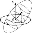
6.4.3.3 Poinsot motions. The two integrals of motion can be used to solve for the movements of spinning force-free bodies. Without the need for calculations, Poinsot has devised a geometrical method that visualizes the motions. For a detailed discussion you should consult Goldstein.2 I will just provide the essentials here and use Fig. 6.18 to explain the geometry.

1) Equation (6.67), with n — lB1 /lBI, defines a plane, whose normal form is шВІп — 2TBI/lg’ = const and which always contains the endpoint of шВІ.

2) Equation (6.66) fixes Ig1 in inertial space. The plane, defined by Eq. (6.67), is fixed in inertial space as well, and is called the invariable plane.

3) Equation (6.68), the energy ellipsoid, is the locus of all endpoints of шВІ.

4) The general motion of a force-free gyro, rotating about a fixed point B, is described by the rolling of the energy ellipsoid on the invariable plane.

Example 6.14 Impulse Control

Problem. A spin-stabilized missile with spin rate o>o and МОЇ I receives an impulsive torque /ив At from its reaction control jet. What is the new direction of the missile and what is the roll rate ф and nutation rate (/?

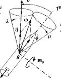
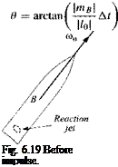
Solution. Figure 6.19 shows the missile before the impulse is applied. Its spin rate u>o and angular momentum lо are still aligned with the body axis IR. Now the reaction jet fires, and the impulsive torque introduces a nutation of the B axis of the missile (see Fig. 6.20). The new attitude of the missile is centered around the angular momentum vector l, displaced from its original position lо according to Eq.(6.5%) Ъу Al = mBAt. Therefore,

Подпись: (6.69)

Integrals of Motion

l = I0 + Ai = h + mB At

Integrals of Motion

The angle between Z0 and l is the change in the mean attitude of the centerline of the missile. It is the nutation angle в, calculated from Eq. (6.59) as

(In an actual application the nutation is reduced to zero by aerodynamic damping). The motion of the missile can be visualized by the body and space cones of Fig. 6.20. The body cone is centered on the Is axis, and the space cone contains the angular momentum vector, which is fixed in space. As the body cone rolls on the space cone, the missile traces its path. The angular velocity vector u> consists of two components, the roll rate of the missile ф and the nutation rate І]. They are calculated from the vector triangle, consisting of the absolute values p, ф, and f] the half-cone angles X and p.

First, we determine X, the angle between the angular momentum and angular velocity vectors. The angular momentum is given by Eq. (6.69) and the angular

Подпись: вПодпись: body cone Подпись: NПодпись: 2BПодпись: Fig. 6.20 After impulse.Integrals of Motionspace

cone


velocity vector by ш = I /. The scalar product yields the desired relationship:

Подпись: ШІA = arccos ■

The half-angle of the body cone is /г = 9 — X. From the law of sines, we can now calculate the roll rate

sin A __ _

Подпись:Ф = ~r~,—– —cu (6.70)

and the nutation rate

Подпись: (6.71)sin(7T — 9)

The roll rate ф increases with the widening of the space cone, and the nutation rate fj gets larger with the increase of the body cone.

This short excursion into gyrodynamics should give you an appreciation for the “strange” behavior of spinning objects. Their main modes are nutation and precession. Nutation is a fast circular motion of the body axis, whereas precession is a slower movement of the angular velocity vector. I introduced a new term, the kinetic energy of a rigid body TBR. It is a scalar that depends on the body В and an arbitrary reference frame R, consisting of rotational and translational kinetic energy. Flywheels are a good example for storing large amounts of rotational energy. Particularly simple to explain are the dynamics of force-free gyros. Two integrals of motion render Poinsot’s graphical representation of the energy ellipsoid rolling on the invariable plane.

6.5 Summary

This chapter is dominated by Euler’s law. We adopted the viewpoint that it is a ba­sic principle which governs the attitude dynamics quite separately from Newton’s law, although we recognize their kinship. For its formulation three new entities are needed. The moment of inertia is a second-order tensor, real and symmetric, can be diagonalized, and is represented geometrically by the inertia ellipsoid. The angular momentum vector derives from the linear momentum by the multiplication with a moment arm. For aerospace applications, however, it is more likely expressed as the product of the MOI tensor with the angular velocity vector. The externally applied moment or torque is the stimulus for the body dynamics. These are mostly aerodynamic and propulsive moments. Details will be discussed in Part 2.

The modeling techniques for flight dynamics are now completely assembled. You should be able to model the geometry of engagements, express vectors and ten­sors in a variety of coordinate systems, calculate linear and angular velocities, and derive the translational and rotational equations of motions of aerospace vehicles. I have consistently formulated first the invariant equations, and then expressed them in coordinate systems for computer implementation. We saw no need to deviate from the hypothesis that points and frames can model all entities which arise in flight mechanics. A consistent nomenclature sprang from this premise, enclosing all essential elements of a definition in sub – and superscripts.

You should be prepared now to face the cruel world of simulation, be it in three-, five – or six-DoF fidelity. In Part 2 I give you a running start with detailed examples and code descriptions that are available on the CAD AC CD. Before you proceed, however, I invite you to study one other topic, particularly important for engineering applications: the formulation of perturbation equations. Do not despise the “small” approximations, despite the raw computer power on your desk. Perturbation equations give insight into the dynamics of aerospace vehicles and are essential in the design of control systems.

References

1 Truesdell, C., “Die Entwicklung des Drallsatzes,” Zeitschriftfiir Angewandte Mathematik und Mechanik, Vol. 44, No. 4/5, 1964, pp. 149-158.

2Goldstein, H., Classical Mechanics, Addison Wesley, Longman, Reading, MA, 1965, p. 5,6.

3Mises, R. v., “Anwendungen der Motorrechnung,” Zeitschrift fiir Angewandte Mathematik und Mechanik, Vol. 4, No. 3, 1924, pp. 209-211.

4Grubin, Carl, “On the Generalization of the Angular Momentum Equation,” Journal of Engineering Education, Vol. 51, No. 3, 1960, p. 237.

5Bracewell, R. N., and Garriott, О. K., “Rotation of Artificial Earth Satellites,” Nature Vol. 182, 20 Sept. 1958, pp. 760-762.

6Klein, E, and Sommerfeld, A., Ueber die Theorie des Kreisels, 4 Vols., Teubner, 1910-1922.

7Magnus, K., Kreisel, Theorie und Anwendungen, Springer-Verlag, Berlin, 1971.

8Wrigley, W., Hollister, W., and Denhard, W. G., Gyroscopic Theory, Design and Instrumentation, M. I.T. Press, Cambridge, MA, 1969.

9Draper, C. S., Wrigley, W., and Hovorka, J., Inertial Guidance, Pergamon, New York, 1960.

Problems

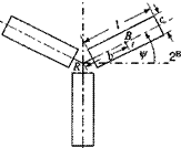
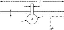
6.1 MOI of helicopter rotor. A three-bladed helicopter rotor revolves in the counterclockwise direction. Each blade has the same dimensions l = length, c — chord, and t = thickness. The mass center Вь of each blade к is displaced from

Integrals of Motion

1B!

the hub’s center R by b. Derive the MOI tensor of the three blades referred to R in helicopter coordinates [I^Bk]B. Assume constant density p of the blades.

6.2 Alternate formulation of axial MOI. The axial MOI /„ about unit vector n of MOI tensor IB is

In = nIBn

Integrals of Motion

or, with the definition of the MOI, summed over all particles і

Integrals of Motion

Show that it can also be expressed as

Integrals of Motion

where N — E — nn is the planar projection tensor of the plane with normal n [see Eq. (2.25)].

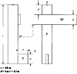
6.3 Mass properties of transport aircraft. For a six-DoF simulation of a transport aircraft, you need rough values for the mass mB and the MOI tensor [IB]B of the total body В referred to the common c. m. C and expressed in body axes ]fi.

(a) Formulate the equations of the individual MOIs [I$]B, [lp]R, Ip]R of wing, fuselage, and tail wrt their respective c. m. and express them in body axes. Afterward calculate their numerical values.

(b) Formulate the equation for the displacement vector L? cr]S of system c. m. C wrt the reference point R at the nose of the aircraft. Afterward calculate its numerical value.

(c) Formulate the displacement vectors swcH, I. v rc IR, І sjc1H for the subsystems c. m. wrt to C. Afterward calculate their numerical values.

(d) Now provide the equations of the vehicle’s total mass properties mB and

[/«?]*•

(e)

Integrals of Motion

Calculate the numerical values of the vehicle’s total mass properties mB and
Подпись: 2BIntegrals of Motion

Integrals of Motion

Density = 15 kg/tn3

6.4 Change of reference point. A helicopter rotor R has the angular momen­tum [lf]B wrt the Earth E, referred to the rotor’s c. m. R, and expressed in the helicopter’s body axes lfi. The helicopter flies over the spherical Earth at an alti­tude h with the velocity [uf ]fi = [їм 0 0]. What is the rotor’s angular momentum llRE]B wrt the center of Earth El

6.5 Total angular momentum of a helicopter. The airframe of a helicopter В with mass mB has three rotary devices affixed: the main rotor with mass mM and MOI /^; the turbine mr, lTT and the tail rotor mR, /{$. While the helicopter is hovering, you are to calculate the total angular momentum [l^1]8 of the helicopter wrt the inertial frame and referred to the common c. m. C in helicopter coordinates ]fi. The individual MOI’s and angular velocities are in air-frame coordinates H:

mB =

і

°

0

I М2

1

О О

^ °

1___

0

hi

f——-

О О

_ 0

0

1мъ_

_ 0

0

hi

hi

0

0

0

1r2

0

0

0

hi

ШМВ]В = [0 о [ЮТВ]В = [(0т 0 0], [coKBR = [0 wR 0]

Integrals of Motion

6.6 Force-free body parameters. A force-free body В spins around its c. m. В with [of’1]1 = [1 0 2] rad/s, having an MOI of [/f ]fi = [diag(3, 2, 2)] kgm2. What are its angular momentum [If7]7 and kinetic energy TB,1

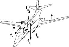
6.7 Forces and moments. А В1 aircraft is subject to several forces and mo­ments. The aerodynamic forces fa and ma are referred to reference point R, and the propulsive thrust of the right and left engines are / respectively. To make a right turn, the pilot generates with the ailerons a couple mc. What are the resultant force / and moment /яв wrt the aircraft mass center B1 Introduce the necessary displacement vectors to make the equations self-defining.

Integrals of Motion

6.8 Symmetric gyro. A symmetric gyro executes motions characterized by the condition that three vectors always are coplanar: the angular momentum lg, the angular velocity шВІ, and the unit vector b i of the symmetry axis .Use the following special components to verify this statement:

~h

0

O’

~0~

0

h

0

, [ЬЛВ =

0

_0

0

h.

_1_

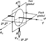
6.9 Free gyro. A two-axes gyro has two free gimbals. The inner gimbal sup­ports the spin axis, and the outer gimbal rotates freely in the bearings attached to the vehicle В. The gimbal pitch angle 6(, and yaw angle фс are indicated by their angular rate vectors 6 a and ф a ■

(a) Derive the relationship between the gimbal angles and Euler angles of the vehicle. Procedure: The spin axis s is parallel to the l5 axis and to the I’ axis (assuming ideal gyro). Express its body coordinates both in inertial ]7 and inner gimbal coordinates ]5:

(И® =)[Т]В7И7 = [T]BS[s]s

Integrals of Motion

where [T]BI contains the Euler angles and [TBS the gimbal angles. By comparing equal elements, the desired relationship is obtained.

(b) Derive the differential equations of the gimbal angles 6G and i/rc as functions of the body rates fwBIB = [p q r. Procedure: The angular velocity vector uisfi of the inner gimbal frame S wrt the body frame В is expressed in terms of the inertial body rates шт by the following steps. Take the rotational derivative of the spin axis s wrt the body frame В and transform it to the inner gimbal S and also to the inertial frame I:

(DBs =)Dss + SlSBs = D’s + flIBs

Because s is fixed in both the В and I frames, both derivatives are zero, and you get

nsfls = fl! Bs

For actual calculations it is most convenient to use the outer gimbal coordinates і о

[Й*ТМ° = [П“]0М0

and express the spin axis [.s]5 in inner gimbal coordinates and the body rates Q. ri’B in body coordinates then reversing the angular velocities

= [Т]ов[^в/]с,[Г]іі5[і]5

The result is

Oc — q COS l/fG + p sin fG
фа = r + (q sin i/fG — p cos ijrG) tan 9C

Both methods can be used to calculate the gimbal angles. What are their respective advantages and disadvantages?

Integrals of Motion

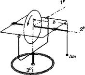
6.10 Gyro mass unbalance. The spin axis of a gimbaled gyro is subject to a mass unbalance Am, located at a distance b from the c. m. The resulting moment is constant in the inner gimbal (precession frame P). Determine the precession angular velocity rp if the spin velocity ф and the МОЇ I of the rotor are given.

Integrals of Motion

6.11 Change of reference point for kinetic energy. The kinetic energy Tm of a rigid body finds its simplest expression if its c. m. В is used [see Eq. (6.62)]. If an arbitrary point B of the body is introduced as reference point, show that the kinetic energy is calculated from the formula

where mBVgt flBRs bb, is the supplementary term required because B is not the c. m.

6.12 Bearing loads on turbine during pull-up. The Mirage jet fighter has a single turbine engine T located near the c. m. В of the aircraft B. As it pulls up, you are to calculate the forces and moments that the bearings have to support. The pull-up occurs in the vertical plane at a radius R and aircraft velocity Vg.

(a) Derive in invariant form the bearing forces counteracting centrifugal and gravity accelerations and the bearing torque opposing the gyroscopic moment.

(b)

Подпись: Bearings :

Express the bearing forces and moments in aircraft body coordinates while the Mirage is at the bottom of its pull-up. Besides R and [йд]в = [ V 0 0], the fol­lowing parameters are given for the turbine: mass mT MOI [IP]B = [diag(/i, h, /3)]; and angular velocity coTnB = [w 0 0]. You can assume that the two c. m. T and В coincide.

6.13 Control moment gyros of the Hubble telescope. The Hubble space tele­scope B0 is stabilized by three control moment gyros (CMG) Bt, B2, and B3. The

CMG mass centers have the same distance x from the center So and are equally spaced, starting with gyro #1 aligned with the 1B" axis of the telescope. The di­rections of the spin axes are shown in the accompanying figure. The following quantities are given: mass of telescope, m§ mass of one CMG, m; spin MOI of CMG, ls transverse MOI of CMG, /; angular rate of GMC wrt Bo, w; distance of CMG from Bo, x; MOI of telescope,

Подпись: 0 " 0 Іоз_ 7o 0 О /о 0 0

velocity of telescope wrt inertial frame, [v^J1 = [0 vq 0]; angular velocity of telescope wrt inertial frame, [ojBnI’ = [0 0 ®o]-

(a) For the cluster к — 0, 1,2,3, determine in tensor format the linear momen­tum p ^ B, the MOI / ^, the kinetic energy T1 й‘/, and angular momentum l 1.

(b) Express the four quantities in the telescope’s coordinates [R" using the TM

Integrals of Motion

COS l/f sin xjf 0 —sin іfr cos іft 0 0 0 1

Подпись: 1*0

6.14 Shuttle pitch equations during release of satellite. Derive the pitch atti­tude equations of the space shuttle Bo as it launches a satellite B. Assume that the release is parallel and in the opposite direction of the space shuttle’s 3 axis. The satellite’s displacement vector from the shuttle’s c. m Bo is [.v/;, l/f" = [—a 0 rj], where a is a positive constant and r}(t ) a known function of t. The mass of the manipulator’s arm can be neglected, and the satellite treated as a particle with mass mHi. The mass properties of the shuttle are mB" and [/^"]B" = [diag(/i, I2, h)]. Determine the differential equation of motion of the shuttle’s pitch angular velocity о>и‘]І B" = [0 q 0]. All external forces and moments can be neglected.

6.15 Missile pitch equations with swiveling motor. The attitude of a missile Bo is controlled by its swiveling rocket engine Bi with thrust 1D] = [T 0 0] and known swivel angle S(t). Neglecting all other forces and moments, determine the differential equation that governs the pitch angular velocity |ojB(|/ |B° = [0 ry 0] of the missile. The mass properties are given:

m B" • [ / a" ] B° = di ag( /!, /2, /3)

тв[ів’]В’ =diag(Jb J2, h)

Integrals of Motion

and assumed constant.

Solution 6.14

h(mB’ + mB°)

Solution 6.15

Подпись: q — 2 IL sin S(t)S(t)qПодпись: T —— L sin (5(f) mB'

Integrals of Motion

Подпись:

Подпись: where
Подпись: mBlmB° mBl + mB<>

+12 + L2 + 2IL cos 5(0 M

Kinetic Energy

You may have heard of the flywheel-car project. Instead of using battery power as alternate energy, the car is driven by the kinetic energy stored in a massive flywheel. You drive up to a filling station, plug the drive motor into an outlet, and spin up the wheel. Supposedly, the stored energy could propel you 50 miles around town. How do we calculate the stored energy of a flywheel and, in more general terms, the kinetic energy of a freely spinning body or cluster of bodies? How does the time rate of change of kinetic energy relate to the applied external moment? We begin by defining kinetic energy.

The kinetic energy of the particle with mass m,, translating with the velocity vf relative to the arbitrary reference frame R, is defined by

(6.60)

It is a scalar. Summing over the і particles of a body B, not necessarily rigid, establishes the kinetic energy of body В wrt reference frame R :

і і

This formulation is not very useful because it requires knowledge of every parti­cle’s velocity. By introducing the c. m. В of the body, we can derive a much more practical relationship.

Theorem: With the c. m. В of a rigid body В known, the kinetic energy TBR

of body В wrt to reference frame R can be calculated from its rotational and translational parts:

tbr _ і – BRjB, br і і я,-,/?,,/?

1 =2Ш 1 Вш +2W V Bv В (O. OZ)

The rotational kinetic energy is a quadratic form of the angular velocity u>BR of the body В wrt the reference frame R and the MOI tensor IB of body B, referred to its c. m. B. The translational kinetic energy is patterned after Eq. (6.61), using the scalar product of the linear velocity of the c. m. multiplied by the total mass mB of the body. Employing the c. m. of a body in calculating the kinetic energy is just a convenience yielding the most compact formula. Any other body point could be used. An additional term makes the adjustment and leads to the same numeri­cal result (see Problem 6.11). Because the numerical value is independent of the reference point, the nomenclature TBR refers only to the body and reference frames.

Proof: We start by expanding Eq. (6.61) and using the definition of the linear

velocity vf = DRsiR, with point R an element of frame R:

YlmiVfvR = Y^miDRSiRDRsiR

І І

Now we introduce the displacement vector triangle siR — siB + sBR with В the c. m. of В:

2 TBR = J2mi(DRSiB + DRsBR)(DRsiB + DRsBR)

Kinetic Energy

Because В is the c. m., the second and the third terms vanish. Why is this so? First, m, is constant, thus ]T, mjDRsiB = DR(miSiB). Second, summation and differentiation may be exchanged; therefore, DR(miSiB) = DR(^imiSiB) but 52; m;*iB = 0 is a null vector, and the rotational derivative of a null vector is zero. The last term, with the definition of the linear velocity = DRsBR, provides the

last term of Eq. (6.62). The first term needs some massaging to complete the proof. If В is rigid, DBSiB = 0, and

Y, miDRsiBDRsiB = ^т{0в$ІВ+ШЧТв){0В8ів + ftBRsiB)

І І

= 7>,nM»anB*sa,

І

After some manipulations and with the definition of the MOI tensor Eq. (6.1), we produce

uBR = G?*lW*

Moving the factor 2 to the right side confirms the first term of Eq. (6.62) and completes the proof.

Kinetic Energy Kinetic Energy Kinetic Energy Kinetic Energy Подпись: (6.63)

For a cluster of rigid bodies Bk, k = 1, 2, 3,…, we can superimpose the indi­vidual contributions of Eq. (6.62) and obtain the total rotational and translational kinetic energies

The proof follows from the additive properties of kinetic energy.

Example 6.13 Flywheel Car

Problem. A car with mass mBt stops to recharge its flywheel (mass mBl and MOI Ig22) to the maximum permissible angular velocity шВгК. If there were no losses, what would be the maximum speed the car could achieve?

Solution. Initially, all energy is stored in the flywheel. To reach maximum velocity, the rotational energy must be fully converted into translational energy. From Eq. (6.63)

imB’ +mB2)vRvRBx=G:B2RlBBluB2R

Let us introduce a coordinate system associated with reference frame R and the following components:

ЩЙ = [У 0 0], = 10 0 r], and [lBl]R = [diag(/i,/2,/3)]

After substitution we obtain the maximum speed of the car:

V tnB’ + гпВг

A fast spinning, large wheel in a light car will provide maximum speed.

Applying a torque to a body increases its rotational kinetic energy. The energy theorem describes the phenomena.

Theorem: The time rate of change of rotational kinetic energy of a rigid body

В wrt inertial frame I equals the scalar product of the body’s angular velocity шш and the applied moment mB referred to the c. m.

d TBI

—— = шВІтв (6.64)

d t

To maximize the increase of kinetic energy, the external moment must be applied parallel to the angular velocity. Interestingly enough, the increase does not depend on the MOI of the body, but the current angular velocity.

Proof: Let us assume that point В is fixed in the inertial frame I so that we can concentrate on the rotational kinetic energy. From Eq. (6.62)

2 TBI = шшІввшш

Take the time derivative of the scalar TBI, which is equivalent to the rotational derivative wrt any frame, and specifically the body frame. Then apply the chain rule

2^£- = 2 DBTBI = DboobiIhbojbi + wBlDB(lB<jjBI)

Recognize that the first term on the right equals the second term because 1) the term is a scalar and 2) the body В is rigid, which enables us to move /f (symmetric tensor) under the rotational derivative

DBo, BIlBBooB’ = ojBrIBBDBojBI = uBlDB(lBcoBI)

Thus, introducing the angular momentum fif — ІвшВ! we get

— = QB, DB (івШш) = G>BlDBlBJ (6.65)

dr

To replace the angular momentum term by the extemal moment, we substitute Euler’s equations, transformed to the body frame DBlBB + ГlB, lBJ = mB. Because the cross product with the same vectors vanishes, the proof is completed:

—— = шв,(тв — ГlBIlBB) = QB, mB QED

An important question in gyrodynamics is the conditions for which the kinetic energy remains constant. Besides two trivial cases (mB = 0 and шВІ = 0), the kinetic energy does not change if the external moment is applied normal to the spin axis. The energy theorem is useful for the study of gyroscopic responses and leads to one of the integrals of motions.

Precession and Nutation Modes

Euler’s law governs the dynamics of rotating bodies. In general, its differential equations are of sixth order, with three angular rates and three attitude angles as state variables. For bodies with constant spin rate, we are only interested in the rates and attitudes normal to the spin axis. They are governed by four first- order differential equations. If linearized by small perturbations, their characteristic equation has two conjugate complex pairs of roots, giving rise to two dynamic modes called precession and nutation.

6.4.1.1 Precession. Precession is the response of a gyroscope to a persis­tent external moment. Euler’s law reveals the nature of that response and enables us to derive a relationship between precession rate and external moment.

Precession and Nutation Modes Подпись: (6.56)

Consider a gyro В with angular momentum and subjected to the external moment mB. Euler’s law, Eq. (6.37), states that D1^1 = mB, i. e., the change of angular momentum is in the direction of the applied moment. Expressed in inertial coordinates and dropping the sub – and superscripts,

Precession and Nutation Modes

Integrated,

We evaluate the integral by dividing it into time increments At during which the moment can be considered constant:

[lit)]1 = Vito)]’ + ^[mk]‘ At

Подпись: к

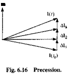
With fmic]1 At = [Д/fc]7 the last term becomes

[lit)]1 = Vito)]1 +

к

Figure 6.16 shows the integration process. The incremental angular momentum [AIk]1 is collinear with the instantaneous moment [mkY. Overall, the angular momentum vector [lit)}1 lines up with the moment vector. For a fast gyro for which the spin axis, the angular velocity vector, and the angular momentum vector
are close together, one can verbalize that the body axis tries to align itself with the moment vector.

This motion is called precession. It is the slower one of the dynamic modes of a gyro and poorly understood. You probably have been at a science museum where you could not resist taking a seat on a turntable and grabbing a spinning flywheel by its handles. As you try to bank the flywheel, your seat starts to rotate on the turntable. You get off and explain to your son that this demonstrates the weird behavior of a gyroscope. It would be better to tell him that you experienced a precession in response to the torque you applied to the flywheel and encourage him to ask his physics teacher to fill in the details.

To get a quantitative relationship between moment and precession rate, we go back to Eq. (6.37) and introduce the precession frame P. This frame stays with the precessing angular momentum vector. Shifting the rotational derivative to P produces

DplBJ + np, lBJ = mB

If the magnitude of is constant and because the vector lBB1 remains fixed in P, the rotational time derivative vanishes. The equation of the precession rate ГlPI is therefore

SlPIlBJ = mB (6.57)

This vector product establishes the right-handed rule of precession.

With Eq. (6.57) you can tell your son in advance how to apply the moment in order for the turntable to turn to the left. Turning to the left means the precession vector points up; and if the flywheel’s angular velocity vector points right, the cross product tells you to generate a forward-pointing moment vector. Grab the wheel, push the right handle down and the left one up. You will be become an instant hero.

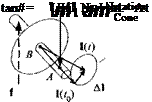
6.4.1.2 Nutation. Nutation is the response of a gyro to an impulse. Consider the free gyro in Fig. 6.17. We subject the gyro for a short time Дt to the moment mB = 2Sab/ and observe its reaction. According to Euler’s law [Eq. (6.56)], the change of angular momentum as a result of the impulsive moment is

Подпись:

Подпись: m

[Al]1 = [Щ)]1 – [l(t0)Y = [mB]! At

Precession and Nutation Modes Подпись: (6.59)

During At, the angular momentum vector jumps from [/(fo)]7 to [1(f)]1. The body axis, held back by the body’s inertia, is still in its original position and starts to respond by revolving around the new location of the angular momentum, tracing out the half cone angle в:

The greater the impulse and the smaller the initial angular momentum are, the greater this nutation cone becomes. Initially, the body axis yields in the direction of / but returns to its original position through the nutation cycle. On the average the body axis evades the impulsive force perpendicularly. For many successive impulses a fast gyro with small nutational motions appears to move normal to the applied force. In the limit precession can be thought of as a sequence of infinitesimally small nutations caused by a sequence of impulses.

Let us play with the top, whose dynamic Eq. (6.47) we derived earlier. It is spinning on the ground about the vertical. We shake it out of its complacency by imparting an impulsive moment with our whip. The top starts to wobble, but refuses to fall down. The higher its spin rate (angular momentum) the smaller the nutation angle and the greater its resistance to our onslaught. We witness the inherent stability of spinning objects to perturbations. Several technical applications make use of this feature. I already introduced the dual-spin spacecraft in Example 6.11, and in Chapter 10 I will derive the equations of motion for spinning missiles and Magnus rotors.

Gyrodynamics

Gyrodynamics is the study of spinning rigid bodies. It has many applications in modeling of aerospace vehicles. Just consider the gyroscopic devices in inertial navigation systems, gimbaled spin-stabilized sensors, dual-spin satellites, spin- stabilized projectiles and rockets, Magnus rotors, propellers, and turbojets.

The study of the Earth as a spinning object captured the interest of famous dynamicists like Poinsot, Klein, and others in the last centuries. During their time, it was the only practical application. Earth science and astronomy are benefiting to this day from their research.

Technical applications dominate today’s interest. Millions of dollars are spent either improving the performance of gyroscopes or lowering their cost for mass production. They are an integral part of any INS, affecting the accuracy of its nav­igation solution. Wherever a body spins in machinery, technical problems surface because of imperfections. Tires wobble, motor bearings fail, and Hubble gyro­scopes wear out and must be replaced.

For technical details, I refer you to the many excellent texts that are available. An early classic is the theoretical book by Klein and Sommerfeld.6 One of the best treatments, both theoretical and practical, is given by Magnus.7 Unfortunately, these books are written in German. The standard English reference is by Wrigley et al.8 An older account is given by C. S. Draper et al.9 Here, I will cover only some of the fundamental dynamic characteristics of gyroscopes. The mystery that surrounds the precession and nutation modes of fly wheels will be debunked. From the kinetic energy theorem we learn how a spinning body responds to external moments, and we will derive two integrals of motion for force-free bodies.

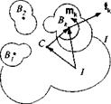
Clustered Bodies

If you are looking for a challenge, go no further than the dynamics of clustered spinning bodies. You can go back to Eq. (6.32) and sum over all particles, just as we did for a single body. Executing all of these steps would blow the chapter. Fortunately, we do not have to start from scratch, but take advantage of the angular momentum of clustered bodies, Eqs. (6.24) and (6.25). These equations serve two distinctively different situations. Equation (6.24) represents the more general case of moving bodies, whereas Eq. (6.25) assumes that all bodies c. m. are mutually fixed.

The second case is more important and easier to deal with. It applies to air vehicles with spinning machinery, like turbines, rotors, propellers, or flywheels. I will deal with it first. If your stamina has not been exhausted by then, you may continue with the more general case that applies to rotating and translating objects within the vehicle. Imagine a jeep being pushed backward in a cargo aircraft for parachute drop, or the movement of the space shuttle’s manipulator arm before release of a spinning satellite. I believe, however, both cases would be fun to explore.

Clustered Bodies

Fig. 6.15 Clustered bodies.

For both cases we begin with Euler’s second law Eq. (6.32) and sum over all particles of rigid body В

E D’lii = Ew’7

І І

which can be abbreviated by

D‘lf = m,

Now consider к rigid bodies Bk, к = 1, 2, 3,… with their external moments mk and forces fk (see Fig. 6.15). Summing over the entire cluster and shifting the reference point of the forces from their individual c. m. Bk to point I

m, = + j2SB*ifk

к к

yields

D‘ E^*7 = + E swfk

к к к

where we abbreviate the left side by D1 J2k ^ = В>Ії^Вк1

DllfBkI = E"1^ + E SBtifh (6-48)

к к

We zero in on the angular momentum of clustered bodies lfBkI using Eq. (6.24) with / as reference point

lTkI = E (іВвУкІ + mBkSвкІD1 sBti)

к

and introduce the common c. m. C of the cluster sbki — sbkc + sci into the last term

= E™SiSBtcDVc + Emg* SciD1Sq

к к к

+ SCi’S^mBkDIsBkc + y^jmBkSBkcDISci

к к

The last two terms vanish because C is the common c. m. Therefore

lfBkI = £/f‘wBt/ + J2mBtS^cD’sBtC + J2mBkSciD’Sa (6-49)

к к к

At this juncture the two cases require separate treatment. For the fixed case D/s, stc can be simplified because DcsBkC = 0. No such reduction is possible for moving bodies.

6.3.4.1 Mass centers are mutually fixed. Let us modify the second term on the right-hand side of Eq. (6.49) by transforming the rotational derivative to the C frame, which consists of the points Bk and the common c. m. C:

SBkc D1 s Звкс{0С s вкс + fiC/$stc)= ^m5tSstcfiC/$stc

к к к

Reversing the vector product and transposing the skew-symmetric displacement vector yields

Y^mBkSBkcQCISBkc = ^2mBkSBkCSBkcUCI

k k

We arrive at an intermediate result if we substitute this expression into Eq. (6.49) and recognize that the first two terms on the right-hand side of Eq. (6.49) are in effect Eq. (6.25):

/?Bi/ = lcBkl + £mB‘SaD/sCj

к

Substituting the angular momentum into Eq. (6.48) and introducing C as a refer­ence point at the right-hand side, we obtain

D‘llBtl + Dl (y^m^SaD^cA = £mB* + £ SBtcfk + $ci £ Л

к /к к к

Applying the chain rule to the second term and combining it with the last term produces a familiar equation

£mB‘Sc/D;DV/ = SaJ^fk = Saf

к к

which represents Newton’s equation applied to the common c. m. It is satisfied identically, and therefore Euler’s equation for bodies with mutually fixed mass centers consists of the remaining terms:

D’ll*1 =Y, m*+Y, SBkCfk

к к

For the final form, most useful for applications, we reintroduce Eq. (6.25):

£ Dl{tBB“Bkl) + £ D‘ (mB*SBtcSBkcua) = £«* + £ SBtCfk (6.50)

к к к к

Given the MOIs of the individual bodies Вk, their displacements, angular rates, and their external moments mk and forces f k, we can model their attitude equation. Let us apply it to an important example.

Example 6.11 Dual-Spin Spacecraft

Problem. A satellite, orbiting the Earth, is subject to perturbations that slowly change its attitude, unless thrusters correct the deviations. Such a control system is expensive to implement. Earlier in the space program, satellites would carry a rapidly spinning wheel that would maintain attitude just by the shear magnitude of its angular momentum.

The satellite consists of a cylindrical main body fi| and a cylindrical rotor B2, with their respective c. m. B and B2 and mass mB’ and mBl. The rotor re­volves about the third axis of the main body with the angular velocity coBlR’ ]Bl = [0 0 R], and the main body’s inertial angular velocity is [®B|/]S| = [p q r]. With the rotor placed at the common c. m., the points B,B2, and C coincide. Both MOIs are referenced to B and given in ]B| coordinates

Подпись:Подпись: В,lf+2 0 0

0 lf+1 0

о 0 lf+2

Derive the scalar differential equations of the satellite, free of external forces and moments.

Подпись: D1 Clustered Bodies

Solution. Because the centers of mass are mutually fixed, Euler’s law for clustered bodies [Eq. (6.50)] applies:

With loBi> = u>BlB< +tuBl/, point B2 — B, and abbreviating if +IB2 = IB+Bl
D‘(IBB+Вїшв’1 + ІВв]шВіВі) = 0

Подпись: DB'(IBB Подпись: Івв2шВ2В') +nB''(lB+B2u>B'‘ Clustered Bodies

Transform the rotational derivative to the frame of the main body B:

Clustered Bodies Clustered Bodies Подпись: BjB

The MOI of both the main body and the rotor (cylindrical symmetry) do not change wrt the main body; therefore, their rotational derivatives are zero, and we have arrived at the invariant formulation of the dual-spin spacecraft dynamics:

(6.51)

Подпись: [itBT Clustered Bodies Clustered Bodies

Let us use the main body’s coordinates ]Bl to express the equation

+[£lB>I]B'[l^]B'[coB2B’]Bl = [0]Bl

Substituting the components and multiplying the matrices yields the scalar differ­ential equations of a dual-spin spacecraft:

It 1+2P + (Iz+1 – IBl+V + IpRq = 0

IBl+2q – (lBwl – Ij’+2)pr – lB2Rp = 0 (6.52)

IB’+2r + IB2R= 0

The rotor’s angular momentum IBlR dominates with its high spin rate R the term (1B’+1 — IBw2)r and provides the stiffness for the satellite’s stabilization.

As a historical note, the first U. S. satellite Explorer I, launched in February of 1958, was spin stabilized but started to tumble after a few orbits. NASA overlooked the known fact that an object with internal energy dissipation is only stable if it is spinning about its major moment of inertia axis.

6.3.4.2 Mass centers are translating. Clustered bodies whose c. m. are translating relative to each other are more difficult to treat because the common c. m. is also shifting. We start with Eq. (6.49). Substituting Eq. (6.49) directly into Eq. (6.48) and introducing SBki = SBkc + Sci into the last term yields

X)Dl (!BBk“Bkl) + X mBk Sb‘c D’ D‘Sb>c + X щВк SaD’ D’Sci

к к к

= X] mBk + X sBtcfk + Sci X /*

к к к

where we expanded the second and third terms by the chain rule and took advantage of the vanishing vector product of like vectors. Embedded in this equation is Newton’s second law premultiplied by Sci-

Y, mB’SaDIDIsa = SciY, fk

к к

These two terms are satisfied identically. Voila, we have arrived at the Euler equa­tion of mutually translating bodies referred to the common c. m C:

X^(/^’) + X-^c^w = X"* + £W* (6.53)

к к к к

where the right-hand side sums up the moments applied to the common c. m. C:

mc = Хтв* + XSb‘c^

к к

The equation of motion consists of the MOIs IlBi of the individual parts and their inertial angular rates шВк’ plus an extra transfer term J2kmBk $BkcD! Drs вкс with a peculiar acceleration expression D1 D! sвкс■ This is the acceleration of the dis­placement vector s Btc as observed from inertial space. It does not include the inertial acceleration of the common c. m. For clarification we introduce the vector triangle Sekc =SBti -sci’-

D1 DfsBkc – D1 DlsBki – D1 D1 sci = aBk – a’c

As it turns out, it is the difference between the inertial accelerations of the individual c. m. Bk and the common c. m. C.

Example 6.12 Carrier Vehicle with Moving Appendage

A main vehicle B carries an appendage Bo, whose c. m. is moving wrt the carrier. Typical examples are the deployment of a satellite from the space shuttle, the swiveling nozzle of a rocket, or the tilting nacelle of the Osprey-type aircraft. In each case the common c. m. C is not fixed in the vehicle. In these applications it would be more convenient if the equations of motions were referred to a fixed point, usually the c. m. of the main body of the aircraft or missile. We can make that switch by transferring Euler’s equations to the c. m. B of the carrier vehicle.

Подпись: = mBi + mBl + SBJC/I + SB2cfi

We derive the attitude equations from Eq. (6.53), specialized for two bodies:

(6.54)

To replace C by B, we make use of two relationships, the moment arm balance and the displacement vector triangle,

mBlsBlc + mBlSB2c = 0

$ BiC — Sb2C = —SB2B

Clustered Bodies

Adding both equations, after the second one has been multiplied first by mBl and then by — mB’, yields the two relationships

Substituting these two displacement vectors into the third and fourth terms of Eq. (6.54), and into the last two terms, removes the dependency on the common c. m. C. After two pairs of terms are combined, we have produced Euler’s equation for a carrier vehicle B with moving appendage By.

Clustered BodiesD'(Ibbojb’1) + D

= mBl +mBl

Do you recognize the two rotary terms, the transfer term that contains the inertial acceleration of the displacement vector, and the external moments and forces? It may be puzzling what the state variables are. We can take two perspectives. For the applications that I mentioned, the translational and angular motions of the appendage are known as a function of time. Therefore, only шв” contributes three body rates as state variables. The differential equations are linear. If, however, the appendage has its own degrees of freedom, like the shifting cargo during aircraft maneuvers, шВг1 and Sb2b, become also state variables. Additional equations must be adjoined to furnish a complete set of differential equations, which will couple the motions of the two bodies. The whole set of equations are nonlinear and, as you can imagine, difficult to solve. To become familiar with the solution process, you should attack Problems 6.14 and 6.15.

6.3.4.3 Summary. With Euler’s law firmly in your grasp, you are fully equipped to model all aspects of aerospace vehicle dynamics. Never mind whether it is derived from Newton’s law or is a principle in its own right. What counts is that you are able to apply it correctly. From first principles I have built Euler’s equation for rigid bodies, either referring it to the c. m. or another fixed point. The free-flight attitude equation uses the c. m. to detach itself from the trajectory parameters, enabling the separation of the translational and attitude degrees of freedom. You should have no problem to derive the full six-DoF equations of motion of an airplane, missile, or spacecraft. The difficulty lies in the modeling of aerodynamics, propulsion, and supporting subsystems. We will pick up this challenge in Part 2.

I also introduced you to the dynamics of clustered bodies. In most aerospace applications their mass centers are fixed among themselves. Under those circum­stances the transfer term includes only one time differentiation. If the bodies are moving, second-order time derivatives of the displacement vectors appear. Partic­ularly important are spinning rotors, which introduce desired (momentum wheels) or undesired (propeller, turbines) gyroscopic effects. Because of their significance, we devote a separate section to their treatment.