Category Modeling and Simulation of Aerospace Vehicle Dynamics

Top

You may have played in your childhood with such a cone-shaped object and kept it spinning by lashing at it with the end of a whip. It made marvelous jumps, seemingly defying the law of gravity, as long as it spun fast enough. Now you realize that it is its angular momentum which stabilizes it.

Euler’s law governs the dynamics of the top. We derive its specialized form by considering the reference point R a point of body B, which implies that for any particle i, DBs— 0. Furthermore, R is also the reference point 7, thus Sr/ — sи — 0. Starting with the terms of Eq. (6.35), we modify them like before, except this time we cannot take advantage of the simplifications brought about by the c. m:

Term (1):

D’faSiRD’siR) = DI[miSu(DBsiI + 12B/s,,)]

/ І

= J2 D‘(mi Si, nBISu) = D1 (if u)BI)

І

Term (2):

YiDI(miSiaDIsRI)= 0

І

because sRi = s/j = 0.

Term (3):

J^D^miSaD’sR,) = £ D^S,^) = 0

І І

because v‘R = 0.

Term (4):

^D/(miSwD/s«)= 0

І

because Sw = S// = 0.

Term (5):

X>*/i) = £>,//,) = /я/

2 І

Term (6):

= «и/ = 0

І

because Srj = Sn = 0.

Only Terms (1) and (5) remain. Euler’s law for a body spinning about a fixed point / is

DI(lfa>BI)=mI (6.47)

Compare both formulations, Eqs. (6.36) and (6.47). They are distinguishable only by the reference points. In both cases, whether it is the c. m. or a body/inertial reference point, Euler’s law assumes the same simple form.

Example 6.10 Force-Free Top

A moment free symmetric body spins about its minor principal MOI axis and is supported at the bottom of its spin axis. Its MOI in body coordinates is

Подпись:h oo 0 /2 0 0 0 h

where the minor MOI is in the first direction and the two others are equal. The angular velocity of the top is a constant p0. Its attitude equations are derived from Eq. (6.47) by transforming the rotational derivative to the body frame В and expressing the terms in body coordinates }B

Подпись: вцв~dco‘

dt

With the angular velocity [a)BI]B = [po q r] the equations are in body coordinates

1

о

о

"о"

I

V

1

0

0 _

1

О

0 ^Г

1 _

Ро

"о~

о

о

<7

+

"5

0

1

о

о

о

q

0

1

о

о

г

1

1

о

О

I__

1

о

о

to4 1

г

0

and evaluated

hq – (h ~ h)por = 0

Ы + (h – h)poq = 0

These are two coupled linear differential equations with pitch rate q and yaw rate r as state variables. The terms (h — h)Por and (h — h)Poq model the gyroscopic coupling between the pitch and yaw axes. You should be able to verify the oscillatory solution

h ~ h

q = Ao sinfiwot), r = Aq cos (coot) with o)q =———— po

h

Ao depends on the initial conditions.

Euler’s law, like Newton’s second law, must be referred to an inertial frame and, for simplicity’s sake, should be referred to the vehicle’s c. m. Yet, just as in Sec. 5.3, we ask what are the correction terms if we change to a noninertial reference frame or an arbitrary body point.. Noninertial reference frame

Shifting the reference frame from inertial I to noninertial R, but maintaining the vehicles c. m. В as reference point, incurs two additional terms in Euler’s equation. We start with Eq. (6.37) and transform the rotational derivative to the R frame:

DRlBJ + nRIlBJ = mB

The first term is modified first by replacing the angular momentum with Eq. (6.23) and introducing the angular velocity relationship between the three frames В, R, and I: u>BI — ojbr + ojri,

Dr{Ibbojbr) + Dr{Ibbojri) + nmlBJ = mB

where І вшвк = lB/ is the angular momentum wrt the frame R. Now, the two correction terms are exposed on the right-hand side of Euler’s equation:

DRlBBR =mB-nRIlBB‘- Dr(I%u>ri) (6.42)

They consist of the precession term ilRIlBB [see Eq. (6.57)] and the reference rate term Dr(Ibu>ri). For instance, if we used Earth E instead of the J2000 as inertial frame

DElf = mB – iY’l’ll – De (lBu>FJ)

the two terms —ftE, lBBI and —DE(IBu>E’) tell us whether the error is acceptable.

6.3.2.2 Arbitrary reference point. Euler’s law takes on its simplest form if the vehicle’s c. m. is used as reference point. Sometimes, however, it is desirable to use another point of the vehicle as reference. In Sec. 5.3.2 we used the example of a satellite with an asymmetric solar panel. It was more relevant to derive the trans­lational equation relative to the geometrical center of the satellite Br than the c. m.

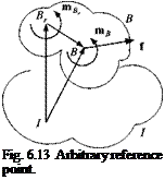
B. Now we force the attitude equation into the same mold by following Grubin.4 Beginning with Eq. (6.38), Newton’s and Euler’s equations are

mBDlDIsBI = f (6.43)

D4BB = mB (6.44)

We transform the angular momentum with the help of Eq. (6.19) to point Br

jBI vB Bl В c »~k/_

І в — * вгш ~m ^bb, D sBBr and likewise shift the moment center to Br using Eq. (6.39)

m/s = mBr – SBBrf

Both transformations are substituted into Eq. (6.44) and yield

D!{lBBrшВІ) – mBDSBBD, sBBr) = mBr – SBBJ

Applying the chain rule to the second term and using Eq. (6.43) for the last term provides

D1 (1%швг) – mB SBBrDl DlsBBr = mBr – mB SBBrDl D1sBl

Introducing the vector triangle from Fig. 6.13 and taking the rotational derivative twice,

DlD! sBl = DID, sBBr + DlD‘sBr,

and substituting into the last term provides, after canceling two terms,

Dl(lBB^BI) = mBr – mBSBBrDlD’sBrl (6.45)

We have arrived at Euler’s law referred to an arbitrary body point Br:

D1 (lBBru>BI) = mBr – mBSBBrD’v^ (6.46)

The last term adjusts for the fact that Br is not the c. m. The linear velocity v lB couples into the translational equation derived earlier [see Eq. 5.27)]:

Подпись: mB D'v’B = f — mB

Подпись: Fig. 6.13 Arbitrary reference point.

flB! flBIsBBr centrifugal acceleration +(Dl ftBI)srsB, angular acceleration

and the angular velocity и)BI connects back to the attitude equation. Both equations constitute the complete set of six-DoF equations of motion for an arbitrary refer­ence point of body B. They are more complicated than the standard set Eq. (6.38). If Br is the c. m. B, then sBB =0; the two equations uncouple and reduce to Eq. (6.38).

Example 6.9 Physical Pendulum with Moving Hinge Point

Problem. You probably have solved this nontrivial problem before by the Lagrangian methodology. I will demonstrate here that Eq. (6.46) leads in a straight­forward manner to the solution.

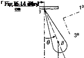
The physical pendulum with mass mB and MOI IB swings about the hinge point Br, which in turn is excited by the forcing function [,vB = [A sin cot 0 0] in inertial coordinates, as indicated in Fig. 6.14. What is the differential equation that governs the dynamics of the pendulum? The MOI is given in body coordinates

Euler’s law, like Newton’s second law, must be referred to an inertial frame and, for simplicity’s sake, should be referred to the vehicle’s c. m. Yet, just as in Sec. 5.3, we ask what are the correction terms if we change to a noninertial reference frame or an arbitrary body point.. Noninertial reference frame

[I§ ]B = [diag(/i, І2, /3)], and the displacement of the c. m. of the pendulum В from the hinge point by [sBB ]B = [0 0 /].

Euler’s law, like Newton’s second law, must be referred to an inertial frame and, for simplicity’s sake, should be referred to the vehicle’s c. m. Yet, just as in Sec. 5.3, we ask what are the correction terms if we change to a noninertial reference frame or an arbitrary body point.. Noninertial reference frame

Solution. To solve the problem, we express Eq. (6.45) in body coordinates with the exception of the inertial acceleration:

where [®B/]B =[0 0 0], [mBr]B = [0 —mBgl sin# 0], and [d2sBr//dt2]7 = [—Aco2 sin cot 0 0]. Multiplying the matrices yields the equation of motion

hd + mBgl sin в = тв IA со2 sin cot cos в

If you have tried to solve this problem before by the conventional method, you will agree that my method is easier.

After having dealt with the more important case, namely the free-flight attitude equations, we consider point R of Eq. (6.35) to be simultaneously a point of the body and the inertial reference frame, but not necessarily the c. m. A body with a contact point on the ground, the so-called top, can serve as an example.

Free Flight

Free Flight

Let us begin by summing Euler’s law Eq. (6.32) over all particles of a rigid body

and do the same for its alternate form Eq. (6.33)

Free Flight(6.34)

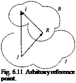
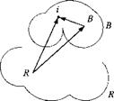
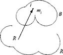
where all internal moments cancel each other and only the external moments remain. The linear velocity was replaced by its time derivative of the displacement vector s,/. Introduce for the time being an arbitrary reference point R (see Fig. 6.11) of the rigid body В into Eq. (6.34):

*;/ = Sm + Sri

We obtain six terms:

^2 D’ (m. SjtD1 slR) Term (1) + D1 (т^тВ’sRI) Term (2)

+ ]T D’ (m, SmD’sK,) Term (3) + J2D’ (m‘ Term (4) (6.35)

І І

= ]T(W,)Term (5) + £($«/,)Term (6)

At this point we split the treatment into the two cases. First, we confine the reference point R to the c. m. В and develop the free-flight attitude equations. Afterward, we let R be any point of body В and assign it also as a point of the inertial frame I, thus addressing the dynamics of the top.

Let us modify the six terms of Eq. (6.35). The inner rotational derivative of the first term is transformed to frame B, and because В is a point of frame B, DBsiB = 0.

Term (1):

Y^D^nuSmD’sis) = ^Г/У[тЛл(/Лш + ГУл)] =

І І І

Referring back to Eq. (6.22), we conclude that the term in parentheses is the MOI IBB of the vehicle multiplied by its inertial angular velocity uinl, and therefore

Term (1) = D,{lBBu:BI)

Term (2):

D’^SbiD^b!) = SBID,(mBvIB)+mBD, SBIvIB = SBID,(mBvIB)

+ mBVBvB = SB1DI(mBv, B)

because the cross product is zero.

Term (3):

Подпись: Dl= 0

because В is the c. m. Term (4):

Подпись: = 0‘ED’imiSBi&Su,) = D1 БШ = Dl SBiD‘ y^ ni, slB

because mt is constant and В is the c. m. Term (5):

total external moment. Term (6):

£>B//,) = SB, f

І

because all internal forces cancel. The modified Terms (2) and (6) express Newton’s second law premultiplied by SBj and are therefore satisfied identically (SBi is
generally not zero). From the remaining Terms (1) and (5) we receive our final result:

D‘(lBBu>Bl) =mB (6.36)

where according to Eq. (6.23) = lBB is the angular momentum of body В

wrt the inertial frame and referred to the c. m. Euler’s law for rigid bodies states therefore that the time rate of change relative to the inertial frame of the angular momentum lBB of a rigid body referred to its c. m. is equal to the externally applied moment m B with the c. m. as reference point

D’lBB’ = mB (6.37)

Equation (6.36) does not include any reference to the linear velocity or acceler­ation of the vehicle. What a fortuitous characteristic! Euler’s law is applied as if the vehicle were not translating. This feature is referred to as the separation theo­rem. Just as linear and angular momenta can be calculated separately, then so can the translational equations of motion be formulated separately from the attitude equations. Newton’s second law, Eq. (5.9), and Euler’s law, Eq. (6.36), deliver the fundamental equations of aerospace vehicle dynamics

mB D’vg = /, D1 (Іввшв1) = mB

and with the compact nomenclature of linear and angular momenta

D1 pB = f, D‘lBI = mB (6.38)

The key point is the c. m. В. It serves as the focal point for the linear momentum pB, encompassing all mass of body В as if it were a particle. For the angular momentum lBB it is that reference point which separates the attitude motions from the translational degrees of freedom. As I will show, without the c. m. as reference point the equations of motion of aerospace vehicles are more complex.

As ahistorical tidbit, I want to mention that the equations of motion (6.38), which we like to call today the six-DoF equations, have been known for quite some time. In 1924, while aviation was still in its infancy, R. v. Mises published the “Bewe – gungsgleichungen eines Flugzeuges,” buried in his so-called Motor Rechnung? He presented the translational and attitude equations in one compact formalism, already transformed to body coordinates, and identified the key external forces and moments. There we even find the inception of small perturbations and linearized equations of motion for an airplane.

Example 6.7 Aero Data Reference Point

Frequently, the aerodynamic and propulsive data are not given relative to the c. m. but to an arbitrary reference point of the aircraft or missile. If you have been involved in wind-tunnel testing, you have dealt with the moment center of the sting balance, which is usually nowhere close to the yet unknown c. m. of the flight vehicle. Or, as the space shuttle bums fuel during its ascent, large shifts of c. m. occur. In each case we need to modify the right side of Eq. (6.37).

Figure 6.12 shows the aerodynamic force / and moment mBr acting on the fixed reference center Br. To calculate the moment mB, referred to the c. m. B, we

Подпись: В B„ Fig. 6.12 Moment centers.

determine the torque SBref caused by changing the origin of the force vector /, and add the free moment vector mB, :

mB = mBr + SBref (6.39)

Substituting Eq. (6.39) into Eq. (6.37) yields Euler’s equation of motion referred to the c. m. B, but with the aerodynamics referenced to the arbitrary point Br

D! lg’ = mBr + SBrBf (6.40)

For an aircraft and missile the displacement vector s Br в most likely will change in time, as the c. m. shifts during flight. Similar adjustments are made if the propulsion moment center changes.

Example 6.8 Attitude Equations for Six-DoF Simulations

Missile simulations use Euler’s equation in a form that accommodates aerody­namic moment coefficients and the MOI tensor in body coordinates. We transfer the rotational time derivative of Eq. (6.36) to the body frame В

DB(lBBu>BI) + QBIIB u>Bl = mB

and pick body coordinates ]B

DB([lB]B[coBI]B) + [QS/]B[/#]%B/]B – [mB]B

Free Flight Подпись: BI^B[lB]B[wBI]B Подпись: [mB] Подпись: (6.41)

Applying the chain rule to the first term and realizing that the MOI of a rigid body remains unchanged in time, [d/§/df]s = [0], we get the desired equations for programming:

This is the attitude equation most frequently found in six-DOF simulations.

Euler’s law according to Goldstein

The prevalent opinion of most books on classical mechanics or dynamics reflects the Newtonian viewpoint. I cite Goldstein2 only as an example. Actually, it was Daniel Bernoulli who is­sued the first account coinciding with Euler’s publication in 1744. Accordingly, the angular momentum equation can be derived from Newton’s linear momentum law.

Starting with Eq. (5.6), premultiply Newton’s law for a particle і by the skew – symmetric displacement vector S, y:

SuD1 (nijv’) = Suf,

If we can show that the left side equals that of Eq. (6.33), we have obtained Euler’s law. Apply the chain rule to the left side of Eq. (6.33):

D1 (miSuv’i) = niiD1 Snv I + SuD1 (m;v/)

= niiV’vl + S,/D'(ot, v,;) = SuD’ {m, v[)

Because the vector product of v with itself is zero, the equality is established. Therefore,

D1 {m і Suv[) = Sufi

and with the angular momentum already introduced l, = and moment

тц = Sufi we §et Euler’s law:

Df’j = ma

Подпись: Fig. 6.11 Arbitrary reference point.

Again we are faced with the choice of the inertial frame. The options we con­sidered for Newton’s law are also pertinent here. Most often, for near-Earth simu­lations, we use the J2000 reference frame. If our vehicle is hugging the Earth, we can use the Earth itself.

I proceed now to derive two formulations that are most applicable to the modeling of aerospace vehicles. The first case represents Euler’s law of a rigid body referred to its mass center. This is the basis for the attitude equations of flight vehicles. The other formulation, useful for gyro dynamics, is Euler’s law of a rigid body referred to a point that is fixed both in the body and inertial frames and need not be the center of mass.

Two Approaches

Just as Newton’s second law describes the translational degrees of freedom of a flight vehicle so does Euler’s law govern the attitude degrees of freedom. Its origin is attributed to Euler and is considered either a consequence of Newton’s law (Goldstein) or a fundamentally new principle of dynamics (Truesdell).

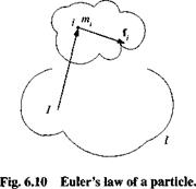
6.3.1.1 Euler’s Law according to Truesdell. Truesdell,1 having conducted a thorough historical research, concluded that Euler’s law in its embryonic form is based on a publication by Jakob Bernoulli (1686), predating the Newtonian laws by one year. Euler polished Bernoulli’s ideas and formulated the angular momentum law as an independent principle of mechanics in 1744. In its elementary form we state it first for a particle (refer to Fig. 6.10).

The inertial time rate of change of angular momentum about a point is equal to and in the direction of the impressed moment about the same point. Consider a particle m,-, displaced from the reference point I by s,-/ and moving with the linear velocity v wrt the inertial frame I. Its angular momentum is Vu — niiSuV-, and the impressed moment relative to point I is т. ц = S,■//,-, where /; is the force acting on the particle.

Euler’s law for such a particle states that the time rate of change wrt the inertial frame I of the angular momentum lj equals the external moment mu:

D’llj = mu (6.32)

and expanded

(6.33)

Two Approaches

On each side of the equation is a vector product of the displacement vector s u with either the linear velocity vf (related to the displacement vector by v = D/s,/) or the force /,.

We introduced a new vector, the moment Шц acting on particle і wrt a point 1. It should not be confused with the scalar m;, the mass of particle і. Now let us turn to the other interpretation.

Euler’s Law

Rapidly we reach the climax of Part 1. Its first pillar is Newton’s second law, expressing the translational dynamics of aerospace vehicles using the linear mo­mentum. With the angular momentum defined we are prepared to formulate Euler’s law, the second pillar of flight dynamics.

We will begin with a historical argument that splits the dynamicists into two camps, the Newtonians and the Eulerians, though the consequences for modeling and simulation are zilch. The particle again will serve the elemental formulation, from which we derive two forms of Euler’s law. Most important for us is thefree – flight exposition, serving all aerospace vehicle applications. The other form, the spinning top with one point fixed, is more of historical and academic significance. Dealing with clustered bodies will be a venture for us. Fortunately, most air – and spacecraft contain spinning bodies with fixed mass centers. These arrangements can be treated in a straightforward manner. For moving bodies the formulation of Euler’s equation gives us access to many challenging modeling tasks.

Angular Momentum of Clusters of Bodies

Most aerospace vehicles consist of more than one body. Aircraft have, besides their basic airframe, rotating machinery like propellers, compressors, and turbines; and, as moving parts, control surfaces and landing gears. Missiles possess control surfaces and sometimes even spinning parts for stabilization. Certainly, you have heard of the Hubble telescope and its control momentum gyros, which point the aperture within a few microradians.

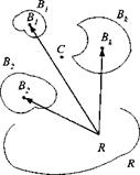
To calculate the total angular momentum, we could simply sum over all of the particles of all of the bodies in the cluster. This approach would bring no new insight. Instead, we derive a formula that takes the individual known angular momenta and combines them to form the total angular momentum (see Fig. 6.9).

Theorem: The angular momentum of a collection of rigid bodies B^, к =

1, 2, 3,… (with their respective centers of mass В*) relative to a reference frame R and referred to one of its points R is given by

Подпись: (6.24)4”‘‘ = £ {П>ак+»"‘s«,0

к

Angular Momentum of Clusters of Bodies

Fig. 6.9 Cluster of rigid bodies.

The individual points В* can be moving relative to each other, but the bodies themselves must be rigid.

Proof: The proof follows from the additive properties of angular momenta [Eq. (6.17)], and the separation into rotary and particle terms [Eq. (6.18)]. To get the total angular momentum, we sum over all individual bodies

_ ‘ jBkR

lR ~ / ,lR

к

and adopt Eq. (6.18) for each body В*

lBRtR =IBBl^R+mB^SBlRvl

to prove the theorem

к

Equation (6.24) makes a general statement about clustered bodies. For many applications, like aircraft propellers, turbines, helicopter rotors, dual-spin satellites and flywheel stabilizers, this relationship can be simplified. In these cases the c. m. of the individual bodies are mutually fixed and so is the common c. m. Introducing this common c. m. C as reference point leads to a simpler formulation.

Theorem: If the common c. m. C of the cluster of bodies T. B*. is introduced

as reference point and if the individual c. m. B>: do not translate wrt C, then the angular momentum of the entire cluster wrt to the reference frame R and referred to the common c. m. C is

lcBtR = + (Y, rnB>SBkCSBtc^ u, CR (6.25)

Compare Eqs. (6.25) and (6.24). The linear velocity vRt does not appear any longer because we adopted the common c. m. (just as in the single-body case). Following earlier convention, we distinguish the two terms as rotary and transfer
contributions. The second term concentrates the mass of body frame Bk in its c. m. Ви for the angular momentum calculation. According to Eq. (6.8), derived from the Huygen’s theorem, the term in parentheses is the MOI of all of the individual body masses mBk referred to the common c. m. The vector uiCR relates the angular velocity of frame C, consisting of the points Bk, to the reference frame R.

Proof: To prove this theorem, some stamina is required. The easier path is to accept the theorem and drop down to the example. For the proof we take three steps:

1) Introduce the vector triangle to include the total c. m. C

sBkR = SBkC +SCR

into Eq. (6.24)

{RBtR — ^2ііВвкшВкЕ + £«B‘(^c + SCr)Dr(sBiC +sCr)

Angular Momentum of Clusters of Bodies

and execute the multiplications

Подпись: к (6.26)

Angular Momentum of Clusters of Bodies

The last two terms are zero because C is the common c. m. Let us demonstrate this fact for the last term. Because the body’s mass is a constant scalar, it can be brought inside the rotational derivative, and the summation can be exchanged with the time derivative, resulting in

2) Now let the arbitrary reference point R be the common c. m., then Sen — Scc = 0, and the second term of Eq. (6.26) is zero. We are left with two terms:

Подпись: кПодпись: кAngular Momentum of Clusters of Bodies(6.27)

The first term is the sum of all rotary angular momenta. The second term is ex­panded by transforming the rotational derivative to the frame C:

Подпись: к к

£mBkSBkcDRsBkc = £«tB‘SBtc(£>cSBtc + ftCRSBkc)

— ^^mBk^BkcDcSBkc + m Вк S Bk(‘^lCRs вк с

3)

Angular Momentum of Clusters of Bodies

In addition, because the individual c. m. Bk and the common c. m. C are fixed in frame C, DcsBkC = 0, and the first term is also zero, leaving Eq. (6.27) with

The last term can be modified by a procedure we have used before [see Eq. (6.21)], and thus the proof is complete:

lcBtR = T, lfaBk* +

Подпись: llBtR =52/B‘U>b** + к Подпись: У^mBl,SBtcSBkc Подпись: B,R

Quite frequently, in aerospace applications one of the bodies is the main body, supporting all other spinning bodies. It takes on the function of frame C, but its own c. m. is not the common c. m. C. If that body is called Вi, then the theorem becomes

Example 6.6 Propeller Airplane

Problem. Determine the angular momentum of a single propeller-driven air­plane wrt the inertial frame I. The propeller P with mass mp and c. m. P is displaced from the reference point T at the tip of the airplane by SpT. The c. m. В of the airframe В with mass mB is displaced from T by Sbt- Their MOI are Ip and Ip and their angular velocities uipn and шш, respectively.

The components of the tensors in airframe coordinates are for the propeller

Co

II

1

0 О

<N

° ^

►5 °

1 ___

, [vPB]B =

3 °

1____

, [■У/>г]В =

Spn

0

1

О

О

*■4

0

0

and for the airframe

Iflii

0

0

ІВ2

1

CO

CQ О

, WBI}B =

1

_______ 1

. [^вг]в =

SBTl

0

Івп

0

ffl33

r

0

Solution. To determine the total angular momentum, we apply Eq. (6.25), referred to the inertial frame /:

tcBkI = Т, ІВвУкІ + (Y, mBkSBkCSB^ 0JCI

We are dealing with the propeller P and the airframe В serving as frame C:

lcBiI = Ір(шрв + шш) + Іввшві + mp S pc SpCu! BI + mB SBCSBCu>BI (6.28)

To determine the individual c. m. displacement vectors sPc and sBc, we first get the location of the common c. m. C from the reference point T

Подпись: ScrmBsBT + mpSpT

im8 + mp)

and then the desired c. m. locations wrt the common c. m.

Spc = Spr — Sct $BC = Sflr — Scr

Angular Momentum of Clusters of Bodies Подпись: (6.29)

By eliminating scr.

We have derived the solution in an invariant form, represented by Eqs. (6.28) and

(6.29) .

Angular Momentum of Clusters of Bodies

For developing the component form, we express Eq. (6.28) in airframe coordi­nates ]B

(6.30)

and then insert the components. Multiplying the matrices yields

№BtI]B –

Ip(p + шр) + ІвіР + Івізг

(ІР2 + iBi)q

+ {mP4a +mBs2Bcl)

"О"

ч

(ІРЗ + ІВ2з)г + ІВзР

r

(6.31)

where spci and ідеї are the first components of the vectors in Eq. (6.29). The second term affects only the pitch and yaw angular momenta.

Frequently, several simplifications are justified. With mp p and mpSpC1 » mBs2Ba we can reduce Eq. (6.31) to

№вк1}в =

Ipo>P + ІвпР + Івізг (Ір2 + lBi)q

+ m? sPC

‘О

q

(Ірз + ІвззУ + 1взР

г

More drastically, the second term and the product of inertia Ів в are sometimes dropped (only the principal MOIs IBi, IB2, and /B3 are left), and the MOI of the propeller is assumed much smaller than that of the airframe. Then we arrive at a popular representation that just adds the angular momentum of the propeller to that of the airframe:

Подпись: [/cBkI]B1рШр + IBp ІВ2Ч ІВЗГ

Another entity, the angular momentum, has joined our collection of building blocks, but it is more sophisticated than the other items. It requires three defining super – and subscripts. The first frame represents the material body, followed by an arbitrary reference frame and a reference point. Frequently, the reference point is the c. m., and an inertial frame serves as reference. This situation arises in particular when we formulate the attitude equations of flight vehicles from Euler’s law.

Angular Momentum of Rigid Bodies

In most of our applications, the collection of particles can be assumed mutu­ally fixed. This idealization, called a rigid body, is physically not realistic because molecules, even in solid matter, are oscillating. However, our macroscopic perspec­tive permits this simplification. We need to be careful only when bending and vibra­tions (flutter) di stort the airframe to such an extent that aerodynamic and mass prop­erties are significantly changed. Here, we take advantage of the rigid-body concept.

Theorem: The angular momentum lHRR of a rigid body В wrt to any reference

frame R and referred to reference point R can be calculated from two additive terms:

If = IBBLJBR + mBSBRvR (6.18)

The first term is the angular momentum l^R of body В wrt to reference frame R and referred to its own c. m. B, lBR = Івшвк, and the second term is a transfer factor accounting for the fact that R is not the c. m. Replacing the linear velocity by its definition Vj – DRsBR results in another useful formulation:

Ir — і ВШ +W ^brU SBR (6.19)

Proof: From Fig. 6.8 we derive the vector triangle and then take the rotational derivative wrt the reference frame R:

Angular Momentum of Rigid Bodies

Fig. 6.8 Center of mass.


Substitute both into Eq. (6.17):

1Brs = + SBR){DRsm + Z7sSbr)]

Before we multiply out the terms, we use the Euler transformation to shift the rotational derivative of DRs, n to the В frame DRsiB — DBsiB + flBRsiB and take advantage of the rigid-body assumption, i. e., DBsiB = 0 (all particles are fixed wrt the c. m.):

Подпись: У, m, [(S/л + SBR)(flBRSiB + DRSbr)

iBR

lR

Angular Momentum of Rigid Bodies(6.20)

The last two terms vanish because В is the c. m. The first term on the right-hand side is modified by first reversing the vector product and then transposing it to remove the negative sign:

У^ miSiBilBRsiB = – У^ miSiBSiBu>BR = У"’ mjSiBSiB<jjBR (6.21)

І І І

Eureka, we have unearthed the MOI tensor £]. ntiSiBSlB = /1 [see Eq. (6.1)]! The first term therefore becomes

Angular Momentum of Rigid Bodies(6.22)

Angular Momentum of Rigid Bodies

The second term of Eq. (6.20) is simply

Angular Momentum of Rigid Bodies

Substituting these terms into Eq. (6.20) yields

and proves the theorem.

The angular momentum of Eq. (6.18) consists of a rotary part Ibujbr with the angular velocity uiBR of the body wrt the reference frame and a transfer term mBSfiRvfj with all mass concentrated at the c. m. If the reference point is the c. m. itself, SBb — 0, and the transfer term vanishes:

І в =Івш (6.23)

Because the displacement vector sbr is not part of the calculations any longer, the angular momentum has become independent of the translational motion v B of the body’s mass center. What a welcome simplification! The c. m. as reference point separates the translational dynamics from the attitude motions.

Example 6.5 Change of Reference Frame

Problem. Suppose the angular momentum lBB’ of vehicle В wrt the J2000 inertial frame I and referred to the vehicle’s c. m. В is known only wrt the Earth frame E, i. e., lBnE. What is the error if we neglect the difference?

Solution. Expand the angular velocity uinl — uiBE + uiEI and substitute it into Eq. (6.23):

lBI _ jB BE, jB El lB — ІВШ + 1 ВШ

The first term on the right-hand side is I%ojbe — lBBE, and therefore the error is

tb, ,ei lBu> .

Do you appreciate now the significance of the MOI? Because it is a second – order tensor, it acts like a transformation that converts the angular velocity vector into the angular momentum vector. However, the MOI being a symmetrical tensor alters not only the direction but also the magnitude of uiBR.

Angular Momentum

The angular momentum is the cousin of linear momentum. If you multiply the linear momentum by a displacement vector, you form the angular momentum. That at least is true for particles. By summing over all of the particles of a body, we define its total angular momentum. Again, introducing the c. m. will not only enable a compact formulation and simplify the change of reference points, but will also justify the separate treatment of attitude and translational motions. We close out this section with the formula for clusters of bodies, both for the common c. m. and an arbitrary reference point.

6.2.1 Definition of Angular Momentum

The definition of the angular momentum follows a pattern we have established for the linear momentum (Sec. 5.1). We start with a single particle and then em­brace all of the particles of a particular body. Rigid-body assumptions and c. m. identification will lead to several useful formulations.

To define the angular momentum of a particle, we have to identify two points and one frame: the particle i, the reference point R, and its reference frame R (see Fig. 6.7).

Definition: The angular momentum lfR of a particle і with mass m, relative

to the reference frame R and referred to reference point R is defined by the vector product of the displacement vector siR and its derivative DRsm multiplied by its

Angular Momentum

mass M;:

І ж = miSiRDRsiR = miSiRvf (6.15)

Because the rotational derivative of s, s is the linear velocity of the particle, DRslR = vf and mtvf — pf is the linear momentum; we can express the angular momentum simply as the vector product of the displacement tensor and the linear momentum

lfR = SmP* (6-16)

The direction of the angular momentum is normal to the plane subtended by the displacement and the linear momentum vectors. (Any particle that is not at rest has a linear and angular momentum; it is just a matter of perspective. If the reference consists only of a frame, it exhibits linear momentum properties only. If a reference point is introduced, it displays also angular momentum characteristics.)

A body B, not necessarily rigid, can be considered a collection of particles і. The angular momentum of this body В relative to the reference frame R and referred to the reference point R is defined as the sum over the angular momenta of all particles

if = Yl* = Ym’s‘«DRs’« = YmiSiRVf = Ys‘rp’ (6Л7)

і І І і

Notice the shift of the subscript і in JA lfR to a superscript В in lBR, reflecting the gathering of all particles into body B.

Inertia Ellipsoid

The MOI tensor portrays a vivid geometrical interpretation, which is useful for the investigation of rigid-body dynamics. Being a real symmetric tensor, it has several important characteristics: it is positive definite, has three positive eigenval­ues, has three orthogonal eigenvectors, and can be diagonalized by an orthogonal coordinate transformation with the eigenvalues as diagonal elements.

As we have seen, the axial MOI about axis n through reference point R is according to Eq. (6.3) in body coordinates

/Я = [й]*[/!]Я[Л]*

= І\П + hin + /33П3 + 2/і2«іП2 + 2/23И2П3 + 2/31П3И1 (6.11)

Interestingly, this scalar equation in quadratic form has a geometric representation. Because the eigenvalues of [/B]B are always real and positive, the geometrical surface, defined by Eq. (6.11), is an ellipsoid. If we introduce the normalized vector [х]в = пвIy/Tn, we obtain the equation for the MOI ellipsoid:

1=ИВ[7|]ВМВ

— hX + І22х2 + /33*3 + ^I2XX2 + 2/23X2X3 + 2Ij, iXt, X (6.12)

Referring to Fig. 6.5, x is the displacement vector of a surface element relative to the center point R. A large value of |jc| means that the axial MOI /„ about this vector is small and vice versa.

If the body axes are principal axes, then [IB]B is a diagonal matrix, and Eq. (6.12) simplifies to

1 — hx + І2Х2 T /3X3 (6.13)

Подпись: 1 _ 1 7n' b~7r2 ’ Подпись: (6.14)
Inertia Ellipsoid

where 11, /2, /3 are the principal MOIs. They determine the lengths of the three semi-axes of the MOI ellipsoid

Inertia Ellipsoid Подпись: 2B

The radius of gyration pn is that distance from the axis at which all mass is concentrated such that the axial MOI can be calculated from /„ = pynf. We use

it to get another expression for the surface vector:

Inertia Ellipsoid

Thus, the magnitude of the vector to a point on the inertia ellipsoid is inversely proportional to the radius of gyration about the direction of this vector. For example, in Fig. 6.5 the MOI about the third axis is greater than that about the second axis.

The directions of the eigenvectors e,e2, «з are the principal axes. If they are known in an arbitrary coordinate system [e]A, [e2]A, [ез]А, then the transforma­tion matrix

[ci]A

[T]DA = [e2]A

_ [c3]A.

transforms the MOI tensor into its diagonal form

[/diagonal]0 = [Г]°А[/]А[Ї]Ш

with the eigenvalues as principal MOIs.

Example 6.4 Shapes with Planar Symmetry

If a body with uniform mass distribution has a plane of symmetry, then one of its principal axes is normal to this plane. We validate this statement by the example of Fig. 6.6. The wing section has a plane of symmetry coinciding with the Is, 3® axes. According to Eq. (6.2), the products of inertia containing the components SiR2 are zero because their right and left components cancel. Thus

/и 0 I13

[/f]B= 0 h 0

/із 0 hi

and I2 is the principal MOI.

At no time did I assume the body to be rigid. Definitions and theorems of this section are valid for nonrigid as well as rigid bodies, and therefore, elastic structures are not excluded. However, a difficulty arises describing a frame for such an elastic body. Because, by definition, frame points are mutually fixed, we cannot use the particles of an elastic structure to make up the body frame. Instead, we have to idealize the structure and define the frame to coincide either with a no-load

Inertia Ellipsoid

situation, the initial shape, or some average condition. Yet, do not be discouraged! The definition of the MOI does not rely on a body frame, but rather a collection of particles, mutually fixed or moving, which we designate as B. Only in the future, when we use the body as reference frame of the rotational derivative, do we need to specify a true frame. In those situations we will limit the discussion to rigid bodies.

The MOI joins the rotation tensors in our arsenal of second-order tensors. Both have distinctly different characteristics. Whereas the MOI tensor models a physical property of mass, the rotation tensor relates abstract reference frames. Their traits are contrasted by symmetrical vs orthogonal properties. However, both share the invariant property of tensors under any allowable coordinate transformation; and in both cases points and frames are sufficient to define them. Now we have reached the time to make the MOI come alive by joining it with angular velocity to form the angular momentum.