Category Modeling and Simulation of Aerospace Vehicle Dynamics

Transformations

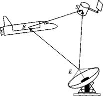
Observing in the night sky a satellite still illuminated by the sun and an airplane flashing its strobe light, one may get the impression that both stay aloft by the same forces. However, we know better. Aerodynamic forces carry the airplane, but what holds up the satellite? You would answer, “the centrifugal force of course!” What is that centrifugal force? Is it a surface force, like aerodynamic lift, or a volume force, like gravity? Is it a force that should be included at the right-hand side of Newton’s law? None of the above. It is all a matter of reference frame. Because you are not standing on an inertial reference frame, an apparent force, the centrifugal force, keeps the satellite from falling at your feet. However, if you were sitting on the ecliptic, you would marvel how the Earth’s gravitational pull prevents the satellite from escaping the Earth’s orbit.

Both observations are equally valid. So far we have taken the inertial perspective. Now I will derive the translational equations of motion for noninertial reference

Transformations

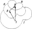
Fig. 5.7 Reference frame R.

frames. Besides the centrifugal force, we shall also encounter the Coriolis force, which gives this transformation its name.

Another situation arises when the c. m. is not the preferred reference point. En­vision a large symmetrical space station with antennas on one side as appendages. It is sometimes advantageous to use the c. m. of the space station as reference point for the dynamic equations, rather than the common c. m. This point transformation is called the Grubin transformation.

Newton’s Second Law

Newton’s second law is the most important tool for modeling aerospace vehicle dynamics. It governs the motions of the c. m. of the vehicle subjected to external forces. We apply it first to a single particle and then to a collection of particles and eventually arrive at a form that is most suitable for our modeling tasks.

For a particle i, Newton’s second law postulates

D’pj = ft (5.6)

The equation states that the time rate of change wrt the inertial frame / of the linear momentum of particle і wrt the inertial frame equals the force act­ing on the particle. Introduce the definition of linear momentum from Eq. (5.1),

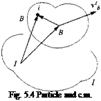
Подпись: Fig. 5.4 Particle and c.m.

pj — m, D’su, into the left side of Eq. (5.6) so that

D1 p – D1 (niiD1 Su) = rtiiD1 D1 su + D’iti^D’su

where the last term is zero because the mass of a particle is time invariant. Now we sum over all of the particles of body B. The internal forces will cancel because of Newton’s third law, but the external forces remain

Y^miDJDIsa = Ytfi (5.7)

І І

Let us introduce the c. m. В of the collection of particles (see Fig. 5.4)

Sir — SiB + $BI

and obtain

D’sw + J^miD’D’ssr = ^/;

І І І

Подпись: ^m^D'siB = YJD,D,(misiB) = D1 D1 J^nusw = 0

With the mass of each particle constant, we can place it inside the rotational derivative and move the summation sign. Because В is the c. m. of all particles, the first term vanishes:

Abbreviating mi — mB and summing over all forces JT/j – = /> we arrive at Newton’s second law for body В relative to the inertial frame /:

mBDID, sBi = f (5.8)

Let us introduce the velocity v’B = D’sbi of the c. m. В wrt the inertial frame I. Newton’s law reads then as follows: The mass mB of body В times the inertial acceleration a’B — D! vlB of its c. m. В equals the resultant external force/.

mBDIv1B = f (5.9)

From this derivation we conclude that the c. m. В of a system of particles m, moves like a single particle В whose mass is the total mass mB, subject to the
force/. Notice that we did not invoke a rigid body assumption, although most of our applications will do so.

Подпись: m Newton’s Second Law

We have formulated Newton’s law in an invariant tensor form, which can be expressed in any allowable coordinate system. For instance, in coordinates ]7, associated with the inertial frame I, we get the ordinary time derivative

For a noninertial coordinate system, say ]B, associated with the body frame B, we transform the rotational time derivative to the В frame via the Euler transformation to get the ordinary time derivative in the ]B coordinates:

= [/]B

+mB[^lBIB[v, BB = [f]B

The acceleration [du^/dfj® is the inertial speed, coordinated in body axes, with its components subjected to the ordinary time derivative. The additional term [Г2й/|й[Т.’д]й is called the tangent acceleration.

As we developed our preferred formulation, Eq. (5.9), we assumed that the body holds onto all of its particles; in other words, the mass is time invariant. If particles are ejected, as for instance by a rocket motor, the linear momentum is changed, resulting in a thrust force. Traditionally, however, that force is moved to the right side of Newton’s law and considered an external force (see Example 5.6). On the left side the mass has become a function of time.

Example 5.2 Trajectory Equations

The translational equations of an aerospace vehicle are directly derived from Newton’s law, Eq. (5.9). With mB the mass of the vehicle, vi the linear velocity of the c. m. relative to the inertial frame /, and the external forces consisting of aerodynamic force fa, propulsive foreefp, and gravitational force mBg, the translational equations are

mBDlvIB = fa + fp + mBg

This tensor equation is valid in any allowable coordinate system. The simplest implementation is in the inertial coordinate system |;

m^v1^1 = [faY + [fp]1 + mB[g]7

However, the aerodynamic and propulsive forces are most likely given in body coordinates ]B and the gravitational acceleration in geographic coordinates ]G. With the two transformation matrices [T]B1 and [7’ |c/ we can formulate the dif­ferential equations for computer programming

Подпись: d v‘B df Подпись: (5.10)Подпись:

Подпись: L

= [f]BI[fa, P]B +mB[T]G,[g]G

where the aerodynamic and propulsive forces have been lumped together. To calcu­late the trajectory, another integration is necessary for obtaining the displacement vector sb/ of the vehicle c. m. relative to an inertial reference point I

D’sbj = vlB

In inertial coordinates

Подпись: dxs/ d? – [4]’ (5-П)

Equations (5.10) and (5.11) are the six differential equations that must be solved, starting from initial conditions, to generate the trajectory traces.

Example 5.3 Translating Inertial Frames

Problem. Newton’s first law states the experiential fact that, unless bodies are subjected to forces, they continue in a state of rest or uniform motion. From Newton’s second law, mBDIvlB = 0, indeed we conclude that the inertial velocity does not change. This statement reflects also on the characteristic of the inertial frame. Newton’s second law holds equally in an inertial frame at rest or at uniform motion in a straight line. Let us prove that fact.

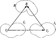
Solution. Figure 5.5 depicts the body В with c. m. В and two inertial frames 11 and I2 with two arbitrary reference points h and /2, respectively. The presup­position of both inertial frames not accelerating relative to each other implies that the mutual linear acceleration and angular velocity are zero:

DhDhshh= 0, fthI] =0 (5.12)

Introduce the vector triangle of Fig. 5.5

*B/i = SBI2 + SI211

into the left side of Newton’s second law, Eq. (5.8),

Newton’s Second Law

mBDhDhsBh= f (5.13)

and obtain

mBDhDhsBh+mBDI’Dhshh = f

The second term on the left-hand side vanishes because of the first premise of Eq. (5.12). The first term is modified twice by Euler’s transformation to the /2 frame, and the second premise of Eq. (5.12) is used

mBDI’DhsBh =mBD,'(DhsBh+nh,’sBi2) =mBDhDhsBh

= mBD,2(DhsBh)+mB£lhIi(Dl2sBl2) = mBDhDhsBh

Summarizing, from Eq. (5.13), with the assumptions of Eq. (5.12), we derived the alternate form

mBDhDhsBll = f

Both inertial reference frames lead to the same dynamic equation. Because either frame /1 or /2 is suitable, all inertial frames, not mutually accelerating, lead to the same formulation of Newton’s second law.

Example 5.4 Two-Body Problem

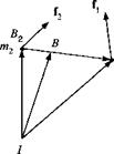
Problem. Given are two particles with masses m 1 and m2, located at B and B2 and subject to the external forces/j, f2 (see Fig. 5.6).

1) Determine the displacement vector sbi of the common c. m. В wrt an inertial reference point I. Express the location of the two masses s в, / and s в, / in terms of sbi and sb, b2-

2) Apply Newton’s second law to both masses individually and then show that (m 1 + ш2)/У D1 s в і =/, + /2 and explain what the meaning of this reduction is.

3) If the point masses are not subject to external forces, then /1 + /2 = 0. What motion does the common center of mass В execute?

4) Let m 1 be the mass of a satellite and m2 the Earth’s mass. Assuming m2»mi and neglecting the acceleration of the common mass center, give the simplified equation of motion of a satellite orbiting the Earth. Summarize the assumption for this simplified single body problem.

Newton’s Second Law

Solution. 1) From the vector triangle in Fig. 5.6, we get the first relationship

SBiB2 = «В,/ ~ SB2I

Because В is the c. m. of both particles, the second condition is (mi + m2)sBi = + m2sB2i

Solve both equations first for sBli (multiply the first by m2 and add both equations),

m2

®в1/=®вН—– ;—- sb1b2 (5.14)

mi + m2

and then similarly for sBl[,

m 1

вb2i ~ sbi——– ;—- Sfiib2 (5.15)

mi + m2

2) Apply Newton’s law to particles B and B2 and substitute Eqs. (5.14) and (5.15), respectively,

Подпись:= m1DIDISBi+-— — – DIDISB1Bi = /1 m 1 + m2

rm&DhB^i = m2DlD’sBi – D! sB]b2 = f2

mi + m2

then add both equations

Подпись:mD1 D’sB, = f, т = т{+т2, f-fi + f2

If В is the common c. m., then Newton’s law is applied as if all mass m = m 1 + m2 were concentrated at the c. m. and acted upon by the resultant force/ =fx + /2.

3) Without external forces Eq. (5.17) becomes

malB = mD1 D‘sB — 0

i. e., the acceleration of the common c. m. is zero.

4) When m2 » mi, from Eq. (5.16) we obtain

mDl DlsBl + mD! D1 s ВіВг = /, and if we assume that the common c. m. В is not accelerated,

miD’D’sBf^ = /1

The reduced single-body problem of a satellite B orbiting Earth B2 can be solved as if the common c. m. is centered in Earth’s c. m. B2. The assumptions are that 1) m2^> m and 2) the common c. m. is not under acceleration.

Example 5.5 Pulse Thruster

Problem. The thruster of a satellite increases with a single pulse the satellite speed from vo to Vf. The total particle count of the satellite is s, and the thruster ejects / number of particles at an exhaust velocity of ve. Assuming that the pulse is instantaneous, what is the increase of the satellite speed Av — 1if — v0l

Solution. Let us start with Eq. (5.6) and sum over all particles and recognize that no external forces are applied:

S+f

T, DlPf= 0

i=l

The total linear momentum is therefore conserved:

S+f

Pf = const

1=1

Divide the particles up into satellite and ejected mass:

s+f s s+f

E p’ = E p’ + E p! =const (5-i8>

/=1 / = 1 i=s–1

We reduce the problem to one dimension in inertial coordinates, label the satellite mass

ms = m,

i = l

and the mass of the ejected fuel

S+f

mF = m,

Before pulse firing, the linear momentum is (ms + mF)vo. The pulse is ejected in the opposite direction at — ve wrt the satellite and (—ve + Vq) wrt to the inertial frame. Afterward the satellite’s linear momentum is msVf and that of the fuel mF(vо — ve). Using Eq. (5.18) in one dimension delivers

(ms + mF)vо = msv/ + mh (vq — ve) = const

Solve for Vf

Подпись: vf =msv о + mFve

Подпись: Av Подпись: msv о + mFve ms Подпись: (5.19)

and the velocity increase is

The higher the exhaust speed ve or the fuel mass m /., then the greater the increase in satellite speed. What happens to the c. m. of the total particle count s + /?

Example 5.6 Rocket Propulsion

A rocket motor ejects fuel particles continuously. We regard Eq. (5.19) as the velocity increase per time interval At caused by the fuel mass expenditure of Am = mF with the total mass of the vehicle m = ms + Am ^ ms. If we formally take the time derivative of Eq. (5.19) and, recognizing that ve and ъу> are constant, we obtain

Av ve Am

Before we can write the thrust equation, we have to address a subtlety in sign change. In the previous example the fact that the linear momentum of the exhaust is opposite to that of the satellite was expressed by the negative sign of ve. Now, with the fuel loss derivative being negative, the exhaust velocity should be positive. Therefore, we change its sign and make the transition to differentials:

Подпись: duПодпись: mПодпись: dtNewton’s Second Law(5.20)

Подпись: /
Newton’s Second Law

This is Oberth’s famous rocket equation, which can be solved by separation of variables:

Solving the integrals with ъу> and m0 as the initial values, the increase in speed An is

A v = v — Vo = veln— (5.21)

m

The rocket’s burnout velocity v increases with increasing mass fraction mo/m and exhaust velocity ve. In engineering applications, fuel flow is usually taken positive and the rocket thrust calculated from Eq. (5.20):

Подпись: (5.22)F — mve

Thus, we have demonstrated how the time rate of change of momentum of rocket propellant produces thrust. This force is moved to the right side of Newton’s equation and portrayed as an external force.

Newton’s second law suffices to model the trajectory of an aerospace vehicle. Deceptively simple to write down in inertial coordinates, it has many variants that become important for applications. We already encountered the formulation in body axis, which gives rise to the tangential acceleration term. Other variations consider noninertial reference frames and points that are displaced from the c. m. We consider such transformations next.

Newtonian Dynamics

Sir Isaac Newton published in 1687 in the Philosophiae Naturalis Principia Mathematica three laws.1 In plain English they postulate the following:

1) Every body continues in its state of rest or of uniform motion in a straight line unless it is compelled to change that state by forces impressed upon it.

2) The rate of change of linear momentum equals the impressed force and is in the direction in which the force acts.

3) To every action there is always opposed an equal reaction.

Newton used the word motion instead of linear momentum to define the second law, but the meaning is the same. Like any researcher he used the scientific method to arrive at this formulation. Observations pointed to hypothesis, and testing con­solidated the theory. After more than 300 years of validation, we certainly are justified to call them natural laws.

However, even laws are constrained by assumptions. Newton’s laws are valid in classical physics, where mass does not exceed that of natural substances and velocities are well below the speed of light. Any transgression requires relativistic expansion that Einstein has provided. Furthermore, as particles assume subatomic size, Heisenberg and Schroedinger2 contributed the framework of quantum physics to explain emerging phenomena. All of these modem extensions however point back to Newton’s classical dynamics, as extreme conditions are reduced to the level of our human experience. For any new dynamic theory to be acceptable, it must contain Newtonian dynamics as a limiting case.

The first law is validated by our experience. We do not notice our own linear momentum unless a wall stops us. The wall exerts the force that kills us (second law). Newton’s third law is important in mechanics because it assures us that internal forces cancel in a collection of particles. However, it is the lesser of the three laws because it fails in classical electrodynamics. For modeling of aerospace vehicle dynamics, the second law is of greatest interest. We therefore refer to it mostly just as Newton’s law.

Interestingly, Newton did not specify a frame of reference in formulating his second law. Others attempted to affix what was called the “luminiferous ether” to his law, until Michelson and Morley2 in 1887 disproved the concept. Thus, wisely, Newton left it to the application to pick the proper reference frame, which we call today the inertial reference frame. From his first law we know that any nonaccelerating frame qualifies equally well; but do they exist? In Chapter З, I suggested using the ecliptic of our sun as inertial reference frame, but we know that our solar system is located in the spiral arms of the Milky Way and therefore accelerating. Other theories suggest that all galaxies are fleeting with increasing speed. Where is the inertial frame? It probably does not exist in absolute terms.

Applications determine the inertial frame. Interplanetary travel requires the he­liocentric frame; Earth satellite trajectories use the ecliptic oriented and Earth – center fixed frame, which we call plainly the inertial frame’, and Earth-bound, low-speed flights can use the Earth frame. Whatever the accuracy requirement of your simulation is will determine the choice of inertial reference frame.

Linear Momentum

Have you experienced your linear momentum lately? Probably not if it remained constant. As an Earthling of 80 kg mass, you were bom with a linear momentum wrt the ecliptic of about 2.66 x 10⁶ kg m/s and because the sun is part of the Milky Way galaxy, you can claim another 4.4 x 10¹⁰ kg m/s of linear momentum. That much should make anybody dizzy, but nobody takes notice. If, however, you travel in a car at 60 miles/h and hit a wall, your 2100 kg m/s change of linear momentum will kill you. It is the time rate of change of linear momentum that creates the force; Newton just reversed the order of cause and effect.

Before we apply Newton’s law, we need to learn more about the linear momen­tum. First we define the linear momentum of a particle, then generalize it for a collection of particles (body) and single out its c. m. For clusters of bodies, we learn how to calculate their linear momentum, again with special emphasis on the common c. m.

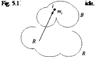
Definition: The linear momentum pf of a particle і relative to the reference frame R is defined by the rotational time derivative wrt to frame R of the displace­ment vector siR multiplied by its mass иг,- (see Fig. 5.1).

pf = mjDRSiR = ttiivf (5.1)

Because the rotational derivative of the displacement vector yields the velocity

vf = DRSjK, we can also state

linear momentum = mass x linear velocity

The linear velocity vector imparts the direction to the linear momentum and also its independence from a specific reference point. The nomenclature reflects that char­acteristic: subscript і is the particle point and superscript R an arbitrary reference frame.

Definition: The linear momentum of a collection of particles В relative to the

reference frame R is the sum over all linear momenta of each particle

Linear Momentum

Linear Momentum

(5.2)

Linear Momentum Подпись: (5.3)

This definition is awkward because it requires knowledge of every particle’s ve­locity. We can simplify matters greatly, by defining the c. m. В of the collection of particles В with total mass mB and specifying its velocity vR. Then, the linear momentum pR of c. m. В wrt the reference frame R is given by

Only the total mass and the c. m. of body В contribute to the linear momentum. The shape and attitude of the body are irrelevant. In effect, Eq. (5.3), in the light of Eq. (5.1), can be interpreted as the linear momentum of a particle with mass mB and linear velocity of point B. One only should add that В has to be the c. m. The simplicity of the notation emphasizes this fact. Let us prove Eq. (5.3) by Eq. (5.2).

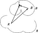
Proof: From Fig. 5.2 we deduce the displacement vector triangle

siR — S ІВ + SBR

Take the rotational derivative wrt the reference frame

DRsiR = DRsiB + Drsbr

Substitute it into the second term of Eq. (5.2), and, because the mass of each particle is constant, it can be brought inside the rotational derivative

Linear Momentum‘Y^miDRsiR = ‘Y^miDRsiB + ‘^2miDRsBR =

Linear Momentum

Linear Momentum

Fig. 5.2 Linear momentum of body B.

The next to the last term is zero because, if В is the common c. m., then JT т^ів — 0, and the rotational derivative of a null vector is zero. Therefore,

Y^miDRsiR = mBvl

І

The collection of particles, forming body B, does not have to be mutually fixed. As long as their c. m. and total mass are known, the linear momentum can be calculated.

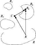
We can extend the computation to a collection of bodies B^, к = 1, 2, 3 … as shown in Fig. 5.3. Because bodies can be regarded as particles as long as their individual c. m. are used as representative points, we can use Eq. (5.2) to sum their individual contributions and calculate the total linear momentum:

PRBk = Y^Pb, = Y^rnBkDRsBkR (5.4)

к к

Introducing the vector triangle for each body, with C the common c. m., and taking the rotational time derivative wrt the reference frame R

DRsekR — DRSBkc + DRScr

yields

РІвк = ^mBtDRSBkC + ^mBtDRsCR

к к

Because C is the common c. m., the first term vanishes as long as the mass of each

Linear Momentum

body remains unchanged:

^т8‘ЛВіС = /)й|^тйіС| =£>*0 = 0

Therefore, the linear momentum wrt a reference frame R of a collection of bodies £/£. к = 1, 2, 3,…, not necessarily rigid but with constant mass, is calculated from the total mass m^ mBl and the linear velocity v* of the common center of mass wrt the reference frame

РІвк = = m^vRc (5.5)

к

We have two methods to calculate the linear momentum of clustered bodies. If we know the individual values, we just add them together [see Eq. (5.4)], or we use Eq. (5.5) if the cluster properties are known.

Example 5.1 Linear Momentum of Reentry Bodies

Problem. A ballistic missile with 3000 kg of payload descends at 12,000 m/s and releases three nuclear warheads at 800 kg each and deploys six 100-kg decoys. Use two ways to calculate the linear momentum of the cluster of reentry bodies.

Solution. Using individual bodies, the total linear momentum is P*Bk=Yl, PBk = YlmBlvBt=( 3x 800 + 6 x 100) x 12,000 = 36 x 106kgm/s

к к

or using the cluster

p%Bk = = 3,000 x 12,000 = 36 x 106kgm/s

both methods lead to the same result.

The linear momentum is an essential ingredient of Newton’s second law. As we add forces to the thought process, the kinematic world view becomes dynamic, and we can study the interactions of force, velocity, and mass in time.

Translational Dynamics

We studied first geometry, then kinematics, and now have amassed enough equipage to investigate dynamics, the effect of force on mass. In this chapter we concentrate on the motions of the center of mass (c. m.), assuming that all mass of a vehicle is localized at that point. The c. m., subjected to forces, describes trajectories in space, as recorded by an observer. Later in Chapter 6 we will model the vehicle as a body and watch it rotate under externally applied moments. Both combined, translation and attitude, convey the full six degrees of freedom of vehicle motions.

The physical law that governs translational motions is Newton’s second law. After 300 years it still has maintained its preeminence in trajectory simulations. Most useful for engineering applications is the formulation: the time rate of change of linear momentum equals the applied external force. Therefore, before we treat Newton’s law in detail we discuss the linear momentum of single and clustered bodies. Then, after deriving the translational equations of motions from Newton’s law we discuss two transformations resulting from changes of reference frame and reference point and conclude the chapter with examples motivated by applications.

Rotation tensor

We have already exploited the close ties between quaternions and tensors of three space. Just glance back at the relationship between the angular velocity quaternion and the angular velocity tensor. Not surprisingly, a similar association exists between the rotation quaternion and the rotation tensor. We could make the derivation from the general rotation quaternion tensor, but prefer a simpler route. I will state the result and prove that it leads to the rotation tensor Eq. (4.12).

Given the rotation quaternion {q) in any allowable coordinate system with the scalar q0 and the vector [q, [see Eq. (4.73)], the rotational tensor [/?] in the same coordinate system is

[R] = ql[E] – [$][*][£] + 2[q][q + 2q0[Q] (4.79)

where [QI is the skew-symmetric version of q. To prove that this formulation leads to the classical form

[/?] = cos £[£] + (1 — cos є)[и][п] + sin £[1V]

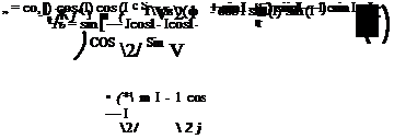
we substitute the rotation quaternion = cos(£/2), [g] = sin(fi/2)[n] into Eq. (4.79)

[R] = cos2 -[£] — sin2 -(и2 + n + n^)[E] + 2sin2 ^[и][п] + 2cos ~ sin ^[JV] = cos e[E] + (1 — cos e)[n][n + sin e[1V] QED

Подпись: L*] =Подпись: (4.80)

Rotation tensor Подпись: 2{яяз + Яо Яг) 2(ягяз ~ ЯоЯ) я1~я]-я+ Яз

Therefore we can use Eq. (4.79) and relate the elements of the rotation tensor to the elements of the rotation quaternion. Substituting [q — q q2 q\ into Eq. (4.79) yields

Rotation tensor Rotation tensor

Specifically, if the quaternion {qBE}’ models the rotation of body frame В wrt Earth frame E, expressed in local-level coordinates, then its rotational tensor is [RDE’ and the direction cosine matrix

The first equation has singularities at x[r = ±90 deg, and the last equation at ф = ±90 deg. But do not despair; because these are just output calculations, you can program around them, and the accuracy suffers only in the close vicinity of the singularities.

The quaternion methodology is complete. Given the Euler angles, initialize with Eq. (4.78) the quaternion differential Equation(4.77), calculate the direction cosine matrix from Eqs. (4.80) and (4.81). Obtain the Euler angles again from Eq. (4.82), as the vehicle flies to its destination. You can acquire the detailed implementation from the CADAC SRAAM6 code, an air-to-air simulation over the flat Earth.

4.3.3.6 Summary. Here you have three methods for solving the funda­mental kinematic problem of flight dynamics. You can use the archaic, compact method of Euler angles, the wasteful direction cosine matrix approach, or the elu­sive quaternion technique. You will need them only in full-up six-DoF simulations, where the solution of the Euler differential equations provides you with the body rates. In three – and five-DoF simulations the lack of attitude equations (Euler’s equations) makes it infeasible and unnecessary to solve the kinematic differential equations—an advantage, if these simple simulations satisfy your need.

Table 4.1 summarizes the options. I favor the latter two methods. Quaternions are well suited for the near-Earth simulations that can use the Earth as inertial frame and employ the local-level coordinate system. In this case the quaternions and the direction cosine matrix are closely linked to the Euler angles. For round and oblate Earth simulations the inertial frame is used, and the [T |,f/ direction cosine matrix is best solved directly because its angles are not the traditional Euler angles.

го

CD


Подпись: MODELING AND SIMULATION OF AEROSPACE VEHICLE DYNAMICS

Table 4.1 Three methods of solving the fundamental kinematic problem in simulations with [u>BE] ~{pqr]

from Euler’s attitude equations


Euler angles


Quaternions


Features


Direction cosines


Rotation tensor
Rotation tensor

_[QiBE} {qbe}


Differential

equation


= [QBI]B[T]BI


Initialization

Directly by фо, во, фо

II

о

‘""й

{<?(!

= 0)} = /(фо, во, фо)

TM

mBL = пф, e, f)

Directly calculated

T)B

1 = (rBE]l

Euler angles

Directly calculated

From [Г]в/

Ф

в

ф

= /(<?0,<?1,92,<?з)

Advantage

Three differential equations.

Transformation matrix cal-

"our

linear differential

Angular attitude calculated

culated directly. Six linear

equations. Simple or-

directly. Direct initialization

differential equations.

thogonality condition.

Disadvantage

Singularity at# = ±тг/2.

Computationally ineffective.

Transformation matrix and

Nonlinear differential

Euler angles not directly

Euler angles not directly

equations. Transformation

available. Initial calcula-

available. Initial calcula-

matrix not directly available.

tions necessary.

tions necessary.


References

Goldstein, H., Classical Mechanics, Addison Wesley Longman, Reading, MA, 1965,

p. 118.

2Wrede, R. C., Introduction to Vector and Tensor Analysis, Wiley, New York, 1963, p. 169.

3Wundheiler, A., “Kovariante Ableitung und die Cesaroschen Unbeweglichkeitsbedin – gungen,” Mathematische Zeitschrift, Vol. 36, 1932, pp. 104-109.

4Zipfel, R H., “On Flight Dynamics of Magnus Rotors,” Dept, of the Army, Tech­nical Rept. 117, Defense Technical Information Center AD-716-345, Cameron Station, Alexandria, VA, Nov. 1970.

5 Hamilton, W. R., “On a New Species of Imaginary Quantities Connected with a Theory of Quaternions,” Dublin Proceedings, Vol. 2, No. 13, Nov. 1843, pp. 424—434.

Problems

4.1 Orthogonality of rotation tensors. Property 4 states that the rotation tensor is orthogonal. The proof suggested using the orthogonality property of TMs. You are to develop a direct proof employing the rotation tensor.

4.2 Elevator rotation tensor. The hinge line of the elevator E is parallel to the 2B axis of an aircraft B. The deflection angle Se is measured positive when the trailing edge moves downward. Derive [RFBB, the rotation tensor of the elevator wrt the airframe, in aircraft coordinates.

4.3 Tip speed of missile fin. A missile В executes rolling motions wrt the Earth frame E that are recorded by the onboard INS as <p(t) = cot, with со a constant. Derive the rotational tensor [/?B£((/>)]B and the angular velocity tensor [QBB]B, both in body coordinates. What is the velocity | vFB of the tip T of the control fin, which is displaced

[5їі]В = [-2 0.5 0] m

from the missile c. m. B1 The missile velocity is

[uf]B = [350 0 0] m/s

and the angular rate со — 100 deg Is (Solution: vF]B = [350 0 0.87] m/s).

1B

Rotation tensor

4.4 Tetragonal tensor is orthogonal. Show that the tetragonal tensor R9о = tin +N is orthogonal, where n is the unit vector of rotation and N its skew-symmetric form.

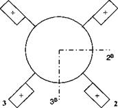
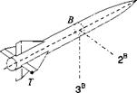
4.5 Control surface forces. A missile is steered by four control surfaces, arranged and numbered as shown in the figure, with positive deflections down as indicated. Wind-tunnel data on control effectiveness are not available, but the force /j on fin #1 was measured as a function of its deflection. If all four fins are deflected by the same amount in the positive direction, what is the total force / (missile incidence angles are zero)? Before you develop the component form, first obtain the invariant tensor.

4 1

Rotation tensor

(a) You will need the tetragonal rotation tensor K90. If b 1 is the base vector of the missile parallel to the missile centerline, show that the tetragonal rotation tensor is R90 = P + B1, where P = bb and B is the skew-symmetric form of b. Also, review the reflection tensor, given earlier M = E — 2P (see Sec. 2.3.6).

(b) Express the total force vector/ in terms of/,, /г90, and M.

(c) The force on fin # 1, with a deflection of 10 deg, was measured as [/j]f =

[—2.2 0 — 11] N in the fin coordinate system, defined by lf parallel to 1B,2F

parallel to the fin shaft and positive out, with the shaft rotated 45 deg from the 1B, 3B plane. Calculate the total force [/]B in missile body coordinates.

4.6 Missile launch. A missile M separates from and aircraft A. The attitude of the missile centerline m relative to the aircraft centerline a 1 can be expressed in terms of the rotation tensor RMA with time-dependent elements: mt = R(t)MAai. From telemetry data the yaw and pitch angles jt, в of the missile relative to the aircraft are known. Derive the rotation tensor [RMA]A in aircraft axes and calculate the instantaneous axis of rotation [nA and the rotation angle e. Is the rotation axis defined at the start of separation?

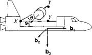
4.7 Manipulator arm. Initially, a satellite is stowed in the space shuttle bay with its symmetry axis *i parallel to the vehicle base vector b . The manipulator arm of the space shuttle deploys the satellite through an upward rotation в about the point X, followed by a rotation about point Y, that brings the satellite’s S| axis parallel and in the direction of the body base vector 62- Determine the rotation tensor [f? SB]B of the satellite frame S wrt the body frame B, in body coordinates, and the axis of rotation [n ]B and the angle of rotation ф. As a numerical example use в — 45 deg (Solution: ф = 98.5 deg, [n]B = [0.357 0.357 0.863]).

Rotation tensor

4.8 INS acceleration measurement. Before the alignment of a strap-down INS, the accelerometer triad b, 62, £3, is misaligned wrt the local-level geographic triad /], h, h, north, east, and down. The alignment errors are azimuth єф = 1.0 deg, elevation ев =0.1 deg, and roll еф = 0.05 deg. Calculate the tilt vector [erBE]L and the rotation tensor [RBE]L of the body frame В wrt the Earth frame E, expressed in local-level axes ]L. In steady horizontal flight the aircraft is subjected to the normal load factor [aL = [0 0 —1]. What are the measurements of the

three accelerometers?

*2 u

Rotation tensor

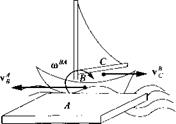
4.9 Captain’s relative motion. A boat В sails on rough water past the pier A. The linear velocity of its c. m. is v$ while its angular velocity is u>BA. The captain C is moving aft in the boat at the velocity vB. What is the velocity of the captain relative to an observer A on the pier?

Rotation tensor

4.10 Air passenger’s relative motion. A passenger P moves forward in the

cabin from point В at L m/s while the aircraft, cruising at constant speed [u£ ]B = [100 0 0] Ws, pitches up with 0(t) = 0q + 0.00It rad.

(a) Show that the velocity of the passenger wrt the Earth frame E is = Vp + SlBESPB + Vg.

(b) Calculate the numerical values of [uB]B and [uf]L if, initially, the two

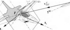
coordinate systems ]B and ]L are aligned with each other. (Solution: vE]B = [101 0 —0.001г] m/s.) 4.11 Intercept plane. As a missile intercepts an aircraft, its fuse fires near the airframe. To simplify matters, we define an intercept plane that is normal to the differential velocity vector v^r of the missile c. m. M wrt the target frame T and which contains the mass center T of the target. The miss distance of the missile is measured in this plane between T and M.

Derive the transformation matrix Tn of the intercept plane coordinates ]B wrt the target aircraft coordinates T using two methods.

(a) In the first method express the triadp|, p2, p3 of the intercept plane in ]r coordinates and thus construct [TH1. [vE1Tr and the target unit base vector f/3]7 are given in target coordinates. The intercept plane is oriented such that p, is parallel and in the direction of vTM andp2 lies in the t, t2 plane.

(b) The second method uses [i^J7 to calculate the polar angles i>pr, врт and derives T |7’7 from the two consecutive transformations ijfpj and Qpj. Calculate the numerical values of TH1 by both methods using [i)^rl7 [—500 100 100] m/s.

Подпись: A Rotation tensor

V/

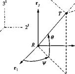
4.12 Line-of-sight rate kinematics. A radar station R tracks a point target T. The line-of-sight (LOS) displacement vector sTp is rotated from the radar’s triad ri, r2, r3 by the azimuth angle ф and the elevation angle в. We choose the inertial axes ]7 as the preferred coordinate system associated with the radar frame. For the LOS frame we define a coordinate system ]° in the following way: The 1°
direction is parallel and in the direction of Str’, the 3° direction is normal to str, lies in the plane subtended by r3, sTR, and for 0 < 0 <90 deg points toward r3.

Rotation tensor

(a) Derive the transformation matrix [T]01 of the LOS axes with respect to the inertial axes. Sketch the orange peel diagram.

(b) Derive the equation for the LOS rates u>0R that are based on the measured azimuth and elevation rates ф, 0 and express them in the inertial and LOS coordi­nates.

(c) Given the measured values if/ — 40 deg, 0 = 30 deg, and ф = 10 deg/s, в — 100 deg/s, calculate the numerical values for u>0R1 and [o/>R° (Solution: [ш™]’ = [64.27 -76.60 10], aP’° = [5.00 -100 8.66] deg/s).

4.13 Missile acceleration in LOS coordinates. For the formulation of an advanced guidance law, the inertial acceleration of the missile D7vj^ must be expressed in LOS coordinates d/df[u^]0. The guidance law generates the accel­eration command a’M, which through the autopilot results in the acceleration of the missile. For ideal autopilots D7vj^ = a’M. Provide the individual steps that lead to the desired relationship

These are first-order differential equations in v’M° with the commanded acceler­ation [афм in missile axes as inhomogeneous part. We have the following frames: M = missile, О = line of sight, and I — inertial and the preferred coordinate systems ]M, ]°, ];, respectively. Point M is the c. m. of the missile.

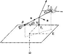
4.14 LOS rate. Flight simulators require the recording of angular LOS rates. The preferred components are 1) normal to the ground and 2) normal to the ver­tical plane containing the LOS. Given are the linear velocities of the missile and aircraft [uf ]L, _vR]L, respectively, and the LOS displacement [sBrL in local-level coordinates (north, east, down). Derive the equations for the angular LOS rates ш0Е and their components &>;3, parallel to the vertical unit vector/3 and oj„ parallel to the unit vector n, which is normal to the vertical LOS plane.

Rotation tensor

4.15 Rendezvous. The frames are the following: inertial I, Earth E, space shuttle B, and satellite S. The points are the following: location of Earth tracking station E, satellite c. m. S, and shuttle c. m. B. The coordinate systems are the following: Earth ]£, geographic ]G, and shuttle body axes ]B.

A space shuttle is sent to orbit to service a satellite. Before it can use its terminal docking radar, it must maneuver into the vicinity of the satellite. The crew uses the [Ssb]b and [vB]B displays in the cockpit to execute the approach. This position and velocity data are calculated by the onboard computer from [ssb]6, Lsbe]g, [uf ]G, and [i)g ]G that are recorded by the Earth tracking station. The orientation [ RB’B of the space shuttle wrt inertial space is determined by the onboard INS and the Earth’s orientation [f?£/]£ and transformation matrix TE0 provided by almanac tables. Your task is to develop the software that computes the displays [зд]я and [i>B]B.

Rotation tensor

(a) Obtain the tensor relationship for Ssb – For vB derive the result

vf = vf – vf + (DBR, BRiB – DER, ERiE)(sSE – sBE)

(b) Now derive the matrix equations for [.s,B]B and [uf]B, which are to be pro­grammed for the onboard computer. As a check, I give you the velocity equation

[vBs]B = [im*£¥m£G(k]G – k£f) + (mB[RBIiB

– [^]Bt^/]£[^£/]£[f? B/]B)[[«B/]B[^/]£[7’]£G(fe£]G – srtEG)]

4.16 Rotation tensor from rotation quaternion. Derive the rotation tensors [f? i] about the axis n ] = [10 0], given the rotation quaternion

cos(e/2)

sin(e/2)[n]

Do the same for [7?г] and [/?з] with [«2 І = [010] and [«3] = [00 1], respec­tively.

4.17 Rotation vector from rotation quaternion. Given is the quaternion {<?} = {q0 q1 q2 q3}. Provide the angle of rotation є and the components of the unit vector of rotation [n] = n n2 n3] as a function of the quaternion elements q0, qi, q2, and q2 only. Verify that the norm of n | is one.

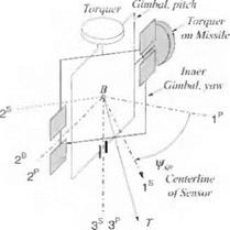
4.18 Seeker gimbal kinematics—project. When a missile comes within the acquisition range of the target, its antenna axis must be pointed at the target based on the onboard INS navigation information. Derive the equations for the seeker gimbal’s pitch and yaw angles, using the definitions displayed in the figure (the gimbal geometry is explained in more detail in Sec. 9.2.5).The INS provides the direction cosine matrix [T]BL and the LOS vector in local-level coordinates Lvb]l-

The definitions for the figure are as follows: body axes Is, 2B, 3s, outer gimbal axes 1B, 2P, 3P, inner gimbal axes Is, 2s, Зл, local-level axes ]L, yaw gimbal angle фsb, and pitch gimbal angle Osb ■

(a) Derive the equations for the seeker pointing angles Osb and фвв, which are to be programmed for the onboard computer.

(b) Given the Euler angles фвь =10 deg, ввь = 3 deg, фвь — 5 deg, and the target LOS vector [,syB] =[5 1 —3] km, calculate by hand the seeker pointing angles Osb and фвв in degrees.

(c) Program the equations for the seeker pointing angles in a subroutine INS POINT with the input arguments [T]BL and [лта]в and the output arguments 0Sb and фSB.

(d) Check your subroutine by enclosing it into a program and using the input values of (b).

(e) Use your subroutine for a second example: фвв = —30 deg, Obi, = —10 deg, фвь = — 20 deg and [swL = [2 — 1 —4] km and give the seeker pointing angles Osb and in degrees.

(f) Provide the source code listing.

Omtr

Rotation tensor

4.19 Target model—project. Missile simulations require target models of aircraft, cruise missiles, and even other missiles. These models do not have to be full six-DoF representations, but should exhibit the center of mass accelerations and the approximate attitude of the vehicle airframe. Your task is to develop such a target model and check it out in a simple three-DoF simulation.

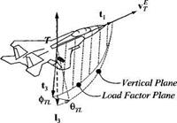
Positive Load Factor

Rotation tensor

You model the target by its frame T and its center of mass, point T. Its orientation is described by the transformation matrix TTL of the target coordinate axes wrt the local-level axes. You can introduce a simplification by aligning the first base vector of the target t with the velocity vector vf of the target T wrt to the Earth frame E. The third base vector E points in the opposite direction of the positive load factor. The two base vectors t and E span the loadfactor plane, while the local vertical h together with 11 define the vertical plane. Both planes are separated by the bank angle фті_. You calculate the transformation matrix TrL from the three Euler angle transformations: фц, eTL ■*- фп. (heading, flight-path angle, and bank angle). The location of the target is described by the displacement vector [лу/. ]L of the c. m. of the target T from an arbitrary reference point on the Earth E expressed in local coordinates.

Three inputs generate the target maneuvers: the combined drag and thrust ac­celeration axc, the load factor aN(., and the bank angle фть – To simulate the time lag of the target, these three input commands are delayed by first-order transfer functions with their respective time constants Tax, Tan, Тф.

(a) Derive the transformation matrix [T]TL. Write down the nine first-order differential equations that govern the target dynamics (three input states, velocity vector Vj]L, and location vector stel)- The target maneuvers in the maneuver plane, which differs from the load factor plane by the influence of the gravity vector. Derive the equations of the maneuver bank angle фмі., which is the angle between the projections of the total acceleration vector and l3 on the plane normal to t (between maneuver and vertical planes).

(b) Code the equations for the Module G1 of CAD AC or in another simulation environment. Use worksheets.

(c) Build your own test runs for five cases: 1) straight and level flight, 2) pla­nar climb, 3) horizontal 45-deg bank, 4) dive escape at 135-deg bank angle, and

5) launch of ballistic missile. You may also use staging (CADAC) to combine maneuvers.

(d) Document your results. Summarize the equations and add your worksheets and the code of Module G1 or your subroutine. Provide graphs of the five test cases.

Differential equations

The time derivative of the rotation quater­nion is buried in Eq. (4.75), but we have to transform the angular velocity quater­nion first to body coordinates—the body rates are given in body coordinates—and then solve for it. I will spare you the details, although the conversion is not diffi­cult, because the rotation tensor quaternion {QBE}L has its dual in the quaternion transformation matrix {Q}BL related by {QBE)L = [Q}BL. The result is

{QBE}L = -{DBE}B{QBE}L

Подпись: f/_o_ ~q Подпись: -[q] ЫЕ]~[й Подпись: UP... 2 I OJhe] Differential equations Подпись: -lq] qolE] - Q]

Partitioning the matrices

Differential equations

and equating the first partitioned columns

Подпись: 4o 1 4i 4i ' ~ 2 4 з. Подпись: -P 0 —r q Подпись: -q r 0 -P Differential equations Подпись: (4.77)

we finally obtain, with [соBE]B = [p q r], the desired differential equations

These differential equations are a joy to implement, because they are linear, have no singularities, and number only four. Yet, the initialization with Euler angles is not quite straightforward.

For initialization, we need to express the quaternion components in terms of Euler angles because who wants to describe the launch attitude of a missile in quaternions. Using Eq. (4.71) with Eq. (4.72) to build the three Euler rotations and

Differential equations Подпись: (4.78)

combining them q{jt)q(e)q((j>) leads to the relationships

Computational implementation of Eq. (4.77) must maintain the unit norm of the rotation quaternion even in the presence of rounding errors. A proven method is the addition of the factor k).[q to the right-hand side of Eq. (4.77) with к At < {(At integration interval) and к = 1 — (q^ + q + q + <y|) to maintain the unit norm.

The output of the differential equations must be converted to physical meaningful quantities. Those are primarily the Euler angles. Yet, rather than calculating them from the quaternion directly, we take the intermediate steps of rotation tensor and direction cosine matrix to obtain the Euler angles. By this approach we also make available the TM of body wrt local-level coordinates [T]BL.

. Rotation quaternion

The rotation quaternion has four coordinates q0, qi, q2, and q3 with direct relationship to the four Euler parameters n and є. In any coordinate system, with braces designating four-dimensional and brackets three-dimensional Euclidean space

Подпись: [q] = Подпись: q 42 43 Подпись: Sm|i Подпись: n 1 n2 «3

This relationship gives us a vivid picture of a rotation quaternion. The scalar component qo = cos(e/2) contains the half-angle of rotation, and the vector part

relates to the unit vector of rotation [и]. The mystery of four-dimensional space is explained if we consider the rotation quaternion consisting of a scalar part qo and

Подпись: 3L

2L

Fig. 4.16 Yaw rotation.

Подпись: {?} = Подпись: <?o я Подпись: (4.73)

a three-dimensional vector [q

A simple example may help your intuition.

Example 4.11 Rotation Quaternion

Problem. Body frame В is rotated wrt Earth frame E by the angle ф = 60 deg about the vector of rotation [n]L = [0 0 1] in local-level coordinates (see Fig. 4.16). Calculate the rotation quaternion {qBE}L.

Solution. Introducing local-level coordinates into Eq. (4.73) and with Eq. (4.72) provides

cos(i/r/2)

Подпись:Подпись: {qBE}Lsin(^/2)n!

sin(^/2)«2

sin(^/2)n3

Using the rotation vector and the numerical values of the example yields the rotation quaternion

cos(i/f/2)

0.5V3′

0

_

0

0

0

sin(i/f/2)«3

0.5

This is the rotation quaternion of the first Euler rotation about the angle yaw. The other two rotations about pitch and roll follow similar patterns.

4.3.3.2 Rotation tensor quaternion. As a vector has a skew-symmetric tensor equivalent, so does the rotation quaternion have a tensor equivalent. It

. Rotation quaternion

consists of the scalar part multiplied by the unit tensor quaternion and an additive skew-symmetric tensor quaternion

(4.75)

Подпись: [Q.BEt Подпись: d t . Rotation quaternion

Compare this definition with that of the three-dimensional space

Подпись: [Q.BE}L Подпись: 0 І [0)BE]L -[0)BE]L ; nBF:iL Подпись: (4.76)

The factor two of the quaternion definition grabs your attention, but is understand­able because quaternions operate with half angle of rotation. Because Eq. (4.75) involves rotation tensor quaternions, the angular velocity quaternion is also a tensor quaternion, yet without a scalar part

Not surprising, the vector part is the angular velocity vector of three-space.

We have assembled all required elements to proceed with the quaternial solution of the fundamental kinematic problem in flight simulations. Rearranging Eq. (4.75) will deliver the differential equations.

Quaternion Differential Equations

Would you believe that the introduction of quaternions preceded vectors and tensors? Sir W. R. Hamilton published in 1843 his quaternion algebra,5 which contained, albeit hidden, three-dimensional vectors.

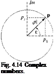
Quaternions are vectors in four-dimensional space, therefore their distinctive name. A simpler version, complex vectors, are their cousins in two dimensions. In Fig. 4.14 we consider the number 1 on the real axis as the first base vector and, on the imaginary axis, і as the second base vector. The two-dimensional vectorp can be expressed in the component form/? = l/?o + i/?i – With the angle of rotation e and absolute value | p known, we can also represent the complex variable in the polar form/? = реіє.

Подпись: Fig. 4.14 Complex numbers.

Now let us transition to four-dimensional space. We already encountered in Sec. 4.1.1 Euler’s theorem of rotation, which states that four parameters specify an arbitrary rigid rotation. There are three components for the axis of rotation n in addition to the angle of rotation e (see Fig. 4.15). Quaternions with unit norm represent such rotations in four-parameter space. Hamilton generalized the

1

Подпись: 3 Fig. 4.15 Euler’s four parameters.

two-dimensional complex number space by adding two more imaginary axes j and k. Embedded in this four-dimensional space is the rotation quaternion in the component form

q = qo+iqi + jqi + kq3 (4.71)

where ij = k, jk = i, ki = j and i2 = j2 = k2 — — 1 and its norm q% + q2 + q2 + q = 1.

Hamilton created a complete quaternion algebra with vectors as a special case. It is therefore not surprising that many concepts, which we have introduced in three- space, have their counterparts in four-space. To develop the quaternion differential equations, I shall make use of several entities. The rotation quaternion {q}, just introduced, the rotation tensor quaternion of frame В wrt frame E {QBE}, and the angular velocity quaternion of frame В wrt frame E The use of braces

identifies them as tensors in four-dimensional space, which, when coordinated, receive a superscript for the coordinate system.

Euler Angle Differential Equations

In days past, when computational efficiency was of prime concern, the direct integration of Euler angles was the preferred method. Let us investigate its merit and see why it has fallen from favor. We continue using the Earth as an inertial reference frame and the local-level coordinate system. Starting with the body rates [a>BE]B = [p q r], we develop the differential equations of the three Euler angles ф, в, and ф. A general solution can be derived from Eq. (4.66), but we use a simpler

Euler Angle Differential Equations

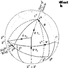
derivation based on the property that angular rates can be added vectorially. Figure 4.13 highlights the three Euler rates, which make up the body rates

шВЕ — фх3 + 0y2 + фу і

Selecting body coordinates

[coBE]B = ф[х3]в + Є[у2]в + ф[Уі]в and expressing the base vectors in their preferred coordinate systems

[x3]B = твхшх [y2]B – [T)BY[y2]Y [yif = mBYvyvf

yields the convenient expression of body rates

[a>BE]B = ф[Т]вх[х3]х + [Г]в;r(e[y2lY + <p[yilY)

With the TMs leading up to Eq. (3.14), we can coordinate the body rates

cos 0

0

—sin 0

"o

[coBE]B =

sinф sin#

COS Ф

sin ф cos 0

0

cos ф sin 0

—sin ф

COS Ф cos 0

Ф

‘l 0 o’

(

‘o’

+

0 cos ф sin Ф

в

+

0 —sin Ф COS Ф

0

Подпись: p —ф sin в + ф q — ф sin ф cos в + в cos ф r ф cos ф cos в — в sin Ф Подпись: 1 0 —sin в Ф 0 cos Ф sin</> COS в в 0 —sin ф cos ф cos в ф

Solving for the Euler angular rates yields the desired differential equations:

ф

sin 0 tan 0

cos ф tan в

Р

в

=

0

cos ф

—sin ф

q

ф

0

sin ф / cos в

cos ф / cos в

г

These three nonlinear differential equations, although compact and easily initial­ized, suffer from singularities at vertical climb and dive. Approaching these attitudes, the integration deteriorates and breaks down completely at the singu­larities. Only in older simulations will you still find these equations. They are used by the CADAC FALCON6 simulation. With modem, high-performance computers the old requirement for computational efficiency has given way to accuracy and flexibility. In its train was swept in the ancient quaternion to slove the fundamental kinematic problem. We revive it for the third method.