Category Modeling and Simulation of Aerospace Vehicle Dynamics

Rotation Tensor Differential Equations

The first approach is based on the definition of the angular velocity tensor, Eq. (4.47) referenced to body frame B. If expressed in body coordinates, the rotational derivative reduces to the ordinary time derivative [see Eq. (4.37)]:

Подпись: п/ВтВг піВлВRotation Tensor Differential Equations[£2,B]B = [£>вЯ7в]в[Я/в]

Solving for the time derivative

Подпись: В[dRIB~

Rotation Tensor Differential Equations

d t

produces the differential equations for the nine elements of the rotation tensor.

In simulations, rather than calculating the rotation tensor, the focus is on the TM of body wrt inertial coordinates. The connection is provided by Eq. (4.6), | T]111 = [RBI]B, which we can apply directly to Eq. (4.64):

Подпись: dT dt bi _____

= (4.66)

These are the famous differential equations of the direction cosine matrix. You will see them again in Sec. 10.1.2 when we formulate the six-DoF equations of motion over an elliptical Earth. In simpler simulations, when Earth E serves as an inertial frame, the local-level system is used. Therefore, we replace frame / by E:

Подпись: dr dt bl _____

= [£2№]В[Г]“- (4.67)

where [T]BL relates to the Euler angles of Eq. (3.28). If the Euler angles are given at launch, use Eq. (3.28 ) to initialize the nine elements.

The nine differential equations are not independent. Because the TM is com­posed of three orthonormal base vectors, only six differential equations need be solved, and the remaining three elements can be calculated from the orthogonal­ity conditions. Express the direction cosine matrix in the three base vectors of the geographic frame [T]BG = [[gj]B [#2ІЙ and substitute them into the

differential equation, Eq. (4.67),

£[[ЫВ Шв Ыв] = [^]*[[gi]B шв ыв]

Take the first two columns individually, add an orthogonality condition, and you have the set of six differential and three algebraic equations:

^[gi]B = [^]B[g!]B

ck

^[g2]B = [^]B[g2]B (4.68)

ck

Шв = [Gi]B[g2]B

To recover the Euler angles, use Eqs. (3.15-3.17) or an alternate form that is used in flight simulators:

Подпись: ф = arccos

Rotation Tensor Differential Equations

(4.69)

where the tij are the elements of the direction cosine matrix. Equation (4.69) de­livers similar results as Eqs. (3.15-3.17). The sign function—FORTRAN intrinsic function SIGN(A, B)—controls the sign like the FORTRAN ATAN2(A, B) function in Eqs. (3.15-3.17). The range of the angles is — ж < ф < +n, —ж < ф < +ж, and —ж/2 < в < +ж/2.

With these types of Euler angles adopted for flight mechanics, singularities oc­cur at в = ±jt/2, where no distinction is possible between yaw and roll. These correspond to a vertical dive or climb, situations seldom encountered in airplanes, but important in missile launches. Resequencing the Euler angles can place the singularity at another less conspicuous attitude. Fortunately, this undesirable be­havior occurs only in the output calculations and not in the differential equations themselves, where they would provoke much more trouble.

Integrating the differential equations on digital computers with finite word length and incremental time steps produces errors that corrupt the TM. To maintain or­thogonality, a correction term is applied from integration step n to n – f – 1:

[T(n + l)]s/ = [Т(п)]ш + ([E] – [T(n)]BI[T(n)]B!)[T(n)]BI

As a sanity check, note that the correction term is zero for orthogonal TMs. For details however you have to wait until Sec. 10.1.2, which describes the implemen­tation as part of a six-DoF simulation. The actual code can be found in the CADAC GHAME6 simulation.

The rotation tensor and direction cosine matrix solutions have superior features that lend themselves to computer applications. The differential equations are linear, well behaved, and without singularities. Above all, the important direction cosine matrix is directly computed. However, because Euler angles are so much easier to visualize, initialization and output have to be converted. To avoid this conversion, the Euler angles can be integrated directly.

Attitude Determination

A final subject of importance is the fundamental problem of kinematics of flight vehicles. In six-degree-of-freedom (DoF) simulations the application of Euler’s law renders the differential equations of body rates. More precisely, the solution of the differential equations yields the angular velocity vector of the vehicle frame В wrt the inertial frame I, expressed in body coordinates [wBI]B. Specialists call them the p, q, r components of

[coBIf = [p q r]

The fundamental problem states as follows: Given the body rates [coBI]B, deter­mine the orientation of the vehicle wrt the inertial frame. The orientation can be expressed in terms of the rotation tensor, Euler angles, or quaternion. Because ori­entation is removed from angular velocity by integration, the solution will embody differential equations. I shall treat each of the three possibilities individually.

Properties of angular velocities

The angular velocity tensor and vector have additive properties. Their superscripts reveal the rotational direction, and they relate to coordinate transformations in a special way.

Property 1

Angular velocities are additive. For example, if frame В revolves relative to frame A with ttBA and frame C wrt frame В with flCfl, then C revolves wrt A with the angular velocity tensor

Подпись: ПСА = ПСВ + nBA (4.58)

The vector equivalent is

(4.59)

The superscripts reflect the sequence of addition. By contracting adjacent letters, you get the result on the left-hand side.

Proof: Apply the Euler transformation twice to an arbitrary vector x Da x = DB x + ПВАх – DB x = Dcx + Псвх and substitute the second into the first equation:

Da x = Dc x + Псвх + ПВАх = Dc x + (Псв + ПВА)х Compare this result with a third application of Euler’s transformation

Da x = Dcx + ПСАх and conclude: flCA = flCft + ПВА.

Property 2

Reversing the sequence between two frames changes the sign of the angular velocity tensor:

Подпись: (4.60)nBA = – nAB

Properties of angular velocities Properties of angular velocities Подпись: (4.61)

The vector equivalent is

Proof: Replace C by A in Eq. (4.58) and, because flAA = 0, the relationship is proven. The angular velocity vector equivalent follows by contraction.

Property 3

The rotational time derivative of the angular velocity vector between two frames can be referred to either frame

Daujba = Dbuba (4.62)

Proof: Transform the rotational time derivative of шВА from frame A to В,
Daujha = Dbujba + ПВАшВА

and recognize that the last term, being the vector product of the same vector, is zero.

Подпись: г йшВАл At Properties of angular velocities Подпись: dcoBA At

Note that Eq. (4.62) also holds for regular time derivatives expressed in the associated coordinate systems ]A and ]B:

Proof: From Eq. (4.62)

[Dacoba]a = [T]ab[Dbcoba]b

Properties of angular velocities

which proves the relationship.

Property 4

Подпись: dr d t Properties of angular velocities Properties of angular velocities Подпись: AT At Подпись: BA Подпись: (4.63)

The coordinated angular velocity can be calculated from the coordinate trans­formations of the associated coordinate systems:

Properties of angular velocities Properties of angular velocities

Proof: From the definition of the angular velocity tensor, Eq. (4.47) expressed in the associated coordinate system ]A and because of Eq. (4.6) we form

Подпись: [T]BA[Q.bA}A[TYA = [Tf Подпись: AT At Properties of angular velocities

The second part is proven by transforming to the ]B coordinate system

Example 4.10 Turbojet Spooling

Problem. A pilot increases thrust as he pulls up the aircraft. The turbine’s Г angular velocity [coTA]A wrt the airframe A is recorded in airframe coordinates l’1, and the aircraft pitch-up rate coAEL wrt Earth E is measured by the onboard INS in local-level coordinates ]L . Both angular velocities are changing in time. Determine the angular acceleration of the turbine [АшТЕ/At]1 wrt Earth in local – level coordinates. The INS provides also the direction cosine matrix [ T |’u.

Solution. The solution follows the two-step approach: Solve the problem in tensor form, followed by coordination. We use the additive property of angular ve­locities then apply the rotational derivative wrt Earth and the Euler transformation to recover the turbine revolutions-per-minute measurement. Then we introduce the appropriate coordinate systems to present the turbine acceleration in local-level coordinates.

The angular velocity of the turbine wrt Earth is

Take the rotational derivative wrt Earth

Deute = Deuta + DeuAe

Transform the turbine derivative DEwTA to the airframe A and obtain DEuTE = DAuTA + Оаешта + Deljae

Introduce local-level coordinates

Подпись: . AE-L[DEa)TE]L = [DAa)TA]L + [QAEf[coTA]L + [DEa, AE]L

Because the local-level coordinate system is associated with the Earth frame, the first and last rotational derivative simplify to the ordinary time derivative. The second rotational derivative, as well as the turbine speed, must be transformed to the airframe axis to get the desired result:

Г rmTE 1

L

d coTA

A

Г dcuA£"|

= [T]AL

+ [Q. AEf[T]AL[ioTA]A +

dt

dt

dt

As you see, you cannot just add together the angular accelerations. The turbine speed also couples with the aircraft angular rate as an additional acceleration term.

Sections 4.1 and 4.2 that you have just mastered are the trailblazers for invariant modeling. Particularly, the rotational time derivative and the Euler transformation preserve the tensor characteristics of kinematics, even under time-dependent co­ordinate transformations. To adopt them as your own, and apply them whenever the opportunity arises, should become your ambition. I have put them to good use for 30 years, and they spared me some major headaches.

Euler Transformation

The rotational time derivative is the pass key to the invariant formulation of time – phased dynamic systems. As an operator that preserves the tensor characteristic, it depends on a reference frame. Sometimes it is desirable to change this reference frame, for instance from inertial to body frame. Euler’s generalized transformation governs that change of frame.

We approach the derivation of this vital transformation fastidiously in increasing complexity. An ad hoc introduction points to the possible formulation, followed by a heuristic derivation based on the isotropy of space. The eggheads among you are referred to Appendix D, which provides an analytical proof.

Euler Transformation Euler Transformation

The classical Euler transformation is embodied in Eq. (4.34). It transforms the time derivative from frame A to frame B. Comparison with Eq. (4.35) leads to the conjecture that

Подпись: ds At Euler Transformation Подпись: d.s At

so that the last term of Eq. (4.35) reflects the vector product [f2BA]B[s]B

Introducing the rotational time derivatives for the two special cases [ds/dt]A = [Dasa and [d. s/dtjft = [DBs]B, we can formulate

[DA5]A = [T]ab([Dbs]b + [£2BA]B[s]B)

The key question is whether this transformation is a tensor concept. As written, it holds only for the associated coordinate systems ]A and Jft. Fortuitously, it can be generalized for any allowable coordinate system. We call it Euler’s general transformation, or just plain Euler transformation.

Theorem: Let A and В be two arbitrary frames related by the angular velocity tensor ПВА. Then, for any vector x the following transformation of the rotational time derivatives holds:

Dax = DBx + ElBAx (4.51)

Proof: The theorem is a direct consequence of the isotropic property of space. lt’ReA is the rotation tensor of frame В wrt frame A, then, because of the isotropic property of space, the rotational derivative of x wrt frame A, DAx can also be evaluated as follows:

1) First rotate x through RBA to obtain Rbax.

2) Take the rotational time derivative wrt the rotated frame, now called B, Db{RBAx).

3) Rotate the result back through RBA into the original orientation. The three steps produce

DAx = RbaDb(Rbax)

The chain rule applied to the right side yields

Da x = DB x + RbaDbRbax (4.52)

If we can show that RBADBRBA = CtBA, the theorem is proved. Let us interchange A and В and execute the same three steps again:

DB x = Dax + RabDaRabx

Adding the last two equations provides

RBADBRBA = – RABDARAB (4.53)

The right-hand side is the desired fl, M because the transpose changes the order of rotation

—RABDARAB = —RbaDaRba = —DaRbaRba and recall the definition of the angular velocity tensor, Eq. (4.47), where

-DARBA~RBA = – ftBA = ftBA

Therefore, Eq. (4.53) is ttBA and indeed Eq. (4.52) proves the theorem:

Подпись: QEDDa x = DBx + ПВАх

With the Euler transformation at our disposal, we can model many interest­ing kinematic phenomena. First, let us have another look at linear velocities and accelerations and then state and prove several properties of angular velocity and acceleration.

Example 4.8 Relative Velocities

Problem. Refer back to Example 4.6 and Fig. 4.10. Let us assume that the radar lost track of the target, but still receives the missile’s measured target velocity Vj via data link while tracking the missile’s velocity vBr. What is the velocity of the target wrt the radar vB, and how can it be calculated?

Solution. All three quantities are relative velocities. It is tempting to add them vectorially vB = Vj +v", but this is only possible if both the missile and the target were modeled by points only. However, the seeker is measuring the target velocity v" wrt the missile reference frame M. Therefore, the angular velocity of the missile relative to the radar frame enters the calculation. I will derive the proper equation from the basic displacement triangle, employing the rotational time derivative and Euler transformation.

From Fig. 4.10,

Str = Stm +Smr

We impose the rotational time derivative to create the desired relative velocity vR – Drstr

DrStr = DrStm + DrSmr (4.54)

The differential velocity DrStm = vtm is unavailable. Instead, the missile seeker measures Vj = DmStm – The kinship is provided by Euler’s transformation

DrStm — DmStm + nMRsTM

Substituting back into Eq. (4.54) yields an equation, exclusively with relative velocities:

vR = v?+ nMRsTM + V* (4.55)

To implement this equation in the radar processor, we need to know the coordinate system of the measured data. The target velocity is measured in missile coordinates VjM ; the angular velocity tensor, recorded by the onboard INS, is beamed down in radar coordinates QMRR (the R frame is also the reference frame of the INS); and finally, missile position and velocity are measured by the radar in its own coordinates smrr and | ]л. Because ]й is prevalent, we coordinate Eq. (4.55)

first in radar coordinates

followed by transforming the target velocity into missile coordinates

[vr]r = [TfM [<f + [П"*]*[*ш]* + [u*f (4.56)

We have succeeded in deriving the component equation for implementation, pro­vided the coordinate transformation [T]RM from the missile INS is also beamed down to the radar station.

Example 4.9 Relative Accelerations

Problem. Continuing with the Example 4.8, we ask how to calculate the target’s acceleration wrt the radar aR when it is measured by the missile a’j 1

Solution. We start by taking the rotational time derivative wrt frame R of Eq. (4.55) to obtain the desired acceleration aR = DRvR:

Drv$ = Drv¥ + DR(nMRsTM) + DRv% (4.57)

Let us discuss the right-hand terms one at a time.

1) The first term DrVj relates to two different frames. To change it into the desired target/missile acceleration a’j = DMvf, we need to apply the Euler transformation

= DMvf + nMRv%! = a% + ftMRv"

2) The second term Dr($ImrStm) is converted by the chain rule and the Euler transformation to obtain v™:

DR(nMRsTM) = DRnMRs tm + nMRDRs TM = DRnMRsm + nMR(DMsTM + nMRsTM) = DRnMRsrM + nMRv¥ + nMRnMRsTM

The right side consists of the angular acceleration term, one-half of the Coriolis acceleration, and the centrifugal acceleration.

3) Подпись: radar DRv^ = a

Подпись: ,R M-

The third term DRvfj is the easy one. It is the missile acceleration wrt the

Euler Transformation

Collecting terms, Eq. (4.57) expresses the target acceleration in known quanti­ties:

What a formidable equation to implement! If we only could model the missile by a simple point, then ttMR would not exist, and the target acceleration would simply be

This shortcut is made frequently. But do not forget to assess the neglected terms.

These two examples should give you the working knowledge for modeling linear velocity and acceleration problems. We now turn to angular velocities and accelerations. Refer back to Sec. 4.2.3 and recall the definition of the angular velocity tensor Eq. (4.47). Do not forget that it is a skew-symmetric tensor and therefore contracts to an angular velocity vector. With our freshly acquired Euler transformation we are able to prove several properties of angular velocity.

Angular Velocity

As the linear velocity is bom of the displacement vector, so is the angular velocity derived from the rotation tensor by the rotational time derivative. We take a two-track approach. To pay homage to vector mechanics, I present the classical approach to be found in any mechanics text like Goldstein,1 and the general development via the rotational time derivative.

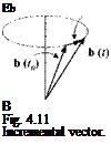
4.2.3.1 Classical Approach. Consider a vector b of constant magnitude rotating about its fixed base point В (see Fig. 4.11). At time t it is displaced from its original position at time Го by

eb = b(t) — b(to)

The time rate of change of eb is the tip velocity v, formed from the limit as At —> 0:

Angular Velocityb(t) – b(t0) d(sb)

Substitute Eq. (4.25) into this equation:

Подпись: (0

Подпись: Eb В Fig. 4.11 Incremental vector.

(4.45)

Angular Velocity

b(0

Because єЬ is small, sR and consequently [d(ef?)/dr] are skew-symmetric tensors (see Sec. 4.1.4). Therefore, Eq. (4.45) presents the vector product of the classical form v = ш x b(t{}) with ш as the angular velocity.

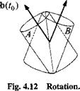
4.2.3.2 General development. Introduce frame A associated with the con­stant b(to) and frame В associated with b(t) (see Fig. 4.12). The two vectors are related by the rotation tensor RBA of the frame В wrt frame A

b(t) = RBAb(t0) (4.46)

To determine the tip velocity of b(t), take the rotational derivative wrt frame A and apply Eq. (4.46) twice:

vA = DAb(t) = DARBAb(t0) = DARBARBAb(t)

We define the angular velocity tensor of frame В wrt frame A as

Пм = DaRbaRba (4.47)

and obtain the tip velocity

Vg = nBAb(t) (4.48)

Comparing Eqs. (4.45) and (4.48) and assuming small displacements 6(r0) ~ b(t), we can relate the time derivative of the perturbation tensor of rotation with the angular velocity tensor

Подпись:d t

and conclude that because eR is skew symmetric then so is QBA. The angular velocity tensor possesses, therefore, the vector equivalent шВА. For any coordinate system, say ]c, we have the following correspondence:

Подпись:(4.50)

Let us solidify the fact that the angular velocity tensor is skew symmetric.

Proof: Show that the angular velocity tensor is skew symmetric.

Start with the null tensor and develop the result:

0 = — E = DA(RBARBA) = DARBARBA + RbaDaRba = ПВА + ПВА at

Therefore, fiBA = —fiBA and ttBA is skew symmetric.

The nomenclature of angular velocity abides by our standards. As indicated, only frames determine its definition, and the superscripts are read from left to right, e. g., fiBA is the angular velocity tensor of frame В wrt frame A. Section 4.2.4 discusses additive properties and other characteristics, which can only be proven after the introduction of the Euler transformation.

Example 4.7 Missile Separating from an Aircraft

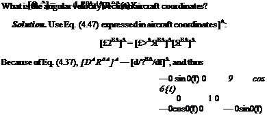
Problem. A missile В separates from an aircraft A and descends in the vertical plane. The rotation tensor in aircraft coordinates is given by

Подпись: cos 9(t) 0 sin 6{t) 0 1 0 sin 9(t) 0 cos 0(f)

Angular Velocity

A

At

cos 0(f)

0

—sin0(f)

0

0

0"

X

0

1

0

=

0

0

0

sin0(f)

0

cos 0(f)

-0

0

0

and the angular velocity vector is [®BA]A = [0 9 0].

We have added several new concepts to our collection while remaining true to our hypothesis that any phenomena in flight dynamics can be modeled solely by points and frames. Let us review. Displacement Sba uses only points, whereas rotations Rba use only frames. Linear velocities vA} and accelerations aj, mix it up, whereas angular velocities uBA employ only frames. Finally, the rotational time
derivative refers to frames only. Changing its reference frames is the subject of the next section.

Linear Velocity and Acceleration

At several occasions we have encountered already the linear velocity v j) of point В wrt frame A. Now we have to assign it a definition (refer to Fig. 4.9). Given

Linear Velocity and Acceleration

Linear Velocity and Acceleration

Fig. 4.9 Linear velocity.


is the frame A and the displacement vector sBA, where В is any point and A is a point of frame A. The linear velocity of point В wrt frame A is obtained from the rotational time derivative wrt frame A, applied to the displacement vector sBA:

vAB = Dasba (4.40)

The notation of the linear velocity vector does not carry over the identity of point A, but just refers to the frame A. This simplification is justified by the fact that any point of frame A can serve as reference point.

Proof: Show that the point A in Eq. (4.40) can be any point of frame A. Let A1 and A2 be any two points of frame A. Then sBA = sBA2 + sA2A. Take the rotational time derivative on both sides and use the second part of Property 1:

DASba 1 — DASBA 2 + DASA2Al

However, DasA2A — 0 because the displacement vector s,2a i is fixed in frame A. Therefore,

Dasba 1 = Dasba2 – vB

The fact that DasA2Ai = 0 can be verified from Eq. (4.36). Pick ]A as a coordinate system associated with frame A. Then

dSA2Al

A

[dTl

d t

+ [T]

_ ^ _

_DASA 2Ai]

[Sa2Ai]a.

Both terms are zero. The first term is an ordinary time derivative of a vector with constant length, and the second term takes the time derivative of a unit matrix. If a tensor is zero in one coordinate system, it is zero in all coordinate systems.

Example 4.6 Differential Velocity

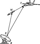
Problem. A missile with c. m. M is attacking a target, point T (see Fig. 4.10). Both are tracked by the point antenna R of the radar frame R. What is the velocity of the target wrt the missile as observed from the radar?

Solution. The displacement vector of the target wrt to the missile is

Linear Velocity and Acceleration

Fig. 4.10 Differential velocity.


We take the rotational derivative wrt the radar frame R and apply the linear operator property

DrStm = Dr(str — sMr) — DrStr — DrsMr

According to the linear velocity definition Eq. (4.40), the right-hand sides are DrStr — and DrSmr = vRM. The term on the left however is different. None of its points belongs to the radar frame. Rather the two points relate the target to the missile. Its rotational derivative wrt to the radar frame forms the desired velocity. We name it the differential velocity of T wrt M as observed from frame R and write

Linear Velocity and Acceleration(4.42)

The concept of differential velocity is particularly important in missile engage­ments and will surface again in our discussion of proportional navigation.

In this example we encounter two types of linear velocities distinguishable by their reference points. If the reference point is part of the reference frame, we speak of the relative velocity, or just velocity (e. g., vR) otherwise, if the reference point is not part of the reference frame, we refer to it as differential velocity (e. g., vRM).

Linear Velocity and Acceleration Подпись: (4.43)

The linear acceleration aAB of a point В wrt the reference frame A is defined as the second rotational derivative of the displacement vector sBA, or the first derivative of the velocity vector

If the reference point A is part of the reference frame A, any point of that frame can be used, and thus the nomenclature aB does not explicitly identify the reference point A. (It may be beneficial at this point to remind you that without exception points are subscripts and frames are superscripts.) This type of acceleration, relative to reference frame A, is also called relative acceleration to distinguish it from the differential acceleration.

Referring to Fig. 4.10, the concept of differential acceleration is similar to differential velocity. If we take the second rotational derivative of the displacement

vector Eq. (4.41), we obtain

DrDrStm = DrDrStr — DrDrsMr

On the right-hand side the reference point R is part of the reference frame R, and therefore the two terms are the relative accelerations DrDrSjr — aR and DR DRsMR=allt. The term on the left contains the reference points T and M that do not belong to frame R. Hence, we are dealing with the differential acceleration Dr DrStm = ar. M’ which is the difference of the two relative accelerations

Подпись: (4.44)атм — ат ам

Linear velocities and accelerations are important building blocks in any simula­tions. You will have ample opportunity to use them as modeling tools of aerospace vehicles. Yet our toolbox is incomplete without the angular velocities and accel­erations.

Rotational Time Derivative

The challenge is to find the time operator that preserves the form on both sides of Eq. (4.35). We venture to define the terms in parentheses as that operator and see what happens to the left side.

Definition: The rotational time derivative of a first-order tensor x wrt any

Подпись: [DAX]B = Подпись: dx d t Подпись: + [T]BA Подпись: d T d t Подпись: [x] Подпись: (4.36)

frame A, DAx, and expressed in any allowable coordinate system ]B is defined by

Notice in [Dax]b the appearance of frame A and coordinate system ]B. Both are arbitrary, but the coordinate system ]4 of [T]BA on the right-hand side has to be associated with frame A.

Let us break the suspense and apply the rotational derivative to the left side of Eq. (4.35). Instead of ]B the coordinate system is now ]4:

ds

A

l-dTl

-AA

ds

+ [T]AA

– dt _

=

_d t _

_dt _

[Das]a =

which is, with the time derivative of the unit matrix being zero, exactly in the desired form. Therefore, we can write Eq. (4.35) as

[Das]a = [T]ab[Das]b

Rotational Time Derivative Rotational Time Derivative Подпись: ГА “|S QS d t Rotational Time Derivative Rotational Time Derivative

That looks to me like a tensor transformation. Although the ]B coordinate system is arbitrary, the ]A system is still unique by its association with frame A. For a true tensor form any allowable coordinate system must be admitted. Therefore, consider an arbitrary allowable coordinate system ]Dto replace ]Aon the left side of Eq. (4.35):

By definition of the rotational derivative, we obtain the true tensor transformation

[Das]d = [T]db[Das]b

Therefore, the rotational derivative of a vector transforms like a tensor, and DAs

is a tensor.

A comparable rationale defines the rotational derivative for second-order ten­sors. I will just state the results. The details can be found in Appendix D.

Definition: The rotational time derivative of a second-order tensor X wrt any

Подпись: [.DAX]B = Подпись: dX d t Rotational Time Derivative Rotational Time Derivative Подпись: dT df Rotational Time Derivative Подпись: (4.37)

frame A, DAX, and expressed in any allowable coordinate system ]B, is defined as

We have two terms pre – or postmultiplying the tensor with the term [T]BA [dr /dt] and its transpose.

The rotational derivative of tensors transforms like a second-order tensor. For any two allowable coordinate systems ]B and ]D,

[.DaX]d = [T]db[DaX]b[T]db

Therefore if X is a second-order tensor, so is DAX.

The rotational time derivative has some nice properties that will make it a joy to work with.

Property 1

The rotational derivative wrt any frame A is a linear operator. 1) For any constant scalar к and vector*

DA(kx) = kDAx

(4.38)

2) For any two vectors x and у

DA(x+y) = DAx + DAy

(4.39)

Property 2

The rotational time derivative abides by the chain rule. For any tensor Y and vector x

Da(Yx) = (DaY)x + YDax

Note that you must maintain the order of the tensor multiplication. The parenthe­ses on the right side are redundant because, by convention, the derivative operates only on the adjacent variable.

The rotational derivative strengthens the modeling process of aerospace vehicles. It enables the formulation of Newton’s and Euler’s laws as invariants under time – dependent coordinate transformations. As you will see in Chapters 5 and 6, we remain true to our principle from tensor formulation to matrix coding. With the instrument of an invariant time operator in hand, we can create linear and angular velocities and their accelerations.

Kinematics of Changing Times

We are now prepared to invite time into our Euclidean three-dimensional world and develop the tools to study the kinematics of motions. Motions are modeled by including time dependency in the displacement vector and the rotation tensor. Hence, if sBa is the displacement vector of point В wrt point A, Sba(0 describes the motion of point В wrt reference point A. Likewise, RBA(t) models the changing orientation of frame В wrt the reference frame A.

Other kinematic concepts are formed by the time rate of change of displacement and rotation. Linear velocity is the first and acceleration the second time derivative of displacement. Angular velocity is obtained by the time derivative of rotation. For instance, the linear velocity of point В wrt frame A is produced by vAH = (d/dt)«AB – Yet these new entities require close scrutiny if we want them to be tensors. Remember, physical models, like velocity, maintain their tensor property only if their structure remains invariant under coordinate transformations. As long as the coordinate transformations are time invariant, the time derivative does not change the tensor characteristic of its operand, but our modeling strategy is more ambitious. We require that the time derivatives of tensors are tensors in themselves, even under time-dependent coordinate transformations.

Kinematics of Changing Times Подпись: ds — +ЫХ! d t в Подпись: (4.34)

Pick up any textbook on mechanics and you find the following treatment of the time derivative of vector s transformed from A to В coordinate system:

where ш is the angular velocity between В and A. Unfortunately, the right side has an additional term, and thus the time derivative destroyed the tensor property of the derivative of vector s.

Let us translate Eq. (4.34) into our nomenclature. With any two allowable co­ordinate systems J’4 and ]B the vector s transforms like a first-order tensor:

[S]A =

Подпись: ds d t Kinematics of Changing Times Kinematics of Changing Times

Taking the time derivative and applying the chain rule

Подпись: rds~lA d t Kinematics of Changing Times Подпись: ds dr Kinematics of Changing Times Kinematics of Changing Times Подпись: (4.35)

and exchanging the sequence of transformation in the last term by transposition yields

Comparison with Eq. (4.34) shows that the right and left sides are related by the TM [T]AB and that the ш vector corresponds to the term |T |/M [dT/dt]B’4.

From Eq. (4.35) it is clear that the time derivative of s does not transform like a first-order tensor. If, however, we could define a time operator that would give the right and left side the same form, the tensor property would be maintained. Does such an operator exist? Indeed it does, and it is called the rotational time derivative.

Back in 1968, pursuing my doctoral dissertation, I found in Wrede’s book2 on vector and tensor analysis just the concept I needed. He defines a rotational time derivative, whose operation on tensors preserves their tensor property. It is couched in hard-to-understand tensor lingo; but applied to right-handed Cartesian coordinate systems, the concept is easy to grasp. Later I discovered that Wrede’s work was preceded by Wundheiler’s (Warsaw, Poland) research, in 1932.3

Small Rotations

Isn’t it interesting that the orientation between two frames, although determined by unit vector and angle, requires a second-order rotation tensor for portrayal? If several rotations are combined, the sequence is not arbitrary because the multipli­cation of second-order tensors does not commute. Both attributes are simplified, however, if we deal with so-called small rotations. Small rotations reduce to vectors and can be combined in any order.

Engineers like to deal with small quantities. They are so much easier to model because the mathematics is simpler. Consider the stability equations of aircraft with their implicit small angle assumption and the error equations of INS systems. These small perturbations simplify the analysis, resulting in linear differential equations, the darlings of engineering analysis.

єЬ

b(t0)

er

Fig. 4.8 Small rotation.

I will guide you from the general rotation tensor to the perturbation tensor of rotation, the small rotation vector, and finally, the small rotation tensor. All of these concepts are important and should be in your toolbox. We will start with the question: what is the form of the rotation tensor if a vector is rotated by an infinitesimal small amount?

Rotate vector b from its initial position b(to) through rotation tensor R to its current position

b(t) = Rb(t0) (4.22)

The difference eb between the two vectors is, as shown in Fig. 4.8, sb = b(t)—b(t0) and with Eq. (4.22)

eb = (R — E)b(to)

(4-23)

Introducing the definition of the perturbation tensor of rotation

eR = R – E

(4.24)

into Eq. (4.23) yields

eb = eRb(t0)

(4.25)

The displacement vector eb is the result of the multiplication of a tensor eR with the initial vector. What is the property of this tensor?

Because R is orthogonal, RR = E, and from Eq. (4.24)

E = (eR + E)(eR + E) = E + eR + eR + eReR

Now we assume that є indicates a small quantity. Then the last term is small to the second-order wrt the other terms and can be neglected. Thus eR = —eR, i. e., the perturbation tensor eR is skew-symmetric and thus can be represented by a vector. For any allowable coordinate system |-4 the perturbation tensor has the components

ern

ЄГ12

er 13

ЄГ21

ЄГ22

ЄГ23

ЄГ31

ЄГ32

ЄГ33

Small Rotations Подпись: (4.26)

but if it is skew-symmetric it has only three independent components,

Подпись:(4.27)

Finally, the tensor R for small rotations consists according to Eq. (4.24) of the unit tensor and the perturbation tensor Eq. (4.26). Expressed in any allowable coordinate system A, it becomes

Подпись:(4.28)

By now you may be thoroughly perturbed by all of these perturbations. Let us recap. The rotation tensor of a small rotation between two frames, say В wrt A, Rba, consists of the unit tensor E and the perturbation tensor of rotation sRBA

RBA = E + sRba

where sRba can be reduced to a small rotation vector er. To clarify these concepts, let us look at an example.

Example 4.5 INS Tilt

An INS maintains a level reference either by a gimbaled platform or a computed reference frame. Yet, mechanical or computational imperfections cause the refer­ence to deviate from the true values. These errors, called tilts, are rather small and are measured in arc seconds.

The tilt angle в (pitch) of an INS platform about the east direction gives rise to the rotation tensor expressed in geographic axes ]G

Подпись: 0 sin в 1 0 0 cos в Подпись: COS в 0 —sin0 [Rtf)]0 =

Because the tilt is a very small angle єв, we introduce the small angle assumption

Подпись: 1 0 єв 0 1 0 —єв 0 1 r of rotation is 0 0 єв 0 0 0 —єв 0 0 Подпись:(4.29)

with the corresponding small rotation vector [ег(єв)]в = [0 єв 0]. Similar small rotation tensors can be developed for the tilt ф about the north direction and the azimuth error ф:

‘l

0

0

‘ 1

—еф

0

[tf(e0)]G =

0

1

—еф

; тєф)]° =

еф

1

0

0

еф

1

0

0

1

The complete tilt tensor consists of the product

Подпись:[Я(еф, ев, еф)]с = [Я(є0)]с[Л(є0)]о[Я(еіА)]с

and the multiplications carried out

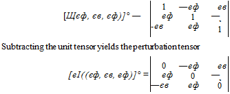
Подпись:(4.31)

(4.32) from which we obtain by analogy with Eqs. (4.26) and (4.27) the small rotation vector

[єг{еф, ев, еф)]° = [еф єв еф] (4.33)

Here you experienced all three notions: small rotation tensor, perturbation tensor of rotation, and small rotation vector. You can convince yourself of the commu­tative property of small rotations by changing the sequence of multiplication in Eq. (4.30) and each time arriving at the same result Eq. (4.31)

This insight into perturbations prepares you to follow the derivation of an INS error model in Sec. 10.2.4, which is used in six-DoF simulations. The tilt tensor, with its tilt vector, models three of the nine INS error states. Another application of importance is the derivation of the perturbation equations of air vehicles, Sec. 7.2. You will find again a small rotation tensor describing the deviation of the perturbed flight from the reference flight.

We have about exhausted the topic of rotation tensors. As the displacement vector models the location of point В wrt point A, so does the rotation tensor establish the orientation of frame В wrt frame A. Both together define the position of frame В wrt frame A (refer to Sec. 3.1.1). We established the tensor characteristic of rotations and the special circumstances under which they relate to transformation matrices. You should by now be convinced that both are different entities! We dealt with special rotations like the tetragonal symmetry tensor and small rotations. A correct understanding of these concepts will make it easier for you to grasp the following kinematic developments.

Axis and Angle of Rotation

You have learned that a rotation tensor is orthogonal with the determinant value + 1. Conversely, every orthogonal 3×3 tensor with determinant +1 represents a rigid right-handed rotation. Given such a rotation tensor, how do we calculate its rotation axis and rotation angle?

4.1.3.1 Determination of the axis of rotation. Let и be the axis of the rotation tensor/?. Because rotating the rotation vector about itself does not change its direction or length, n = Rn. The invariancy of n holds also if the sense of the rotation is reversed: n = Rn. Subtracting both equations yields (R — R)n = 0. For any allowable coordinate system, say ]A,

([R]A – [£]A)[n]A = [0]A

Now, substituting the elements of the rotation tensor

Подпись:(4.15)

we obtain

0

-i. r21 – Г12)

(r13 – r3l)

n

0

(r21 – rX2)

0

(r32 – r23)

n2

0

(r 13 – Cn)

(T?2 – r22)

0

из

0

The left-hand side is a vector product. Therefore, for the nontrivial case, the vector equivalent of ([/?]A — | ^J4) is parallel to [nA with the scaling factor k

Подпись:(4.16)

Choose к such that и is a unit vector, pointing in the direction given by the right – hand rule. As a scaling factor, к is the same for all allowable coordinate systems. To calculate it, we chose the most convenient coordinate system, that is, B, such that

Подпись:(4.17)

Substituting into Eq. (4.16),

Подпись:1

1 sin іjr

If jr were known, к could be calculated, and Eq. (4.16) would provide the u vector of rotation. Let us determine ifr.

4.13.2 Determination of the angle of rotation. Determining the ang of rotation is simplified by the fact that the trace of a tensor is preserved und transformation. We can take the trace of Eq. (4.17) and set it equal to the diagon elements of the general rotation tensor Eq. (4.15):

1 + 2cos f = Щ + гг 2 + r33

Подпись: іjr = arccos
Axis and Angle of Rotation

Solving for іjf gives the desired equation

Axis and Angle of Rotation Подпись: (4-18)

In summary, for a rotation tensor [ft]4, coordinated in any allowable coordinate ]4, the angle and axis of rotation are given by the following equations:

If [ft]4 = [ft], then ф is zero, and [nf is undefined.

Example 4.4 Satellite Positioning

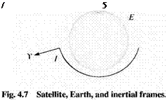
Problem. A satellite S is placed into a geosynchronous orbit. The onboard INS provides its initial orientation So wrt the inertial frame I by the rotation tensor Rs,)l (see Figure 4.7). To point the satellite’s antenna at the Earth ft, it needs to be adjust­ed such that its new orientation with respect to the Earth conforms to the rotation tensor RS, E. The most fuel-efficient way to torque the satellite is by direct rotation about an inertial axis. Provide the equations for the INS based attitude controller.

Solution. The rotation tensor to be achieved by the attitude controller is Rs l — RSl /;ftc/, where RE! is known from almanac tables. Therefore, the satellite has to be rotated by

RSlS,> = ftS|/ftSo/ = Rs’ERE! RSo1 (4.19)

Because the INS provides the main reference of the satellites, the unit vector of rotation should be declared in inertial coordinates. In preparation we express Eq. (4.19) in inertial coordinates

[RSAo]1 =

Yet. most likely, the RS’E tensor is given in Earth coordinates [ /?’’’ E]l:. Therefore, Eq. (4.19) becomes, in coordinated form,

Подпись:

Axis and Angle of Rotation

L Rs, s°]’ = [TYZiR^fm^lRZ’YiR^]1

With [f? SlSo]7 thus given, and its coordinates labeled as

f 11

П 2

r 3

Г2Х

Г22

Г23

-Гз

Г32

ГЗЗ-

Axis and Angle of Rotation Подпись: (4.21)

we apply Eq. (4.18)

and thus Eqs. (4.20) and (4.21) are the equations for the attitude controller.