Category Modeling and Simulation of Aerospace Vehicle Dynamics

General rotation

According to a theorem accredited to Euler,1 the general rotation of two frames can be expressed by an angle about a unit rotation vector. We set out to discover this form of the rotation tensor and ask, what are the elements of the rotation tensor in any allowable coordinate system ]й expressed in terms of the angle of rotation ф and the unit vector of the axis of rotation n Iй?

Our itinerary starts with the special rotation tensor [Z?]A of Eq. (4.10) and the special axis of rotation [h]A = [a3]A = [0 0 1], followed by the transformation

to any allowable coordinate system, say Iй, with the TM [ГIй4:

[tf]B = [T]ba[R]a[T]ba

[n]B = [T]BA[n]A

We reach our goal by expressing [і?]й such that it is a function of [nLt and ф only. Let us begin with rewriting [i?]A of Eq. (4.10):

0 0 0

[i?]A = cos ф[ЕА + (1 — cos ф) 0 0 0

0 0 1

‘Yo о

+ sin ф 1 0

0 0

Transforming to [Л]й,

0 0 0

[Я]в = cos ф[Е]в +(1 – cos ф)[Т]ВА 0 0 0 [t]BA

Подпись:

Подпись: 0 0 0 [Т]ВА 1 0 0 [Т]ВА 0 0 0 Подпись: 0 0 0 [Т]ВА 1 0 О [Т]ВА 0 0 0

0 0 1

Substituting Eq. (3.4) yields [R]B = cos ф[Е]в + (1 – cos f)[aiB[a^B + sin ir([a2]B[ai]B – [ai]B[a2]B)

(4.П)

Use the coordinates of the base vectors

a\

1

Q

1___

Гав1

“із

шв =

flB

. шв =

a22

, шв =

а23

„В

„Я

_a31_

_аЪ1_

_“зз_

to express the last term bracketed in Eq. (4.11): {[а2ВіаЛВ -Швтв)

О — авав2 + ав2а21 аиаз ~ а\а32

ав ав аПа22

– пв ПВ а2а2

0

а21а32 4” а22а3

-ав2ав{

+ “и

С1у2 а2аЪ2 а22а3

0

0

—“зз

ав 1 а23

азз

0

-“?з

~а23

«13

0

where we used the triad property [я31й = [A |]й[я2]й, with [Ai]B the skew – symmetric form of [ai]B. The last matrix has the skew-symmetric structure of [aUB which is also the unit vector of rotation ГА3]В = [ЛПВ. Replacing in Eq. (4.11) [a3]B, [A3]B by [пв, [ЛПВ yields

[R]B = cos – ф[Ев + (1 — cos ir)[n]B[n]B + sin i(r[N]B

Because ]B is any coordinate system, this equation holds for all allowable coordi­nate systems and, therefore, is the general tensor form of rotations

R = cos j/E + (1 — cos j/)nn + sin j/N (4.12)

So indeed, we confirmed Euler’s theorem that the rotation tensor is completely defined by its angle of rotation xfr and the unit vector of rotation n.

Example 4.2 Boresight Error

Problem. The seeker centerline s of a missile, carried on the right wing tip of an aircraft, is boresighted before takeoff to the aircraft’s radar centerline r (see Fig. 4.5). The antenna unit vector expressed in aircraft coordinates is [rB = [1 0 0]. In flight the wing tip twists upward by 3 deg about the wing box, which is swept back by 30 deg.

1) Calculate the elements of the rotation tensor [RMAB of the missile M wrt the aircraft A in flight.

2) Calculate the components of the seeker centerline in flight [л ]й and give the bore-sight errors in the aircraft pitch and yaw planes in degrees.
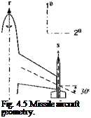
Подпись: Fig. 4.5 Missile aircraft geometry.

Solution. In general, the relationship between the missile and antenna center- line is

s = RMAr (4.13)

1) To calculate [RMA]B, we make use of Eq. (4.12) in body coordinates [Rma]b = cos ir[E]B + (1 – cos ir)[n]B[n]B + sin ir[N]B

With j/ = 3 deg,

Подпись: [RMA]B = 0.99863[E] +0.00137 Подпись: 0.25 -0.433 -0.433 0.750 0 0 Подпись: 0 0 0

[n]B = [-sin 30 deg cos 30 deg 0] = [-0.5 0.866 0]

0

0

0.866"

+ 0.05234

0

0

0.5

-0.866

-0.5

0

0.99897

0.000593

0.045326

-0.000593

0.99966

0.02617

-0.045326 –

-0.02617

0.99863

2) To calculate the missile centerline [.? ]11 in flight from the antenna boresight [r]s, we apply Eq. (4.13):

= [RMA]B{r]B =>• [5]B = [0.99897 -0.000593 -0.045326]

The second component is the displacement of the tip of the boresight vector in the 2B direction, which corresponds to an in-turning about the 3s axis (yaw) of —0.000593 rad or—0.034 deg. The third component moves the tip up and is therefore a positive pitch twist of 0.045326 rad or 2.6 deg.

Now we turn to a special rotation tensor with the angle i/r — 90 deg that describes the tetragonal symmetry of missiles.

4.1.2.4 Tetragonal tensor. Missiles with four fins possess tetragonal sym­metry, i. e., their external configuration duplicates after every 90-deg rotation about their symmetry axis. The rotation tensor that models these replications is called the tetragonal tensor Rgo – We derive it directly from Eq. (4.12) by setting xfr = 90 deg:

Rgo = ий + Л^

The tetragonal tensor is composed of the projection tensor P = nh [(see Eq. (2.21)] and the skew-symmetric tensor of the unit rotation vector N. An example should clarify the operation.

Example 4.3 Missile with Fins 90 Deg Apart

Problem. In Fig. 4.6, /| points to the root of fin #1. Use the tetragonal tensor to point to the root of the second fin f2.

Solution. With the base vector b as the unit vector of rotation, we have

f2 = R90fl=bbfr+Bfl (4.14)

The vector/2 is composed of the vector/, projected on b and the component that is the result of the vector product Bfx. With Fig. 4.6 you should be able to visualize this vector addition.

A numerical example can be of further assistance. Introduce the body coordinate system Iй. The vectors^ andf{ have the following coordinates in the body system: [b]B = [1 0 0] and [/, ]c = [/a /12 /13]. The tetragonal tensor becomes

‘1

0

o’

0

0

o’

‘1

0

o’

0

0

0

+

0

0

-1

=

0

0

-1

0

0

0

0

1

0

0

1

0

General rotation

Fig. 4.6 Tetragonal symmetry.

Applying Eq. (4.14), the second fin has the following coordinates in body axis:

"l

0

o"

fn

fn

0

0

-1

f2

-fn

0

1

0

_/l3_

fn

This result is confirmed by Fig. 4.6. The 1 coordinate remains unchanged; the second and third coordinates are exchanged with a sign reversal.

Special Rotations

Let us build up our confidence by constructing the general rotation tensor from special rotations. Beginning with planar rotations, we extend them to the third dimension and eventually obtain a general formulation that presents the rotation tensor in terms of its rotation axis and angle.

4.1.2.1 Planar rotations. In Fig. 4.31 have plotted two unit vectors b’, and c’, embedded in the plane subtended by the Iа, 2a axes of the coordinate system ]A. Unit vector c’ is obtained by rotating unit vector b’ through the angle ф. We determine the elements of the rotation tensor in the ]A coordinate system. From Eq. (4.1) we deduct, considering the two vectors as base vectors,

[c’]A = [R]A[b’]A (4.8)

To determine [??]A, we calculate first the components of the two vectors from elementary trigonometric relationships:

~СГ

A

"cos(e + ф)

”cos e cos ф — sin e sin ф

C2

=

sin(e – I – ф)

=

sin є cos ф + cos є sin ф

_C3.

0

0

3A


Special Rotations

Fig. 4.3 Planar rotation.


and


pi]

A

~cos e~

b’2

=

sine

kJ

0

Substituting both relationships into Eq. (4.8) yields

COS Є COS ф — sin є sin iff

r 11 Г2 rn

cos є

sin Є COS + COS Є sin l/r

Г21 Г22 Г22

sine

0

гзі r32 m

0

Подпись: [R]A Special Rotations Подпись: — sin^f ? cos xfr ? 0 ? Подпись: (4.9)

Our task is to establish the elements of the rotation matrix ry. By inspection we deduce the first two columns:

To determine the third column, we have to introduce the third dimension.

4.1.2.2

Подпись: 3A

Nonplanar rotation. We expand Fig. 4.3 to the third dimension and reinterpret b’ and c’ as the projections of the two vectors b and c of equal height (see Fig. 4.4). To determine the elements of the rotation tensor in the ]’4 coordinate

Подпись:Подпись: (4.10)Special Rotationssystem, we first recognize that the Iа, 2a coordinate axes of the two vectors [c]A and yb] A are the same as those of the planar rotation example just shown. Second, to determine the remaining last column we apply the fact that the third component of [c]A and [bA remains unchanged. Thus we supplement Eq. (4.9) and receive the three-dimensional rotation tensor

cos ф —sin ф 0 sin ф cos ф 0

0 0 1

Clearly evident is the similarity with the coordinate transformation matrix, but note that the negative sign of the sine function is two rows above the 1 entry and not right above it, as it is the case with coordinate transformations. Be careful however, this derivation is only valid if the rotation is about the third direction. The generalization occurs in the next section.

Properties of the Rotation Tensor

The orientation of a frame A is modeled by its base triad consisting of the three orthonormal base vectors «і, аг, and a (Sec. 3.1.1). Figure 4.1 shows the two frames A and В and their base triads. The orientation of frame В wrt frame A is established by the rotation tensor RBA, which maps the a, into the b, base vectors:

bi=RBAai, / = 1,2,3 (4.1)

Our first concern is whether RBA is a tensor. If we can show that it transforms like a tensor [see Eq. (2.4)], then it is a tensor.

Property 1

The rotation tensor RBA of frame В wrt frame A is a tensor, i. e., for any two allowable coordinate systems ]A and ]B with their transformation matrix T]LtA it transforms like a second-order tensor

Proof: Coordinate Eq. (4.1) by any two allowable coordinate systems, say ]4 and ]B,

[bt]A = [ЯМ]АЫЛ (4.2)

and

biL< = [ RBA ]z< I a,]R (4.3)

Because the base vectors themselves are tensors, they transform like first-order tensors, Eq. (2.3):

[ЬЛВ = [T]BA[bi]A (4.4)

and

[ai]B = [T]BA[ai]A (4.5)

Substitute Eq. (4.2) into Eq. (4.4) and replace [a, J‘4 by the transposed of Eq. (4.5) [bt]B = [T]BA[RBA]A[T]BA[ai]B Comparing with Eq. (4.3), we deduct

_ j-yjBAjAі’у’jBA

Because ]A and ]z< can be any allowable coordinate systems, RBA transforms like a second-order tensor and therefore is a tensor.

Property 2

Sequential rotations are obtained by multiplying the individual rotation tensors. For three frames A, B, and C and the rotation tensors RBA and RCB, the rotation tensor Rca of frame C wrt frame A is obtained from

2^ca_ rcbrba

Note the contraction of the superscripts: the adjacent B’s are deleted to form CA.

Proof: Let each frame A, В, and C be modeled by the triads a,-, bt, and c,, і = 1, 2, 3 and related by

bi = RBAat, a = Rc%, a = RCAdi, і = 1,2,3

Substituting the first into the second equality and comparing with the third one proves the property

d = RCBbi = RCBRBAaj => Rca = RCBRBA

Property 3

Rotation tensors, coordinated in preferred coordinate systems, are related to their transformation matrices. For any two triads at, bi, with the rotation tensor Rba, and the preferred coordinate systems ]A, Iй with the transformation matrix [T]BA, the following relationships hold:

[ЯЙА]А = = [T]BA (4.6)

Note first the surprising result that the rotation tensor has the same coordinates in both of its preferred coordinate systems. Furthermore, the rotation sequence is the reverse of the transformation sequel. This reversal becomes clear when we exchange the transpose sign of the TM for the reversal of the transformation order [RM]A = = уГ]АВ.

Proof: If the base vectors are coordinated in their respective preferred coordinate systems, they have the same coordinates:

[bi]B = [a,]A, / = 1,2,3 (4.7)

First substitute this equation into Eq. (4.2) and then replace [b, ]B by Eq. (4.4):

[bi]A = [RBA]A[ai]A = [RBA]A[bi]B = [Лм]л[Г]м[Ь,]Л

Because bi]A is arbitrary and certainly not zero, it follows that [Л“й4 ATUA = E and therefore [RBA]A = [T]BA. This completes the first part of the proof. Similarly, if we start with Eq. (4.3) and replace [&, ]B by Eq. (4.7) and then transpose Eq. (4.5) for substitution, we can prove the second relationship

[Rba ]B[ai)B = [bt]B = ША = [Т]ВА[щ]в =► [Rba]b = mBA

Combining both results delivers the proof

[^BA]A = = [f

Property 4

The rotation tensor is orthogonal.

Proof: It follows from Eq. (4.6) and the proof of Sec. 3.2, Property 1. Because the coordinate transformation is orthogonal, at least one matrix realization of the rotation tensor is orthogonal. But if one coordinate form is orthogonal, so are all and, therefore, the tensor is orthogonal.

Just as the determinant of the transformation matrix is ±1, so is that of the rota­tion tensor. Every such orthogonal linear transformation in Euclidean three-space preserves absolute values of vectors and angles between vectors. In addition, if the determinant is +1, it also preserves the relative orientation of vectors embedded in the frame. These are very useful properties, and therefore we limit ourselves to these rotations. The case with a “negative one” determinant is the reflection tensor, which we already encountered in Sec. 2.3.6.

Property 5

Transposing the rotation tensor reverses the direction of rotation RBA = RAB.

Proof: Exchanging the b and a, for both lower – and upper-case letters in Eq. (4.1) provides

dj — RABbj, і = 1,2,3 Substituting Eq. (4.1) yields

ai=RABRBAai, г = 1,2,3

Because a, is nonzero and the rotation tensor is orthogonal, RABRBA = £=> RllA = RAB.

We have established the rotation tensor as an absolute model of the mutual orientation of two frames. The nomenclature RBA expresses that relationship of frame В relative to frame A. You can read it as the orientation of frame В obtained from frame A, or just as the rotation of В wrt A.

No reference point is needed. Rotations are independent of points; they only engage frames. This independence becomes clear by an example. Suppose you stand on the east side of a runway and watch an airplane A take off and climb out at 10 deg. The airplane’s 10-deg rotation wrt to the runway R is modeled by Rar. On the next day you position yourself at the west end and watch the same airplane take off and climb out. The same Rar will give its orientation, although you changed your reference point from E to W. To define the airplane’s orientation, no reference points are needed.

Подпись: в
Properties of the Rotation Tensor

Fig. 4.2 Earth displays: a) flat and b) round.

Example 4.1 Conversion from Flat to Round Earth

Problem. You build a three-dimensional visualization of a long-range air intercept missile. Vectors of polygons model the missile shape. The simulation calculates the missile attitude RBF wrt a flat Earth. You are required to display the missile orientation over a round Earth. How do you convert the vectors of the missile shape?

Solution. The missile frame (geometry) is related to the flat Earth by RBF (see Fig. 4.2a). As the missile flies toward the intercept, the Earth’s local level tilts wrt to the flat surface by Rrf (see Fig. 4.2b). The orientation of the missile wrt the local level is therefore

Rbr = RbfRrf

Any geometrical vector of the missile, say tt, is oriented wrt the flat Earth by RBFtt and wrt the local level by RBRti.

Rotation Tensor

Actually, we are not quite finished with geometry. In Sec. 2.11 emphasized the importance of referencing points and frames to other points and frames. With the displacement vector % we model the displacement of point В wrt point A. For frames we shall ascertain that the rotation tensor JtIM references the orientation of the frame В wrt the frame A.

As we study the properties of the rotation tensor, we establish the connec­tion with coordinate transformations. Special rotations will give us more insight into the structure of the rotation tensor, and particularly, the small rotation ten­sor proves useful in perturbations like the inertial navigation system (INS) error model. Finally, a special rotation tensor, the tetragonal tensor, models the tetra­gonal symmetry of missiles, a feature we exploit in Sec. 7.3.1 for aerodynamic derivatives.

Rotation Tensor

Fig. 4.1 Frames A and В and their triads.

Kinematics of Translation and Rotation

After spending two chapters in the three-dimensional world of geometry, we are ready to launch into the fourth dimension, time. We will study kinematics, the branch of mechanics that deals with the motion of bodies without reference to force or mass. Later, in Chapters 5 and 6 we will add mass and force, apply Newton’s and Euler’s laws, and study the dynamics of aerospace vehicles.

If you watch the space shuttle take off at the Cape and track its altitude gain in time, you study its launch kinematics. However, if you are in Mission Control, responsible for ascent and orbit insertion, you concern yourself with the effect of mass, drag, and thrust and therefore are accountable for the dynamics of the space shuttle. Dynamics builds on kinematics. Hence we begin with kinematics.

I first introduce the rotation tensor, which defines the mutual orientation of two frames. It is the physical equivalent of the abstract coordinate transformation. Then I go right to the essence of the coordinate-independent formulation of kinematics and introduce the rotational time derivative. It will enable us in Chapters 5 and 6 to formulate Newton’s and Euler’s laws in an invariant form, valid in any allow­able coordinate system. Afterward you are ready for the discussion of linear and angular motions of aircraft, missile, and spacecraft in greater detail. Finally, we wrap up the chapter with the fundamental problem in kinematics of flight, namely, how to calculate the attitude angles from the body’s angular velocity.

Throughout these minutiae we shall remain true to our principle “from in­variant modeling to matrix simulations.” All of the forthcoming kinematic con­cepts are valid in any allowable coordinate system and thus are true tensor con­cepts. So welcome aboard, bring your tool chest, and I will fill it up with more goodies.

Local-level coordinate system

We conclude our exposition of coordinate systems with a special case of geographic coordinates, suitable for many aircraft and missile simulations. If the vehicle flies in the atmosphere with speeds less than Mach 5 (below hypersonic velocity), the Earth can be presumed an inertial reference frame. Furthermore, if the particular location on the globe is irrelevant to the simulation, any local tangent plane can serve as a geographic coordinate system, independent of the longitude and latitude designations. This special geographic coordinate system is called the local-level coordinate system. It maintains its fixed, level orientation, usually that of the launch point, although the vehicle is traversing the ground. Envision the longitude and latitude grid unfurled into this local-level plane. The vehicle’s trajectory is calculated relative to this plane, and altitude and ground distance are accurately portrayed. If you wanted to plot the trajectory on the globe, you could drape the ground track and altitude over the Earth’s curvature and assign longitude and latitude coordinates.

The local-level coordinate system ]L embeds its L and 2L axes into the hor­izontal plane and points the 3L axis downward. The direction of L is arbitrary, but, by convention, it is said to point north and the 2L axis to point east. For this reason it is sometimes also called the north-east-down (NED) coordinate system.

For those simulations that abide by these assumptions, you can replace the geographic by the local level coordinate system. The TMs derived in this chapter still maintain their validity. The body wrt geographic TM [TBG becomes [T]BL with the same Euler angles ф, в, and ф

cos ф cos в sin ф cos в —sin в

cos ф sin 0 sin ф — sin ф cos ф sin ф sin в sin ф + cos ф COS ф cos в sin ф COS ф sin в cos ф + sin ф sin ф sin ф sin в cos ф — cos ф sin ф cost? cos ф

(3.28)

Подпись: [Г]VL Подпись: cos у cos X -sin/ sin у cos / Подпись: cos у sin X cos/ sin у sin / Подпись: —sin у 0 cos у Подпись: (3.29)

and the velocity wrt geographic TM |T]’/G is replaced by [TVL with the path angles x and у

Distinguish carefully that ]L is associated with frame E but is not ]G.

Have you kept up with the number of coordinate systems? Without the inter­mediate systems ]x, and Y I count a total of nine. That does not include the geodetic system, which will be introduced in Sec. 10.1.2, or the perifocal system,

Подпись: System Подпись: Directions Подпись: Angles

Подпись:

Подпись: Heliocentric H Inertial I Earth E Geographic G Body В Wind aircraft W Wind missile A Flight path V Подпись: 1H—Aries Iі—vernal equinox Iі—Greenwich Iе' -north Iй—nose 1 W-vAB A-vj lr-vf Подпись: 3я—normal of ecliptic 31—Earth’s spin axis 3E—Earth’s spin axis 3G—Earth’s center 3B—down 3W—symmetry plane 3A—load factor plane 2V—horizontal plane
Подпись: Obliquity of the ecliptic £ Hour angle 3 Longitude / Latitude X Yaw tyy Pitch в Roll ф Angle of attack a Sideslip angle f) Total angle of attack a' Aero roll angle ф'

Table 3.2 Summary of coordinate systems and their transformation angles

the subject of an exercise. As we discuss practical implementations, a few more will make their appearance in conjunction with seeker gimbals, variable nozzles, and INSs. For now, however, Table 3.2 summarizes the coordinate systems and transformation angles of this section.

3.2.2.8 Summary. Surely by now you are thoroughly familiar with frames and coordinate systems. I hope I have convinced you that they are different entities and not synonymous. Just remember that frames are physical, whereas coordinate systems are mathematical models.

We discussed the representation of a frame by base point and triad. The location of its base vector and the orientation of the triad determine the position of the frame. I defined the important heliocentric, inertial, Earth, and body frames. Then we moved over to the mathematical ward and dissected coordinate transformation matrices. We found them to consist of base vectors expressed in preferred coordi­nate systems or direction cosines of enclosed angles. I will spare you the drudgery of repeating the coordinate systems and their transformations, but point you again to Table 3.2 for a summary.

This wraps up the geometrical part of our exposition. With our tool chest filled we can model lines, planes, bodies, and reference frames, and place them into the Euclidean space with coordinate systems. However, so far time has eluded us. Now we must bring time into play and embark for the shores of kinematics, the study of motions in space and time.

Problems

3.1 Position of an aircraft relative to a tracking radar. The position of an aircraft A with c. m. A is to be defined wrt to a tracking radar R and its antenna, represented by point R. The radar is referenced to north. How do you model the aircraft’s and the radar’s location and orientation. Be specific in your definitions. Make a sketch.

3.2 Conversion of satellite velocity. The velocity of a satellite S wrt Earth E is measured in geographic coordinates [uf ]G. What are its coordinates in the heliocentric system ]я? Use the TMs that were introduced in Sec. 3.2.2.

3.3 Aerodynamic force component conversion. The aerodynamic force/is commonly coordinated in the stability system ]s by its components lift L, drag D, and side force Y, [/]s = [—D Y —L], In six-DoF simulations, however,/is frequently expressed in body coordinates [f]B = X Y Z], Derive the conversion transformation between the two component forms.

3.4 Transformation matrix between satellite and inertial coordinates. The

normal satellite coordinate system ]s (see Ref. 1, p. 46) is used to express drag forces on a satellite B. The Is axis is parallel to the satellites inertial velocity v’fi, the 2s axis normal to the orbital plane, and the 3s axis in the general direction of the satellite’s displacement vector from the center of the Earth sB/. Given [u^]7 and [ід/]7 in inertial coordinates, express the TM |T]S7 in terms of these two vectors.

Local-level coordinate system

3.5 Angle of missile from north. The TM of the body wrt geographic coor­dinates TBG is given by Eq. (3.14). How do you determine the angle between the centerline of the missile and the north direction?

3.6 Euler angles of gyro dynamics. The elements of the direction cosine matrix, Eq. (3.14), contain the trigonometric functions of the Euler angles. More precisely they should be called the Euler angles of flight mechanics. In the study of the dynamics of gyroscopes, a different set of Euler angles is frequently used. Although the same symbols ф, в, and ф are adopted, the TM of body coordinates wrt inertial coordinates uses the sequence 3 > 1 > 3 and not 3 > 2 > 1 as in the case of flight mechanics. Make an orange peel diagram and derive the TM of gyro dynamics [T]BI with the sequence ]B <^—Y <~—x Compare the two

transformations. Are there any similarities?

3.7 Sequence of transformation is all important. The standard Euler trans­formation of flight mechanics [TBG is sequenced n <^—]G and

also called the 3 > 2 > 1 transformation. Let us reverse the sequence to 1 > 2 > 3 or]G +—~]x -^—]Y <^~]B and name it [T]GB. Sketch the orange peel diagram and derive T]GB. Is [T]GB the transpose of [T]BG? Why not? What is the sequence of transformation for the transpose of [T]BG?

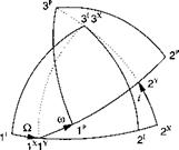
3.8 Perifocal coordinate system. The trajectory of a satellite is best described in the perifocal coordinate system. Determine the transformation matrix TPI of the perifocal wrt inertial coordinates given in the figure. The sequence of individual transformations is 3 > 1 > 3, or in symbolic form ]p ]x <—];, with

Q the longitude of the ascending node, і the inclination, and ш the argument of the periapsis. These three angles are part of the six orbital elements that describe size, shape, and orientation of a satellite orbit. The remaining three are the semimajor axis and eccentricity of the elliptical orbit and the time of the periapsis (closest point to the Earth) passage.

Local-level coordinate system

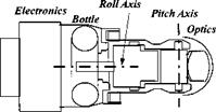
3.9 Seeker wrt vehicle transformation matrix. An infrared seeker head of a missile has two gimbals. Its inner gimbal with the optics and the focal plane array executes pitching motions while its outer gimbal allows for rolling excursions. Two coordinate systems are of interest: the body coordinates ]B with the 1H axis parallel to the roll axis, pointing forward, and the head coordinates ]H with the 2H axis parallel to the pitch axis, pointing to the right. Determine the transformation matrix [T]HB of the head coordinates wrt the body coordinates using the roll angle фнв and pitch angle Ohb – Sketch the orange peel diagram, clearly indicating the two angles.

Local-level coordinate system

3.10 Antenna angles and transformation. The main beam of a radar antenna is deflected by the azimuth az and elevation <?/ angles from the centerline of the missile 1B. The transformation sequence is 3 > 2 or symbolically ]A ]x Iй.

Make an orange peel diagram and derive the TM T]AB. What are the coordinates of the antenna base vector [a]B in body coordinates? What are the angles between Iа, 1B; 2a, 2b; and 3A, 3B? (Hint: Use direction cosine matrix form.)

1A

Local-level coordinate system

/

/

3B ‘

3.11 Initialization of flight-path angles. To initialize six-DoF simulations, it is most convenient to use the Euler angles і(г, в, ф and the incidence angles a, fi.

(a) Given these angles, derive the equations that determine the flight-path angles X and y.

(b) Introduce coordinate systems and express the equations in a form suitable for programming.

Wind coordinate systems

. Now the atmosphere thickens, and we take note of the air flowing over the vehicle. The air mass may be at rest or moving wrt the Earth. We assume, however, that it is monolithic, i. e., the air molecules re­main mutually fixed. This characteristic qualifies the air to be modeled as a frame A.

As the vehicle moves through the air mass, it experiences a relative wind over its body, which gives rise to aerodynamic forces. We introduce the wind coordinate system ]w. Only the Iw axis is defined unambiguously. It is parallel and in the direction of the velocity vector Vg of the c. m. of the vehicle В wrt the air A. The type of vehicle determines the other two axes. We distinguish between aircraft and missiles. An aircraft’s planar symmetry gives rise to the Cartesian incidence angles: angle of attack a and sideslip angle f, whereas missiles with rotational symmetry are frequently modeled by polar aeroballistic angles—total angle of attack a’ and aerodynamic roll angle ф’. We shall treat the TMs of wind wrt body coordinates for aircraft and missiles separately.

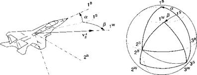
Cartesian incidence angles for aircraft. For aircraft the TM of wind wrt body coordinates [T]WB consists of two transformations with the interim stability co­ordinate system ]s. Unfortunately by convention, one cannot reach Jw from ]B by two positive transformations. The sequence is rather ]w ]v n with a negative alpha transformation (see Fig. 3.17). The stability system takes on a particular significance because both TMs [ T(a)ns and [T(f )ws are from its per­spective reached by positive angles. Therefore, we first derive these individual transformations and then combine them to form (TWB.

The stability coordinate system is defined as follows. The Is axis is parallel and in the direction of the projection of the velocity vector Vg on the symmetry plane Is, 3B, and the 2s axis stays with 2B. The TM [TWB is about this 2s axis by the angle of attack a

cos a 0 —sin a

[T]BS =010

sin a 0 cos a

The second TM [7’]’vs connects with the wind axis through the sideslip angle f>

Wind coordinate systems

3B

transformed about the 3 s axis

cos yS sin yS 0

[T]ws = — sin/J cos f) 0

0 0 1

Подпись:To arrive at our final destination, we multiply the two TMs but have to transpose first |T]B5, which has the effect of reversing the direction of the transformation,

Подпись: sin a cos P sin a sin p cos aПодпись: (3.18)cos a cos p sin p [7’]WB = —cos a sin p cos P —sin a 0

This TM distinguishes itself by keeping the 3W axis in the aircraft’s plane of symmetry and aligning it with the 3 s axis of the stability coordinate system.

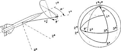
Polar aeroballistic incidence angles for missiles. For missiles with rotational symmetry, the load factor plane is more important than a body symmetry plane. It contains the total incidence angle a’ that gives rise to the aerodynamic force. As the stability axes subtend the aircraft symmetry plane, so does the aeroballistic coordinate system ]й line up with the load factor plane (see Fig. 3.18). In particular, the Iй and 3й axes lie in the load factor plane, with Iй coinciding with Iй. To change from the aeroballistic coordinates to the body coordinates, the aerodynamic roll angle ф’ determines the transformation ]в *^-]й about the Iй axis.

Wind coordinate systems

Because the wind coordinates for missiles are different than for aircraft, we rename them aeroballistic wind coordinates with the label ]A. Their Iа axis is defined just like the 1w axis for the aircraft, namely it is parallel and in the direction of the relative velocity vector vAB but its 3A axis lies in the load factor plane, and the 2a axis remains in the 2B,3B plane. The transformation of the aeroballistic

coordinates wrt the aeroballistic wind coordinates [Г]*4 is by the total angle of attack а’, ]й <^—A, about the 2A axis. From the orange peels of Fig. 3.18, we deduct the TM of the body wrt aeroballistic coordinates

1

0

0

0

cos ф’

sin Ф’

0

—sin ф’

COS Ф’

and the TM of the aeroballistic wrt the wind coordinates

cos a’

0

—sin a’

0

1

0

sin a’

0

cos a

Our goal is the TM of the aeroballistic wind wrt the body coordinates [ T ]AB. We get there in two steps. First, combine the two transformations (T]BA = [TriRTKA, and then take the transpose

j-j-jAB ___ j’j/JAj-j’jBB

Подпись: (3.19)cos a’ sin a’sin 0′ sin a’ cos ф’

Подпись: [T]AB =0 cos ф’ —sin ф’

—sin a’ cos a’ sin(// cos a’cos <p’

We have accomplished our task of deriving the TMs of the relative wind wrt the body coordinates for aircraft and missiles. If you compare Eqs. (3.18) and (3.19), you verify by inspection that they are not the same. Their transformation angles are dissimilar—Cartesian vs polar—and the wind axes are indeed defined differently.

From these TMs we can derive the definitions for the incidence angles in terms of the velocity components in body coordinates [йд]в — [и v w] and relative wind axes for aircraft дц w = [V 0 0] and missile [>g]A — [V 0 0], where V = vV + v2 + w2. The angle of attack a follows from the application of Eq. (3.18):

Kf =

V

cos a cos fi sin/З sin a cos fi

u

0

=

—cos a sin fi cos fi — sin a sin fi

V

0

—sin a 0 cos a

w

_

From the last line we derive

a = arctan (3.20)

To obtain a similar relationship for the sideslip angle fi, we use the two top lines V = и cos a cos fi + v sin fi + w sin a cos fi 0 = — и cos a sin fi + v cos fi — w sin a sin fi

Wind coordinate systems

Wind coordinate systems

1A P

■| w


Wind coordinate systems

(3.21)


A similar procedure provides the definitions of the polar incidence angles of mis­siles:


Wind coordinate systems

ф’ = arctan


(3.22)


(3.23)


Equations (3.21) and (3.22) are undefined for V = 0, a case of no interest to us, but v = w = 0 can happen in unperturbed flight, causing ф’ to be undefined according to Eq. (3.23).

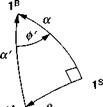
The relationship between the Cartesian and polar incidence angles can be derived from the spherical triangle that nestles around the Is axis. Superimposing the angles from Figs. 3.17 and 3.18 enables us to draw Fig. 3.19. It is aright spherical triangle that engages all four incidence angles. As an exercise, you should be able to derive


a’ — arccos(cos a cos fi)


ф’ = arctan


(3.24)


a = arctan(cos ф’ tan a’) fi = arcsin(sin0′ sin a’)


Wind coordinate systems

Wind coordinate systemsWind coordinate systems

Wind coordinate systems

Fig. 3.20 Flight path wrt geographic coordinates.


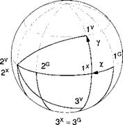
2V axis remains in the horizontal plane subtended by 1G and 2° (see Fig. 3.20). Two angles relate the velocity coordinates to the geographic system. The heading angle x is measured from north to the projection of vf into the local tangent plane and the flight-path angle у takes us vertically up to vf. The TM consists of the two individual transformations [T]VG = T (y )]VX[T (x)XG

cos у

0

—sin у

cos x

sin/

o"

0

і

0

-sin/

cos x

0

sin у

0

cos у

0

0

1

[TfG =

Подпись: [T]VG = Подпись: cos у cos X -sin/ sin у COS X Подпись: cos у sin x —sin у cos x 0 sin у sin X COS у Подпись: (3.25)

and multiplied

From this TM we can derive the definitions for x and у. Let the velocity com­ponents in the geographic coordinates be [nf ]G = [uG vg u>g] and in velocity coordinates [uf]v = [f 0 0]. The TM of Eq. (3.25) provides the relationship [vEB]v = [T]VG[vllG

V"

COS у COS X

COS у sin X

—sin у

0

=

-sinx

cos x

0

0

_

sin у COS X

sin у sin X

cos у

UG

Vg

WG

Подпись: X = arctan Подпись: VG UG Подпись: (3.26)

From the second line we glean

Wind coordinate systems Подпись: (3.27)

and you should also show that

Подпись:When you program these equations, you have to be careful with the arctan function because it is multivalued. Particularly, the heading angle can take on values from 0 to 360 deg. It is best to use the ATAN2 intrinsic routine that most computer languages provide.

Body coordinate system

The preferred body coordinate system is aligned with the body triad of Fig. 3.7. The Iя axis points through the nose of the vehicle and lies with the downward-pointing 3B axis in the plane of symmetry. The 2B axis, out the right wing, completes the coordinate system.

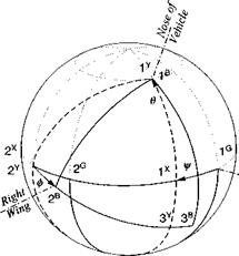
A prominent transformation matrix in flight mechanics is the TM of body coor­dinates wrt geographic coordinates TBG. It is composed of three transformations by the so-called Euler angles: yaw, pitch, and roll or ф, в, and ф. Two intermediate systems ]x and ]y are needed to complete the chain:

[T]BG = [Г(0)]ЯУ[Г(0)]га[Г(^)]хс

As Fig. 3.16 shows, the unit sphere is getting more cluttered, and you should be grateful for the orange peel rendering, showing only the essentials without coordinate axes jumbling up the picture.

Let us start the chain reaction with the geographic ]G to the first intermediate ]x system through the yaw angle i/r. The transformation occurs about the 3G axis.

Body coordinate system

3х = 3G

Therefore we have the pattern


cos ф sin ф 0 [T]XG = —si пф cos ф 0 0 0 1


The second transformation is about the 2X axis through the pitch angle # to the second intermediate system ]y:


Body coordinate system

1 0 0

[T]BY = 0 cos ф sin ф

0 —sin ф cos ф


Now it is just a matter of multiplying the three matrices to obtain the Euler trans­formation matrix:


cos ф cos 9

[Т]вс= cos ф sin 9 sin ф — sin ф cos ф cos ф sin 9 cos ф + sin ф sin ф


sin ф cos 9

sin ф sin 9 sin ф + cos ф cos ф sin ф sin 9 cos ф — cos ф sin ф


—sin# cos 9 sin ф cos 9 cos ф


Body coordinate system

# = arcsin(—0з)

and from the elements t\ and t2 the yaw angle


(3.15)


ф = arctan

and lastly from the elements ь3 and t33 the roll angle


(3.16)


ф = arctan


(3.17)


Body coordinate systemBody coordinate system

If you change the sequence of the matrices, you do not get the same transfor­mation matrix because matrix multiplications do not commute. However, because matrix multiplications are associative, you can change the order of the multipli­cations without changing the result. Convince yourself of these facts by using the matrices of this example.

Geographic coordinate system

As you become comfortable with the Earth system, you want to navigate on the surface of the Earth. A grid, blanketing the Earth’s surface, determines any point you want to reach. It consists of lines of longitude and latitude. Longitude is divided into ±180° with the posi­tive direction starting at the Greenwich meridian in an easterly direction. Latitude is measured from the equator, positive to the north from 0 to 90° and negative south.

Inside of simulations it is better to work with radians. Longitude can extend from 0 to 2л or ±л and latitude between ±л/2. Yet, to be kind to the customer, you can allow the data to be input in degrees, minutes, and seconds, and in turn you convert your output to the same units. The unit of arc minutes takes on a particular significance on a great circle like the longitude meridians or the equator because the nautical mile is defined as the arc length of 1 min. Ergo, the circumference of the Earth on the equator is 60 x 360 = 21,600 n miles.

At a specific point on the surface of the Earth, with its longitude l and latitude X, the geographic coordinate system ]G is defined as follows: The 1° axis points north, the 3° axis points at the center of the Earth, and the 2° axis, pointing east, completes the right-handed coordinate system.

To relate the geographic coordinate system to the Earth system requires a few steps (refer to Fig. 3.15). The first transformation is from ]E to an intermediate system ]x with the longitude angle Z, symbolically written as ]x <—]£, followed by another intermediate system ]F, obtained through the compliment of the latitude angle 90° — X, or symbolically ]r —— ]x.

3E з*

Geographic coordinate system

Fig. 3.15 Geographic wrt Earth coordinates.

Before we formulate the complete transformation, let us determine the TM of these two steps:

[T]YE = [7X90° – Я)]га[Г(/)]ж

sink

0

—cos Я

cos /

sin /

o"

II

0

1

0

—sin/

cos /

0

cos Я

0

sink

0

0

1

sin Я cos/ sin Я sin/ —cos Я —sin / cos / 0

cos Я cos / cos Я sin / sin Я

Notice the first transformation [T]XE is about the 3£ axis, followed by the trans­formation [T]1** about the 2X axis.

To reach the geographic axes, we have to make a 180-deg somersault. The 1G and 3G axes take the opposite direction of the lr and 3K axes, respectively, while the 2g axis maintains the same sense as 2V. How do we determine this TM? We go back to Eq. (3.5) and visualize the base vectors associated with the preferred coordinate system ]G being expressed in the ]y system. From this perspective we obtain the somersault transformation

Шг

‘-І

0

0"

Шг

=

0

1

0

[£зГ

0

0

-1

Stringing all of the transformations together,

[:T]GE = [7180o)]Gy [7X90° – Я)]га[7Х/)]ж

Подпись: -sink cos/ —sin / cos Я cos/ Подпись: —sink sin/ cos? —cosЯ sin/ Подпись: cos Я 0 —sink Подпись: (3.13)
Подпись: [T]GE

yields the important TM of geographic wrt Earth coordinates:

As a vehicle moves across the Earth, its longitude and latitude coordinates change and so does the TM [TGE. This phenomenon has led to the expression, “the geographic coordinate system is attached to the vehicle and its origin moves with it,” a perspective that attributes physical substance to coordinate systems.

We are taking the “road less traveled” and follow an interpretation that is con­sistent with our premise that coordinate systems are purely mathematical entities. If you inspect Eq. (3.13), all you see are longitude and latitude angles. The TM, therefore, does not depend on an origin moving with the vehicle. We need only the longitude and latitude angles of the vehicle. As it moves over the Earth, the directions of the coordinate axes will change. However, the altitude of the vehi­cle is irrelevant. Therefore, you do not have to keep track of a coordinate origin travelling with the vehicle. Coordinate systems have no origins!

The Iе and 2° axes are tangential to the Earth at the longitude and latitude of the vehicle. At least that is true for our current assumption that a spherical Earth is adequate for our modeling tasks. Later, in Sec. 10.1.2, for sophisticated six-DoF simulations we will consider the Earth to be a spheroid. There we will introduce the geodetic coordinate ]D, which is tangential to the spheroid at the vehicle’s latitude and longitude. Its 3D axis does not point at the center of the Earth anymore. This direction will be maintained by the 3G axis as before, and for that reason the geographic system will be renamed in that section as the geocentric system.

3.2.2.2 Earth coordinate system

The Earth coordinate system is the pre­ferred coordinate system of the Earth’s frame triad e, ei, and «з (see Fig. 3.6). Its Iе axis pierces through the unit sphere at the intersection of the equator with the Greenwich meridian. The 3E axis overlays the Earth’s spin axis, and the 2E axis completes the right-handed coordinate system (see Fig. 3.14).

To relate the Earth coordinates to the inertial coordinates, we have to heed the Earth’s rotation. Every 24 h the Earth presents the same face to the sun. This is called the solar day. However, a full rotation of the Earth relative to the stars, the so-called sidereal day, is actually shorter by about 4 min. The lengthening of the solar day is caused by the progression of the Earth on the ecliptic during 24 h. To present the same face to the sun, the Earth has to rotate further. We are interested in the sidereal time that has elapsed since the Iе axis coincided with the 11 axis. Rather than using time, however, we use an angular measurement, equating 360° to one sidereal day. The angle between Iе and Iе is called the hour angle E and establishes the Greenwich meridian relative to the meridian of the vernal equinox.

The transformation matrix [TJE/ of the Earth coordinates wrt the inertial coor­dinates is obtained by inspection:

cos S

sin S

0

—sin E

cos E

0

0

0

1

The rules, just given, should enable you to do the same. Figure 3.14 displays also the frugal orange peel schematic, which in its simplicity conveys all of the important information of the picture on the left.