Category Modeling and Simulation of Aerospace Vehicle Dynamics

Advanced guidance law

Proportional navigation, born in the waning days of World War II, is revalidated by modern control. We will employ optimal control techniques to derive the advanced guidance law in Cartesian co­ordinates. It can be shown that it encompasses the classical PN law, expressed in polar coordinates. The guidance command is a function of relative position and velocity and the time-to-go until intercept rg0. Of particular importance for the performance of this advanced guidance law (AGL) is the accurate calculation of fg0. It depends on the missile and the (unknown) target motions. I will derive the so-called circle time-to-go, based on circular engagements, which performs quite well in close-in engagements.

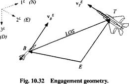
Before we can formulate the optimality problem, we investigate the engagement geometry. Figure 10.32 shows the missile В flying an intercept against target aircraft T. For this derivation we use the Earth E as the inertial reference frame, as it is common practice for air-to-air missiles, and the local-level coordinate system
]L. The displacement of the target wrt the missile is the difference between their displacements relative to the Earth reference point E

sTb = ste — sbe

Taking the rotational derivative wrt the inertial reference frame E

E>estb = DesTe — Desbe

produces the differential velocity v EB from the two relative velocities of Fig. 10.32

vEB=vE-vE

Refer back to Example 4.6 to renew your understanding of differential and relative velocities. A second derivative yields the differential accelerations aEB

Deveb = Deve — DEvB

E EE

aTB = aT ~ aB

composed of the relative accelerations. If we pick the ]L coordinate system, the rotational derivative becomes the ordinary time derivative, and we have

Подпись: HTB) d t = НІ~НІ (Ю.104)

Now we apply Newton’s law to the missile, with /sp the specific force and g the Earth’s gravitational attraction, and express it in ]L coordinates

Hf = i/spi" + [g]"

Substituting into Eq. (10.104) yields

Подпись: d t

Advanced guidance law

= H f – ([/sp]" + [g]") (10.105)

We neglect the target and gravity accelerations and interpret the specific forces as an instantaneous response to the acceleration command и = —[/sp]1". Furthermore,

Подпись: x = Fx +Gu Подпись: F = Подпись: ОзхЗ /зхЗ ОзхЗ ОзхЗ Advanced guidance law Подпись: (10.106)

we introduce some simplifications in nomenclature: As = [sjb]1; Av = vfBL x — [As Av]. Then the state-space formulation is

Note the very simple form of the dynamic equations. It is amazing how useful they are in applications.

We have made all preparations for the formulation of the optimal guidance prob­lem. For you to follow the derivation, you should be familiar with the foundations of optimal control or consult Stengel22 when you get lost.

Example 10.1 Optimality Problem

Problem. Find the control u(x. t) that minimizes the cost function

Подпись: uRu df1 1 Ґ

J = – x(tf)Sx(tf) + – J

Подпись:subject to the dynamic constraint x = Fx –

The performance index combines two important criteria for a successful inter’ cept. It minimizes the miss distance and limits the control power. The first term includes the weighting matrix S, which selects the square of terminal miss As(fy) from the state vector and weighs equally every component by ss.

Подпись: ^.9^3x3 ОзхЗ A s(tf) ОзхЗ ОзхЗ_ _Av(f/)_ ^x(tj)Sx(tj) — [As(tf) Av(f/)]

= ^■As(tf)As(tf)

The square of the controls are integrated over the engagement time, weighted by the 3 x 3 matrix R = r/3×3 and minimized. Apportioning values for ss and r emphasizes either the reduction in terminal miss or in control.

Solution. Introduce the Hamiltonian

H = jURu + A (Fx + Gu)

Advanced guidance law Подпись: A (tf) = Подпись: дф dx Подпись: (10.107)

The optimal solution for u(x, t) consists of the adjoint equation in the costate A

Подпись: A = —FA;X(tf) = Sx(tf)

and the optimality condition

Подпись: ЗмAdvanced guidance lawґдН

which provides the optimal guidance solution

u = – R’GX (10.108)

we just have to eliminate A.

Подпись: x' A Подпись: ' F -GRlG~ X _^6x6 -F A Подпись: (10.109)

For the elimination of X, you need to substitute Eq. (10.108) into Eq. (10.106) and combine it with Eq. (10.107) to get the state equations augmented by the costate

These linear differential equations can be solved using the state transition matrix Ф(г, to), which can be expressed in the fundamental matrix A of Eq. (10.109):

ф(г, r0) = eA(t~tB) = 112×12 + (t – to)A + (t~l°)2A2 + (t~f°)3A3 The state transition matrix is partitioned for x and A (assuming to = 0):

Подпись: 7зхЗ hxst 6г ^3х3 <2 і і 2г 73x3 Фп Ф12 ‘Фп Ф12 ОзхЗ hx3 2г ^3 хЗ — Lrhx3 Ф21 Фг2_ _XQ_ * _Ф2і ф22_ ОзхЗ ОзхЗ 7зхЗ ОзхЗ ОзхЗ ОзхЗ —hxit Нхз x(tj

X(t)

(10.110)

Notice that Ф21 is zero. The state transition matrix can also be used to solve the differential equations from any time t to final intercept time tf. This gives us the opportunity to introduce the time-to-go parameter fg0 = tf — t

Ф(?f, t) = Ф(tf-t) = Ф(Г80) Applied to Eq. (10.110), we obtain

Подпись:Фіі(^>о) Фі2(%о) x(t)

Обхб Ф22(%о)_ _A(t)_

From the first equation, after premultiplying by S, we get one expression

Sxf – 5Фц((6о)і + S<t>n(tzo)X

From the second equation we derive А/ = Фг2(^о)А, which is equal to Sxf ac­cording to Eq. (10.107):

Sx f — Ф22(^о)^“

Подпись: (10.111)Combining both, we can eliminate x/ and solve for A in terms of x A = [Ф22(??о) – £Фі2(Г§о)]-1£Фп(Г8о)л:

Now we can replace A in Eq. (10.108) and obtain the optimal solution solely as a function of the state де.

The optimal solution of guidance law consists of a gain multiplied by the state

u = K(tg0)x (10.112)

where

K(tgo) = – R~’GT[<S>22(tgo) – 5Фі2(%о)]_15Фп(%о) (10.113)

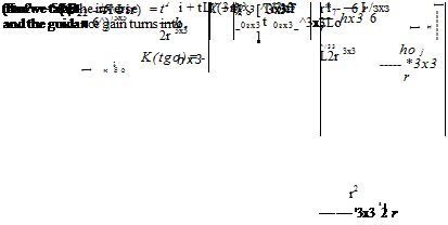
The guidance gain K(tg0) can be computed onboard the missile. It is a function of time-to-go, introduced through the state transition matrices. The other matrices are constant. To implement the guidance law, the differential position and velocity x — [As Av 1; As = sTb]l’, Av = [VjgL must be available to the missile guidance processor. This is by no means easily accomplished. IR seekers provide only LOS rates, which are insufficient for reconstructing the full state. RF seekers, on the other hand, measure range and range rate. They possess sufficient intelligence for the full state, but require a rather sophisticated Kalman filter. Possibly, the ultimate solution is the so-called third-party targeting. A surveillance platform downlinks accurate target position and velocity information to the missile. Onboard the missile the differential position and velocity are then formed in support of the guidance law.
Advanced guidance law
The gain includes a matrix inversion, which can be executed algebraically. First we substitute the values from Eq. (10.110)

Подпись: ihx3

Подпись: 3fg0
Подпись: ^ЗлЗ^о]-*-
Подпись: 3r +

Substituting into Eq. (10.112) and replacing the state by the differential position and velocity results in the control equation

(10.114)

Advanced guidance lawIf the control vector is not weighted, i. e., if unlimited control power is available, then r = 0, and Eq. (10.114) simplifies to the form of the actual AGL

Advanced guidance law(10.115)

with N = 3.

AGL is the PN law in Cartesian coordinates. It identifies the optimal PN gain as three. However, several air-to-air missiles operate with a higher gain—around four—to tighten up the guidance loop and to reduce the miss distance. Sometimes, the gain may even be scheduled as a function of the closing speed. In all cases, the selection must be based on extensive engagement studies that require full six-DoF fidelity and realistic noise models.

The implementation of AGL in a simulation takes the differential position and velocity from computed target and INS data [ігв]1"* [VjB]l and sends the acceler­ation command in body axes to the autopilot.

Advanced guidance law

Подпись: and in velocity and displacement components

(10.116)

What remains to be discussed is the calculation of time-to-go.

The quality of the guidance depends on the accuracy of the time-to-go estimate. If the future trajectory were precisely known, fg0 could be calculated error free. However, because the target is uncooperative, the missile trajectory cannot be predicted with certainty. Therefore, certain assumptions are made about both the missile and the target. The most obvious one being the straight-line extrapolation from the current conditions. Yet close-in combat is fought in circles, and these are the stressing conditions that the guidance law must excel under. We shall therefore base our fg0 estimate on circular engagements.

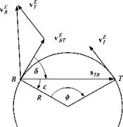
Figure 10.33 shows the geometry of a particular circular engagement. We assume that the differential velocity vfr of the missile В wrt the target T is tangential to a circle that contains both points with their displacement vector s tb ■ If the differential missile velocity remains on the circle and is constant, we can calculate the time until intercept from it and the length of the arc <pR:

(pR

Advanced guidance law

You can calculate the arc length by first determining the angle 8 from the scalar product of the two vectors [vBTL and [ігв]1-:

then expressing

є = 90 deg — 8

Advanced guidance law

Fig. 10.33 Circle engagement.

and

ф = 180 deg — 2s — 28

with

D krai

" — T———

2 cose

yields the arc length. The onboard guidance processor continually updates the time to go based on the v ‘Hr and Sjb intelligence. If the missile does not follow a circle, but executes a head-on straight-line engagement, ф = 0 and R — оо, and the calculation breaks down. This happens rarely in air-to-air engagements. If it occurs, it lasts only for a few integration steps, and you can program around it. I have had very good results for close engagements, and no problems with long fly-out trajectories.

10.2.5.3 Summary. As a faithful follower of my exposition, you should have a good grasp of the most important guidance laws for missiles: proportional navigation, compensated proportional navigation, and the advanced guidance law. Yet be forewarned; many variants of these basic schemes will pop up in missile simulations. I hope that you will recognize them as such and become emboldened to build your own.

10.2.4 IR Seeker

In Sec. 9.2.5 you read about the basic principles of IR sensors. You may have applied them to the gimbaled model that was introduced there. If you have working code, you can drop it straight into your six-DoF simulation and start flying.

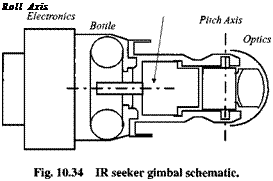
In this section we will develop another IR seeker, based on the current state of the art. Its mechanical arrangement consists of an outer roll and inner pitch gimbal. The focal plane array incorporates 128 x 128 elements with a resolution of 0.5 mrad and a total field of view of 3.6 deg. In clear atmosphere the detection range is 12 km. A particularly interesting feature is the so-called virtual gimbals,
Подпись: Roll Axis

which mechanize standard yaw and pitch gimbals in software. We deal therefore with two transformations, the physical gimbals of roll and pitch and the computer gimbals of yaw and pitch.

Unfortunately, the modeling task gets more complicated. Seeker kinematics is described by several transformations, and the focal plane geometry requires careful considerations. Adding uncertainties and errors poses further challenges.

Compensated proportional navigation

Let us briefly review proportional navigation. We choose the guidance law option, which calculates the acceleration command normal to the LOS to the target. Therefore, in Eq. (9.57) the unit vector uv specifically becomes the unit LOS vector mlos

apN = NV£1oiUlos — g (10.100)

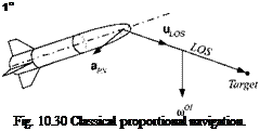
where N is the navigation gain, V the closing speed, $70/ the inertial angular velocity of the LOS wrt the inertial frame, and g the gravity bias. Figure 10.30 shows the vectors that construct this classical guidance law (disregarding g). The guidance command <*pn is normal to the LOS and lies in the so-called LOS plane.

You can visualize the engagement by fixing the target and flying the missile along its Is axis. The LOS rotates with the angular velocity of ш01 in the direction shown, and the vector product with mlos produces the direction of the command ары – Now, if the missile is thrusting and therefore accelerating along its Is axis with am, a parasitic acceleration component appears in the LOS plane that should not contribute to the homing guidance. In effect it introduces intercept errors and should therefore be compensated. If that error is corrected, the PN law receives the prefix “compensated.” We proceed deriving this compensation.

Refer to Fig. 10.31 for the geometric details. The missile’s longitudinal accel­eration am is projected into the LOS plane with the projection tensor PLos

ttmo — Plos rim

and subtracted from the PN command apN to obtain the augmented command

«G = «PN — Ото = «PN “ PLOS = NV n0IU LOS — P LOS^m

If we reintroduce the gravity bias, we have the form of the compensated PN law

aG = NVnOIuLOs – PiosOm ~ g (10.101)

It consists of the basic PN term and the compensation for missile acceleration (or deceleration) and the gravity bias. Notice that I derived it in the invariant tensor form, maintaining its validity in any coordinate system.

To coordinate the law for computer implementation, we proceed in two steps. First, express the guidance command ac in LOS coordinates, then, convert the two components from the LOS plane to body coordinates.

Let us begin with the transformation matrix [T]0B of the LOS coordinates relative to the body coordinates through the azimuth and elevation angles xJ/0B, 9qb, respectively.

Подпись:Подпись: (10.102)‘cos вов cos ir0B cos 90B sin ф0в – sin 90b ‘ – sin іД OB cosmos 0

,sin0oscos іДов sin Bob sin фов cos 90B.

With the missile acceleration vector given in body coordinates [am]B — [am 0 0], the guidance command is expressed in LOS axes (dropping again g for the time being)

[ac]° = [aPN]° – [PLOs]0[T]OB[am]B = [aPN]° –

"0 0 0" 0 1 0

[T]0B

dm

0

0 0 1

0

Gm

0

Подпись: = [apN]°

Compensated proportional navigation

-sin if OB sin 9ob COS xj/QB.

Now, we focus on the two components normal to the LOS, which are the com­mands for the autopilot. But because its accelerometers are body mounted, the commands must be converted to body coordinates. Using the (1,1) minor matrix

of Eq. (10.102), we relate the commands

Подпись: (flc)f (flc)f Подпись: cos фов sin вов sin f0B0

cos e0B

and solve for the body coordinates and combine them with the PN and missile accelerations

(ac)f

(apN)f sec – фов + tan іДов

-(apN)f tan вов tan ф0в + Оры)з° sec вов – ат tan в0в sec іДов_

The component along the missile Is axis was discarded because it contributes nothing to the target intercept.

To sum up, you first calculate the two components of the PN command (apN)^ and (ары)з’ based on the inertial LOS rate received from the seeker. Then, you combine them with the missile acceleration and bring back the gravity bias

Подпись:(flPK)f sec if OB + dm tan jf0B

-(flpN)f tan вов tan іДов + (арм)° sec Bob ~ am tan 0OB sec ров

(10.103)

You can find this implementation in the CADAC SRAAM6 simulation, Module С1. If you experiment with it, you will find that compensated PN provides some improved intercept performance during close engagements.

Compensated PN plays an essential role in many air-to-air missiles. It converts the inertial LOS rates into acceleration commands and steers the missile into the target. Some recent missile concepts, however, are equipped with strap-down seekers that deliver the target/missile dynamics in Cartesian rather than polar coordinates. For this application, the advanced guidance law, derived from optimal control, is in the right format.

Guidance

Guidance Guidance Guidance

With the INS model complete we have the first element of the guidance loop that wraps around the autopilot, actuator, and airframe dynamics (see Fig. 10.29). It fulfills the navigation function by delivering the position and velocity vectors of the vehicle. Given these states, it is the responsibility of the guidance processor to guide the vehicle according to the given flight objectives, by issuing commands to the autopilot.

Fig. 10.29 Guidance loop wraps around the inner autopilot loop.

Подпись: 1B Fig. 10.30 Classical proportional navigation.

The INS provides position and velocity relative to an inertial or Earth-fixed reference. If the target states are known—moving or stationary, the navigation solution can also be expressed relative to the target reference. Then, the onboard processor can also calculate inertial LOS rates in a format familiar from LOS seekers. We already encountered such seekers in Sec. 9.2.5, and in the next section you will meet an IR seeker. Their LOS rate output in the pitch and yaw channels is in the required format for the classical proportional navigation law.

In Sec. 9.2.4 we already discussed PN and line guidance. They are equally valid for six-DoF simulations because the outer guidance loop is little affected by the inner loop, as long as the autopilot is well behaved. In this section I extend the classical proportional navigation law by correcting for longitudinal missile accelerations and formulate the so-called compensated PN law. Another brief excursion into modern control will expose you to the derivation of the advanced guidance law for missiles with strap-down seekers.

Error equations for terrestrial navigator

10.2.4.4 . The terrestrial navi­gation system uses as its main reference the local geographic frame. Although it is an inertial instrument and subject to Newton’s equations, it emphasizes the local – level plane. In gimbaled systems the platform with its accelerometers is torqued to

Подпись: deR1,Подпись:INS Error Equation Tilt Equation Gravitational Error

Fig. 10.27 Implementation of the error equations of the space-stabilized INS.

remain level, as the vehicle proceeds over the curved Earth. Double integration of the specific force renders the ground distance. For strap-down systems the onboard computer maintains the direction cosine matrix. Although the accelerometers are mounted on the vehicle, the conversion to local-level coordinates is readily made through this transformation.

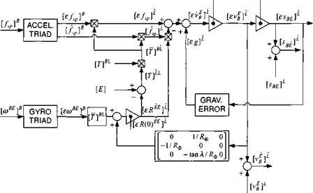
Because many of the six-DoF simulations are based on the flat-Earth assumption, the terrestrial navigator is particularly well suited for this approach. The inertial frame becomes the Earth frame and the inertial coordinate system the local-level axes. However, recall that the local-level plane is not just the local tangent, but the curved surface of the Earth unwrapped into a plane. To account for this effect, we introduce the coupling of the tilt to the velocity error via the Earth’s radius.

The INS error equation (10.92), already derived for the inertial-referenced INS, is now based on the Earth E as an inertial reference and the local level coordinate system ]L, as computed by the INS processor:

Подпись:Error equations for terrestrial navigator
L

= mBi[£/sp]B – [sRtE]L[T]BL[fp]B + [sg]L (10.95)

Подпись: d(£/?££) dr Подпись: = [f]BL[ewBE]B + Подпись: 0 1 /R@ -1 /Re о 0 —tank//?® Error equations for terrestrial navigator

The tilt equation (10.93) receives an additional term because the tilt error of a terrestrial navigator grows now also as a result of the velocity error

Error equations for terrestrial navigator Error equations for terrestrial navigator

Note in particular that the second component of the velocity error couples into the third tilt component through the term (tan a//?®), which is a function of the vehicle’s latitude a. We attribute gravitational errors only to altitude uncertainties (ssbi)b and neglect other effects. The change in magnitude of the gravitational acceleration is then based on Newton’s gravitational attraction

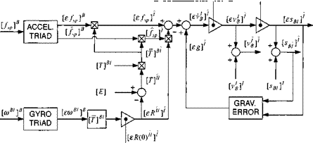
With these provisions we can modify the inertial-referenced INS of Fig. 10.27 and draw the schematic of the terrestrial navigator in Fig. 10.28. The Earth frame has become the inertial frame, and the computed inertial coordinates are replaced by the computed local-level coordinates. Notice the additional leveling loop that introduces the uncertainty in the calculation of the tilt rotation tensor [eT?££]L. The main output variables are the computed values of position [іВ£і£, velocity [rB]£, and the direction cosine matrix [T]BL. They are needed as input to seeker and guidance models, as well as parameters for plotting trajectory traces. You can find an implementation of the terrestrial INS in the CADAC SRAAM6 and SRAAM5 simulations, Module S4. It is suitable for both pseudo-five – and six-DoF simulations in conjunction with the Hat-Earth assumption.

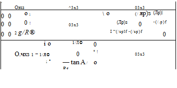
The error term in Fig. 10.28 can also be reduced to a linear state variable formulation if we drop the term of the specific force perturbations [£/sp]B in Eq. (10.95) and reverse the vector product of the tilt skew-symmetric tensor with the specific force. Introducing the error components

£S 1

■ K£]l =

£1>1

єф

£S2

£1>1

. [r££]£ =

єв

Є S3

£1>1

єф

Error equations for terrestrial navigator

[ev(0)ff [е*(0)в£]2

Error equations for terrestrial navigator

Fig. 10.28 Implementation of the error equations of the terrestrial stabilized INS.


popularized by Widnall and Grundy 8:

eij

£S 2 es3

£l)[

ev2

£V3

єф

ев

Подпись:Подпись:єф

(10.98)

These are nine first-order, linear differential equations, exhibiting the two major error couplings of local-level INS systems. The tilt vector couples with the specific force into the velocity derivative channel and the velocity vector couples with the Earth’s radius into the tilt derivative channel. The gravitational coupling occurs in the vertical channel between the altitude error and the vertical velocity derivative.

I found these equations particularly useful for Kalman-filter studies. To suppress errors, Kalman filters use navigation sensors to correct INS uncertainties. Embed­ded in the filter is a dynamic model of the INS error growth. In a typical simulation the actual error growth is modeled by Eqs. (10.95-10.97), while the Kalman fil­ter mimics this process with the simplified state model of Eq. (10.98). If you are interested in pursuing this topic, refer to the excellent references by Maybeck21
or Stengel.22 As an example, the CADAC CRUISE5 simulation, Modules SI, S3, and S4 illustrate the modeling and integration of a Kalman filter between sensor measurements and INS. Although written for a five-DoF application, the code is equally pertinent for six-DoF models. To follow the code, however, a sound foundation in filtering is a prerequisite.

As a final topic, 1 need to address the proper initialization of INS errors. In the real world the transfer alignment process initializes the INS. Any imperfections cause initial uncertainties of the nine states of position, velocity, and tilt. Similar uncertainties should initialize the error equations in the simulation. The transfer alignment errors are known stochastically by their covariance matrix Po, a 9 x 9 matrix of the variances and covariances of the nine-state vector єхо. For a particular simulation run we have to extract an initial error vector from the Gaussian distribution, represented by this covariance matrix.

The Cholesky decomposition will help us in this process by taking the square root of the covariance matrix у/Pq (you can use the subroutine MATCHO in the CADAC UTL3.FOR file). Combining it with a random Gaussian (9×1) vector, having unit standard deviation gauss, yields the initial INS error state

*0 = sfPo gauss (10.99)

A word of caution is appropriate at this point. The initial covariance matrix is not diagonal because the transfer alignment process intentionally couples states to reduce instrument and initialization errors. Therefore, a realistic simulation should not be initialized by stochastically independent states, but by correlated errors, as represented by a covariance matrix with off-diagonal covariances.

The modeling of INS is an important part of a high-fidelity six-DoF simulations. After staying with me through this much-abbreviated tour, you should understand the error equations that are found in the CADAC simulation examples. Perhaps you have even gained a general appreciation for the modeling of INS systems. However, to become better rooted in this subject, you should study in detail the recommended references.

. Gravitational error model

The dominant gravitational error is caused by the position error of the vehicle, i. e., the INS processor computes ve­hicle acceleration with an erroneous direction and magnitude of the gravitational vector. For the purposes of this derivation, we consider the gravitational field of a spherical Earth only. Any effects of higher harmonics are of lesser significance. From Newton’s equation of gravitational attraction (see Sec. 8.2.2),

T0000….o derive the gravitational error terms, introduce the perturbations of position and gravitational acceleration from Table 10.1:

/ f GM, f 7.

[g] – [eg]7 = – ………….. , – – ї(Ш’ – [eeB/]7

(кв/1 – Nb/I)3

If the first factor on the right-hand side is expanded into a binomial series

Подпись:. Gravitational error modelПодпись: 1-3GM – GM / |esB/lT3 / GM

(кв/|-|еев/|)з1%] кв/іЧ кв/І ГВІІ кв/І3

and terms of second order in є are neglected, we obtain

GM GM GM f

Подпись: JB/ і Подпись: 5 в/ Подпись: ’в/1

[g] – [eg] = ————– ^квЯ + і———- – т[еев/] + 3—— – гкв/] Іеев/І

where the underlined terms are satisfied identically because Newton’s gravitational equation also holds for the perturbed state. The gravitational error equation is then to first-order accuracy

[eg]’ = –—jlssBI]! – з-— квЛ’іеев/І (10.94)

кв/г кв/і

It exhibits the two important elements attributed to the INS navigation error. The first term on the right-hand side conveys the gravitational aberration caused by the location error [е^в/]7, and the second term reflects the error in the distance from the Earth’s center.

All of the elements are now assembled for completing the INS error model. Figure 10.27 depicts the mathematical flow of the equations already derived. First, focus on the three integrators. They represent the three triplets of state variables: velocity error, position error, and tilt. Their initialization is carried out during the transfer alignment of the INS.

The simulation provides the true specific forces and rates, measured and cor­rupted by the accelerometer and gyro triads. After conversion by the tilt transfor­mation, the specific force error is combined with the gravitational error to form the derivative of the velocity error. Like in the actual INS, two integrations lead to the position error. The major outputs of the INS model are the computed values of position [Sgj]1, velocity [t-’g]7, and the direction cosine matrix [T]BI.

You can find this INS error model in the CADAC GHAME6 simulation, Module S4. For a hypersonic vehicle an inertial stabilized INS is quite appropriate. More­over, the simulation builds on a legitimate inertial frame, which is a requirement for this type of model. For other simulations, based on the flat-Earth assumption, we have to proceed in a different fashion.

. Error equations for space-stabilized navigators

10.2.4.1 The space – stabilized INS is conceptually the simplest of all navigators because Newton’s

law assumes its most compact form when referred to the inertial frame. The error equations, based on the component perturbations of Chapter 7, form the basis for modeling the navigator of satellites or space ascent vehicles.

Newton’s law states that the inertial acceleration equals the specific force /sp acting on the vehicle plus the gravitational acceleration.

oVB=/sp+* (10.87)

For a space-stabilized navigator we choose the inertial coordinate system, but recognize that the specific forces are most likely measured in coordinates associ ated with the platform or the vehicle’s body.

= {tB,[fsP]B+ [g! (10.88)

The variables in this equation represent the true values, only known by God or the simulation. The values provided by the INS to the guidance processor are the so-called computed variables, which are corrupted by the INS errors. These errors, also called perturbations, are the difference between computed and true values.

Following the methodology of Chapter 7, the component perturbation of any vector x is

ex=x-Rux (10.89)

where x is the computed or corrupted vector and x the true variable. Perturbations of position, velocity, specific force, and gravitational acceleration can be patterned after this equation.

The rotation tensor R11 takes on particular significance. It is the so-called INS tilt tensor that relates the true inertial frame I to the computed frame I. Associated with the two frames are the true inertial coordinate system ]7 and the computed system J/, respectively. All information coming from the INS is expressed in computed coordinates.

Once we introduce these coordinate systems, the component perturbations are reclaimed:

[exl7 = [x]7 – [R7/]7[x]7 = [x]7 – [R11]’^]11 [x]7 and with [Я7/]7′[Г]" = [E]

[ex]7 = [x]7 – [x]7 (10.90)

This equation consists of column matrices, only valid in the chosen coordinate systems. It is not an invariant tensor formulation like Eq. (10.89).

Retracing the development in Sec. 4.1.4, the tilt tensor under small perturbations consists of a unit tensor and a skew-symmetric tensor

[R"]’ = [E]f + [eRn]r

where the perturbation tensor of rotation [see Eq. (4.26)] is expressed by the small

Подпись: Table 10.1 Perturbations of INS variables Variable Perturbation Velocity HI' - к I'-M' Position [«Bll' — [%■] ' - [SBI]' Specific force [eU]B = [/sp] Iй - l/sp]fi Gravitational acceleration teg]' = = [g]' - [g]' Coordinate transformation m" = [E]' - ■ [eR'1]'

angle components

‘ 0

—еф

єв~

eR"]1 =

еф

0

—єф

_ —eO

еф

0

which can be reduced to the tilt vector [r11]1 = [еф єв еф].

This tilt vector represents actually the attitude perturbation, as demonstrated by this simple exercise. Apply the component perturbations Eq. (10.89) to the tilt vector and recognize that the vector product is zero:

ev = r" – RIlr" =r

Indeed, the tilt vector is the tilt perturbation.

The tilt rotation tensor is related to the transformation matrix perturbation by

[ff = [R"]1 = [E]’ + [eR’1]’

and taking the transpose yields the perturbation of the coordinate transformation matrix

[T]" = [E]’ – [eRn]‘

In summary, for the derivation of the error equations I have provided the neces­sary perturbations in Table 10.1. Yet we still need to investigate the time derivative of the velocity vector perturbation. Apply the rotational time derivative wrt the perturbed inertial frame I to the velocity perturbation

Подпись: (10.91)D’ev’g = D’v’g – O’ (R"v’g)

The last term is expanded and D’v’B transformed to the / frame to obtain D’v

D'(R"vrB) = D’R"v’B +R” D’v’b = D’R"v’B + R" D’v’g +R"n"v’B

The first and the last term on the right-hand side can be neglected compared to the second term. Owing to the slow Schuler frequency (0.00124 rad/s), the time derivative D1 R" is negligible, and the term R"ft"v’B is small to the second order. With these simplifications Eq. (10.91) becomes

D’ev’g = D’v’g – R" D’v’g

and expressed in ]/ coordinates

The rotational derivatives have become the ordinary time derivatives. With [Rn]1 x [T]u = E] we have a relationship for the perturbed time derivative, which re­sembles Eq. (10.90):

the coupling between the specific force and the tilt, and the gravitational modeling error [eg]7. The specific force error [e/sp]B is a direct result of the accelerometer uncertainties, and the tilt [є/?77]7 is caused by gyro imperfections. From the INS navigation computation comes [T]BI, and [/sp]g is the output of the body-mounted accelerometers. We conclude from the error equation that the INS sensors play a dominant part in the INS quality.

10.2.4.2 Instrument errors. The gyros and accelerometers are either lo­cated on a gimbaled platform or mounted on the vehicle’s body. High-precision navigation systems have platforms—just look at the multimillion dollar INS of the Peacekeeper ICBM. Yet, advances in instrument technology and processing capa­bility have made it possible to replace the gimbals with mathematical models at much lower cost. These devices are called strap-down INS. As already mentioned, our error treatment applies to both; only the numerical values of the parameters reflect the different performance levels. In our discussion, however, we emphasize the strap-down implementation.

A strap-down INS, isolated from structural frequencies by vibration dampers, has two instrument clusters. Its accelerometer cluster consists of three instruments that sense the specific force along the three body axes, and the gyro cluster contains three rotary devices that measure the inertial angular velocity of the vehicle relative to the same three axes.

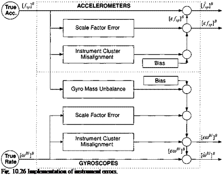
We model only those errors that remain after factory and prelaunch calibrations have taken place. These primary error sources for accelerometers are random bias and noise, scale factor error and misalignment. The same types of errors apply to gyros, augmented by mass unbalance for mechanical instruments.

The accelerometer error has the form

[e/sp]B = [eba]B + ([Se]B + [Ma]B)[/sp]B

consisting of the random bias and noise [sba]B, the diagonal scale factor error ma­trix [5„] , and the misalignment matrix [Ma]B. The misalignment matrix is skew symmetric, indicating the fact that a small misalignment exists between the ac­celerometer cluster and the vehicle axes. Within the cluster the accelerometer axes are assumed orthogonal. The output of the accelerometer cluster is the measured specific force in body coordinates

[/sp]B = [/s p]B + [£/sp]B

which is a combination of the true value [/sp]B, known only by the simulation and the instrument error [£/sp]B.

The gyro error is composed of similar terms

[sa>B,]B = [sbg]B + ([5,]B + [Mg]B)[a>B,]B + [Ug]B[f%p]B

consisting of the random bias and noise vector [sbg]B7 the diagonal scale factor error matrix [5A,]B, the skew-symmetric misalignment matrix [Mg]B, and addition­ally the diagonal imbalance matrix [UgB, which couples with the specific force. The misalignment again reflects only the cluster error of the otherwise orthogonal gyro triad. The output of the gyro cluster is the measured angular rate in body coordinates

[ftJB/]B = [ft, B/]B + [£WB/]B

composed of the true value [wB/]B and the instrument error [єшв!]в.

Подпись: Fig. 10.26 Implementation of instrument errors.

The tilt of the INS is caused by the gyro error and grows from some initial value, unless checked by external corrections. An integrator, initialized by the uncertainty of the transfer alignment, models this process:

Г її "l’

d SR“ – R, Dj r,

——- = [T]B,[swBI]B (10.93)

d t

Figure 10.26 summarizes the accelerometer and gyro measurement models. The true states, entering from the left and corrupted by the instrument errors, produce the measured values. Both pairs of output [/sp]B, k/sp]B and [cuB/]B, [ecuB/]B are essential for the INS error model.

Inertial Navigation System

Simulations of aerospace vehicles most likely require a model of an inertial navigation system (INS). I cannot imagine a modern missile or aircraft that does not employ an INS for navigation. There are the ballistic missiles with their high- precision gimbaled platforms, the passenger planes with laser gyros, and tactical missiles with inexpensive strap-down systems.

If you are tasked to simulate an INS, you can approach it from two aspects. Either you duplicate mathematically the functioning hardware with its imperfections, or you use the analytical error equations to corrupt the true navigation states. The first approach is used for detailed INS studies, whereas the analytical method is better suited for system-level performance studies. Our focus is on system simulations where I concentrate on the error equation approach and leave the more difficult task of hardware simulations to the experts.

Sir Isaac Newton unknowingly laid the foundation for inertial navigation. His second law states that position can be determined by integrating the vehicle’s acceleration twice. The acceleration is measured by an accelerometer. If the vehicle flew perfectly level, all we would have to add is a computer to carry out the integrations. However, missiles pursue targets, aircraft climb and descend, and satellites gyrate. To level the accelerometers, either they are mounted on a gimbaled platform, or a computer keeps track of the rotation between the accelerometers and inertial frames. For distinction, they are called either platform or strap-down INS.

The leveling of accelerometers requires gyroscopes. Their signals are used to ei­ther torque the platform or to determine the transformation matrix computationally. In both cases the so-called transfer alignment process will initialize them.

My treatment of INS simulations will be brief, with emphasis on error models that stood the test of performance studies. I assume that you have some familiarity with INS or are willing to acquire it by reading any of the standard reference texts. Two classics stand out, the book by Britting17 and a report by Widnall and Grundy.18 Britting treats a variety of INS systems from space stabilized to local-level platforms and strap-down systems. He painstakingly shows that the error equations of all of these various mechanizations can be condensed into one analytical form. More recent texts include detailed accounts by Chatfield19 and a broader treatment by Biezad.20

The fundamental equations of INS navigation, based on Newton’s law, calculate the velocity of the vehicle c. m. wrt the inertial frame in inertial coordinates [iJg]7 and its position wrt an inertial reference point /, [sg/]7 in inertial coordinates

Подпись: сЬ'д/ dt Inertial Navigation System

d t

with [ /sp]B the specific force measured by the accelerometers, and [g]7 the gravi­tational acceleration in inertial coordinates. The accelerometers could be mounted on the vehicle or on a platform. In either case ]B stands for the coordinate system

Inertial Navigation System

{v’b}’

Inertial Navigation System

[Rm[ 0)]B

Fig. 10.24 INS principle of operation.


associated with that frame. The integration of the gyro’s angular velocity of the vehicle wrt the inertial frame, expressed in inertial coordinates [шш]1, delivers the rotation tensor of the body frame В wrt the inertial frame | RBr! = T]BI. Figure 10.24 depicts these operational equations in block diagram form. Starting with the acceleration alB]B and rate [coBI B measurements, the transformed specific force, combined with the gravitational acceleration, is integrated twice to attain the vehicle’s position track. Six differential equations have to be solved for the basic navigation solution. Another four quaternion differential equations calculate the attitude angles.

Because the focus is not on the actual hardware, but rather on the error contri­bution of the INS to vehicle performance, I concentrate on their error equations. Both, the inertial and local-level systems will be discussed, for space and atmo­spheric vehicles, respectively. My approach is to corrupt the true values by the INS errors, thus providing the computed navigation data to the rest of the sim­ulation. Figure 10.25 shows the process of modeling navigation parameters with uncertainties. The є indicates perturbations, and the caret reflects computed values.

Are you ready to plunge into the details? As you will see, I shall make use of the perturbation methodology of Chapter 7 and derive the error equations of the space-stabilized navigator. To attain the error equations of terrestrial navigators, I elevate the Earth to an inertial frame and introduce the leveling feedback. A state-based formulation will round out the discussions.

Thrust vector control

Instead of using aerodynamics to turn the vehicle, thrust vector control employs propulsive moments to increase the inci­dence angle and thus maneuvers the vehicle through the ensuing aerodynamic forces. Outside the atmosphere, in the absence of aerodynamics, direct force con­trol must be applied, using reaction control jets. We limit our discussion here to the endo-atmospheric application of thrust vector control.

A common feature is the deflection of the propulsive vector from the vehicle centerline in order to produce a moment about the vehicle’s c. m. The deflection can be produced by turning the exhaust plume with jet tabs, like the original German V2, by pintel nozzles or titling the whole nozzle assembly. In either case the simulation model is the same. We use the moving nozzle as an example.

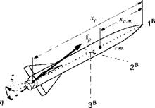
Figure 10.23 explains the geometry. The moment arm is the distance between the throat of the nozzle and the c. m. of the vehicle: Д* = xp — xc m. |. (As a reminder of what you learned in earlier chapters, I have drawn the body axes not

Thrust vector control

through the c. rn.). The nozzle deflection is given by yaw angle £ in the 1B, 2B plane and the pitch angle r) in the displaced 1B, 3B plane. With the sequence of transformation of the nozzle coordinates wit the body coordinates ]B,

you should be able to derive the following transformation matrix:

Подпись: sin t] 0 COS 11 COS £ COS tj sin £ COS 7] —sin£ cos£

COS £ sin Г] sin £ sin T]

The thrust force in body axes is

ifP]B = mNBuP]N

where [fp]N = |f 0 0] with t as the thrust magnitude. Substituting the transfor­mation matrix yields

Подпись: lfP]B =cos ri cos £
cos г) sin £ t
—sin Tj

The vector product of force and moment arm produces the moments about the c. m. that turn the missile:

0

-Up) f

Up) B2

Up) f

0

-Up)?

-Up)!

Up)?

0

0

— sin Г]

txp

-^c. m. 1

— COS Г] sin £

[mp}B =

Thrust vector control

Either a positive £ or tj causes a negative moment. Notice also that the force components oppose the maneuver, just as it is the case with aerodynamic controls. For instance, a positive t] produces a force component (fp)B = —t sin??, which counteracts the pitch-down maneuver. This adverse control force is noticeable at the beginning of the maneuver until the aerodynamic force, produced by the incidence angle, overpowers it. To avoid this effect, aerodynamic control surfaces and reaction jets have been placed forward of the c. m. Located there, they actually aid in the maneuver.

A drawback of TVC is the lack of roll control. Twin nozzles and peripheral reaction jets have been applied to overcome this deficiency. However, they come at a cost and performance penalty.

The dynamic response of gimbaled nozzles can be patterned after the model we used for aerodynamic controls Fig. 10.21. With two gimbals we introduce the r and £ actuators into the control loop. Typical values for their deflection and rate limiters are 10 deg and 100 deg/s, respectively. You can find applications of TVC in the CADAC SRAAM6 simulation, Module C3.

Aerodynamic controls

The most widely used method to control endo-atmospheric vehicles is through aerodynamic surfaces. By deflecting them, moments are generated about the c. m., which in turn rotate the airframe. The re­sulting incidence angles generate aerodynamic forces, which accelerate the vehicle in the desired direction.

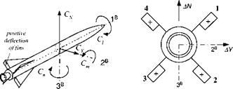
We start with the description of missiles, followed by aircraft. Figure 10.20 dis­plays the positive sense of the aerodynamic moments and the convention of positive

Aerodynamic controls

viewed from the rear

surface deflections. There are only three moments, rolling С/, pitching Cm, and yawing C„, but four surfaces to produce them. Therefore, the four surface deflec­tions 51, 52, 53, and 54 are combined to compute three apparent controls, called roll Sp, pitch Sq, and yaw Sr:

Sp = i(—51 – 52 + 53 + 54)

5^ = 1(51 + 52 + 53 + 54) (10.85)

Sr = ±(-51 + 52 – 53 + 54)

A fourth relationship does not result in a moment, but only in a pure axial force:
Sd = 1(51 – 52 – 53 + 54)

By the way, the proposal has been made to exploit this drag force for retarding a reentry missile.

Unfortunately, no consensus exists concerning the positive sense of control surfaces for missiles. We follow here the recommendation of the former North American Aviation Corporation. Another convention defines the surface deflec­tions as positive when they contribute to a positive rolling moment. Our approach (see the following equations) has the advantage that it agrees with aircraft conven­tions for positive control deflections.

Roll:

+Sp —»■ + AC; rolling moment

Pitch:

+Sq —»• +AC, v normal force

Yaw:

+5r —► +ДСу side force

Positive roll control (aileron) produces a positive rolling moment; positive pitch control (elevator) generates a positive normal force (but a negative pitching mo­ment); and positive yaw control (rudder) creates a positive side force (but a negative yawing moment).

The missile autopilot sends the roll, pitch, and yaw commands to the actuators. Yet, before they can be utilized, they have to be separated into individual fin commands:

51 = —Sp + Sq — Sr

52 Подпись:= —Sp + Sq + Sr

53 = +Sp + Sq — Sr

54 = +5/? + Sq + Sr

then each actuator module can convert the fin command Sic into an actual surface
deflection Si, where і = 1,2, 3. 4. We represent the response of the fin actuator

DDLIMX DLIMX

Aerodynamic controls

Fig. 10.21 Block diagram of fin actuator.


by a second-order transfer function

Si{s) _ col__________

8ic(s) s2 + 2i;cons + со2

with natural frequency con and damping t,. Although the transfer function models only the linearized dynamics, we include two important nonlinearities as portrayed in Fig. 10.21. DLMIX limits the deflection of the fin, and DDLMIX restricts the maximum fin rate. Limiting the fin rate should not be neglected because it can become the source of serious performance degradation.

This actuator facsimile is the standard model of the CADAC six-DoF sim­ulations. Its implementation calls for careful coding of the limiting feature of the derivative 8i. For details you can consult the CADAC SRAAM6 simulation, Module C4.

Подпись: 1B

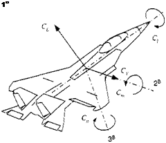
The same model is also used for aircraft-type vehicles, like cruise missiles, hypersonic vehicles, and, of course, the FALCON6. Some simplifications however apply. The basic control surfaces of aircraft are aileron 8a, elevator 8e, and rudder 8r. Autopilot commands can be fed directly to the surface actuators. Their positive directions are shown in Fig. 10.22. Aircraft control conventions, like those in the following equations, are similar to missile control.

Aileron:

+Sa —»• +ДС/ rolling moment

Elevator:

+Se —>■ +ACl lift force

Rudder:

+Sr -* +ACy side force

Again, only the aileron deflection produces a positive rolling moment. Elevator and rudder cause negative moments, while their positive sense is defined by the positive forces they produce.

For programming purposes we can copy the code of missiles, as represented by Fig. 10.21, and insert it into our aircraft simulation. I have done so for the CADAC GHAME6 simulation, Module C4.

Aerodynamic surfaces are sometimes inadequate to control the vehicle. Greater agility may be required of a missile. A hypersonic vehicle can reach such heights that, despite its velocity, the dynamic pressure has fallen below acceptable values. For these applications thrust vector control could be the solution.

Actuator

In gliders and small airplanes the pilot’s stick movements are sent directly by cable to the control surfaces. His muscle strength is sufficient to overcome the small control moments. In larger airplanes, however, mechanical or electrical devices must boost the human power. Moreover, if you take the man out of the loop, as for instance in missiles, and replace him by low-voltage autopilot signals, considerable amplification and power input are required to move the surfaces. The devices that deliver that boost are called actuators.

An actuator is a device that actualizes steering inputs to motivators. These moti­vators can be aileron, elevator, and rudder, or could be gimbaled nozzles of rockets. Even reaction jets are grouped into this category. We distinguish accordingly be­tween actuators for aerodynamic control, thrust vector control (TVC), and reaction jet control systems (RCS). Hydraulics, pneumatics, or electromehanical devices can accomplish the power amplification. Power consumption, size, and cost are important selection criteria.

For six-DoF simulations we are mostly concerned with the accurate modeling of the dynamic characteristics of these devices. Needless to say that actuator com­panies, like Chandler Evans, invest great resources in presenting to the customer accurate performance specifications. These include mathematical models that can be used in system simulations for performance studies. The models are of high order and include all known nonlinear effects.

My purpose is less ambitious. I want to show you simple models, which nonethe­less convey the salient characteristics of actuators. Most likely, you will have to model actuators for aerodynamic and thrust vector control. The more esoteric RCS are used for precision steering in exo-atmospheric vehicles, as direct force motivators. Their response is so fast that static modeling is sufficient.