Category Modeling and Simulation of Aerospace Vehicle Dynamics

Line guidance, vector case

If you are theoretically inclined and want to see some vector and tensor mechanics in action, you will like this general derivation of line guidance. We will start with the two conditions for line guidance, derive the vector form, convert it to tensors, and eventually express it in matrices for programming. Equations (9.59) and (9.61) will be fully recovered.

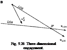
The principle of line guidance is stated as follows (see Fig. 9.26): If the vehicle В is positioned on the LOA and the velocity vector v § points at the target, then the two vector products of the unit vectors mLOs and Hloa are zero:

єР = F|hLos = 0 and eL = У|иШа = 0 (9.62)

Єр is the so-called point attack error, employed to correct LOS errors, and eL is the line attack error, used to bias the velocity vector towards the LOA. If both errors are zero, the vehicle flies on the LOA toward the target. We combine them with the variable gain G for the total error vector

є = Єр — G Єр (9.63)

Єї opposes Єр until the vehicle has reached the LOA. For this reason the Сєь term is also called the line bias term.

The commanded acceleration is the vector product of the total error є and the velocity vector Vuv multiplied by a constant gain К (note A is the skew-symmetric form of є):

a — KVEuv (9.64)

The acceleration vector acts normal to the velocity vector and is zero if the total error is zero, or if є is parallel to uv, which never occurs. Substituting Eq. (9.63) and then Eq. (9.62) into the last equation yields

a = KV{EPuv – GEluv) = KV(UVUL0Suv – GUVUloam„) (9.65)

The two terms on the right-hand side are vector triple products (see Sec. 2.2.5.1). They convert to

Подпись:Подпись: В Fig. 9.26 Three-dimensional engagement.
a = KVlupos — uvuvuLOS — G(hloa — м„й„иша)]

We abbreviate the two terms by introducing the point guidance vector c p and the line guidance vector cl

Cp = «LOS — «i.«i)Mlos; cL — «LOA — «d«d«LOA (9-67)

and, combining it with the gravity bias term g, we obtain the three-dimensional line guidance law

a = KV{cp — Gcl) – g (9.68)

The point guidance vector generates an acceleration command that drives the missile toward the intercept point, biased toward the LOA by the line guidance vector and its gain.

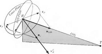
The two control vectors have a geometrical interpretation. Rewriting Eq. (9.67), we recognize the plane projection tensor Nv = E — uvuv of Sec. 2.3.5:

cP=(E – «^«„Imlos = A„«los» cl=(E – «„«,.,)«loa = A. mloa (9.69)

This plane, normal to the velocity vector, is called the l a tax plane after the British designation for lateral acceleration of a missile. It contains the two control vectors, which are just the projections of the unit LOS and LOA vectors, respectively. Because both control vectors lie in the latax plane, then so does the acceleration command.

We are now ready to derive the component Eqs. (9.59) and (9.61) from the vector Eq. (9.68). To carry out our objective, we have to employ some geometry. Figure 9.27 displays the engagement of missile В against target T. For clarity, it depicts only the formation of the point guidance vector c p (the projection of the unit LOS vector «los on the latax plane). The line guidance vector would be formed by a similar projection of the unit LOA vector.

To develop the component equations, we use an alternate route to form the point guidance vector. Instead of «los> we project the unit velocity vector uv on the LOS plane and rotate the projection through the rotation tensor Rvo of the velocity frame V wrt the LOS frame О. The resultant vector is in the opposite direction of

Line guidance, vector case

the point guidance vector. Expressed in mathematical terms, we summarize

cP = —RV0N0uv (9.70)

where No is the planar projection tensor onto the LOS plane. This relationship is valid in any coordinate system. In particular, c p should be expressed in velocity coordinates ]v and uv in LOS coordinates ]°

[cP]v = -[Rvo}v[T}vo[No}0[uv}0 = -[N0]°[uv]° (9.71)

where [RV0]V[T]V0 = [E] [see Eq. (4.6)].

We build the line guidance vector by a similar process

cL = —RVFNFuv (9.72)

where Np is the planar projection tensor onto the plane normal to the LOA. Its component form is in velocity coordinates ]v and LOA coordinates )F

[cL]v = -[7?v’F]v'[T]v’F[Af]f [uv]F = -[AF]F[«„]F (9.73)

Substituting Eqs. (9.71) and (9.73) into Eq. (9.68) and multiplying out the matrices yields the line guidance law in component form

Подпись: cos у sin у cos x sin у sin X
Подпись: cos у cos/ -sinx sin у cos/
Подпись: sin у "о" 0 0 cos у

[a]v = KV(~[N0]°[uv]° + G[NFf[uvf) – [ТУ1]#

(

"о 0 о"

‘о 0 о"

К£)Г

К

0 1 0

К£)2°

+ G

0 1 0

{4)1

V

0 0 1

К)з°

0 0 1

[4)1

/

0

К

– g

—sin у 0

К

– (»!)? + с«)[]

cosx

These are Eqs. (9.59) and (9.61) and the derivation is complete.

Line guidance, scalar case

In some applications it is desirable that the target point is approached from a certain direction. For instance, an aircraft coming in for a landing must, while descending along the glide slope, line up with the the runway and approach an initial point (IP) at the beginning of the runway before touchdown. The IP is the target point, and the heading and depression angles define the approach line. A second example describes the delivery of submuni­tions against tanks traveling on a highway. The cruise missile, which carries the submunitions, must approach in the direction of the highway and start dispensing the submunitions at the head of the tank column. Again, an approach line and IP must be defined. Other applications include the delivery of hard target warheads along a steep trajectory, reconnaissance flights along railroad tracks, and waypoint guidance with desired headings.

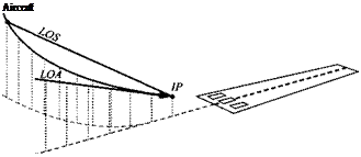
The task of line guidance is to align the vehicle toward the line and keep the velocity vector aligned until the vehicle flies through the IP. We call this line the line of attack (LOA) in contrast to the LOS, which is the line between the vehicle c. m. and the IP. Figure 9.24 depicts the geometry for the landing approach of an aircraft.

The objective of line guidance is to drive the LOS toward the LOA. As they merge, the aircraft will fly through the IP along the desired approach line. Let us first derive the governing law for horizontal steering, which can be visualized as the horizontal projection of Fig. 9.24.

Подпись: Aircraft

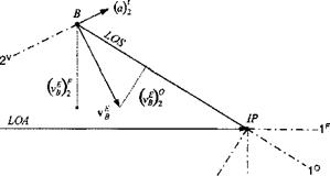
In addition to the LOS coordinate system ]°, we define the coordinate system F associated with the LOA of the final approach (see Fig. 9.25). The velocity of the aircraft В wrt the Earth frame E is vf, and its two components in the 2 direction of the ]7′ and ]° coordinates are (uf )£ and (v^)®■ To accomplish the objective of line guidance, both components must be driven to zero by the acceleration command, normal to the velocity vector. From these considerations we formulate

Line guidance, scalar case

/

Fig. 9.25 Line guidance engagement in horizontal plane.


the horizontal line guidance law

Подпись: (9.59){a)v2=K[-{vEB)°+G(vEB)F2}

The velocity vector is turned towards the IP if the acceleration command {a) reduces the (uf )0 component. The aircraft c. m. В is moved faster toward the LOA if (a)2 increases the (vB)[ component. The G gain balances the two terms, and the К gain adjusts for the different units. When vf is on the LOA, both components are zero. Gain К is the guidance gain and is usually selected to be constant with values between one and three. The bias gain G, on the other hand, needs to decrease as the aircraft approaches the IP point, or else, dynamic overshoot can prevent the aircraft from flying through the IP. I found an exponential decrease suitable for all applications

Line guidance, scalar case(9.60)

where |5гв| is the distance of the vehicle to the IP and d is the norm distance at which the gain has the value G = 0.633. A typical value is d = 1000 m.

The development of the line guidance law for the vertical plane is similar. Applying Eq. (9.59) to the third directions of the coordinate systems ]v, ]°, and ]F yields

Подпись: (9.61)(а)з = K[-(vEB)° +G(uf)[] g cos YL

with the gravity bias term g cos Yi. Note that (a)^ is positive down and normal to the velocity vector v f. For small angles of attack the normal load factor command is approximately aNc = — (a)^; otherwise, we use амс = — (a)^ cos a. In the horizontal plane the lateral acceleration command is aic = (a)^ ■

Most line guidance applications have a fixed IP point (or target) from which emanates a fixed LOA. As an extension, only slow target movements compared to the missile speed can be accommodated. If G = 0, we have the special case of
point guidance, also called pursuit guidance, with the velocity vector of the vehicle pointed at the target, irrespective of the approach direction.

CADAC implementation of PN

For five-DoF CADAC imple­mentations the guidance law is programmed in the Cl Guidance Module (see Fig. 9.23) and provided with the necessary input from the Seeker Module S1 (see Fig. 9.30) and the INS Module S4. The two components of the acceleration signal are converted to units in gs and sent as normal acceleration command а^с and lateral acceleration command du to the autopilot (see Autopilot Sec. 9.2.3.1). The third component parallel to the body 1 axis is not used.

The key design parameter is the navigation ratio N. It usually is a constant but could be made a function of the closing speed between target and missile. To determine its value, start with the number three and conduct sensitivity studies

CADAC implementation of PN

throughout the engagement envelopes. You will have to compromise and empha­size the more probable intercepts.

We have succeeded in modeling the PN guidance law, but only in its simplest form. The more complex form of thrust-corrected PN is reserved for Sec. 10.2.5.1. Let us now turn to a yet unpublished guidance law, which I have used for waypoint guidance and landing approaches of airplanes.

Proportional navigation

. Proportional navigation (PN) is as old as the seafaring mariners who knew that a collision will occur if another vessel maintained its beam position. Pirates used that principle to intercept their bounty. Today’s missiles use PN to intercept targets.

Intercept

Proportional navigation

Fig. 9.21 Engagement triangle.

The earliest applications go back to the end of World War II and were reported by the Naval Research Lab17 and later extended by the Massachusetts Institute of Technology in a formerly classified report.18 Ever since, PN has been the premier guidance law, particularly for air-to-air missiles. I do not know of any interceptor that does not employ some form of this guidance scheme.

The displacement vector of the target c. m. T wrtthe missile c. m. B, sTB, is called the line-of-sight (LOS) vector. Its orientation will remain fixed in inertial space if the missile is on a collision course. The other important vector is the differential velocity VgT of the missile c. m. В wrt the target frame T, which is obtained from the inertial velocities of the missile and the target

vfr = vf-v£ (9.51)

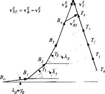
(For a discussion of differential and relative velocities, refer back to Example 4.17). The Earth serves here as an inertial frame. As long as the relative velocity vector is pointing at the target, i. e., parallel to the LOS, an intercept will occur (assuming constant velocities). This engagement triangle is shown in Fig. 9.21. Although it is valid in three dimensions, let us consider it from a two-dimensional standpoint. The flight-path angle у and the LOS angle к are defined wrt an inertial datum. These angles must remain constant for the intercept. If the target maneuvers evasively, the missile velocity vector must be adjusted according to the change in LOS angle. For instance, if the target speeds up, к increases, and, therefore, у must be increased in order to maintain the engagement triangle. In other words, the time rate of change of у must be made proportional to the time rate of change of k, i. e.,

у = Nk (9.52)

with the navigation ratio N as the proportionality constant. Equation (9.52) is the famous PN relationship. The navigation ratio determines the lead of the missile velocity vector wrt the target. For most missiles it is given the value between two and four. Modern optimal control assigns it the value three.16

Let us look at Fig. 9.22 and follow an engagement that starts outside the engage­ment triangle. Assume that missile and target velocities are constant. Initially, the missile Bq flies directly toward the target To, and the glide-path angle yo equals the LOS angle ко – The advancing target turns the LOS and generates a k, which, magnified by N, turns the missile by у. Now, y > k, and the missile’s flight-path

Intercept

Proportional navigation

Fig. 9.22 Engagement starting from arbitrary initial conditions.

angle starts to lead the LOS angle. Eventually, the engagement triangle does not change shape and A = 0, у = 0 until intercept.

In applications the LOS rate A is measured by the missile seeker and converted through the PN law into the acceleration command for the autopilot. The missing link is the relationship between у and acceleration a. We derive it from the fact that the acceleration normal to the missile velocity vector vf is (with V = |i>f |)

a = Vy (9.53)

and we obtain with Eq. (9.52) the steering command for the autopilot

a = NVA (9.54)

This relationship applies only to planar engagements. The extension to the three – dimensional case follows by similitude. The angular velocity vector of the LOS frame О wrt the inertial Earth frame E is ш0Е, and the angular velocity vector of the velocity vector vf wrt Earth is u>VE. Following Eq. (9.52), we formulate in three dimensions

uVE = Nujoe (9.55)

Furthermore, taking our cue from Eq. (9.53), the acceleration a normal to the missile velocity is proportional to the cross product of uiVE and the unit vector u, ofvf:

a = VflVEuv (9.56)

Substituting Eq. (9.55) into the last relationship yields the acceleration command

a = NVCl0Euv — g (9.57)

with the added gravity bias term g. Without this term and no signal from the seeker, zero acceleration would be commanded, resulting in a ballistic trajectory.

The g-bias term counteracts the sagging tendency of the trajectory under seeker control.

This form of PN has been given the special designation pure PN19 and is charac­terized by the fact that the acceleration command is normal to the inertial missile velocity vector vf. Another form, the so-called true PN,19 generates its accelera­tion command normal to the relative velocity vector vfr. It has the same form as pure PN, portrayed in Eq. (9.57), except that uv is taken as the unit vector of vfr and V = |ufr|.

Let us pause, sit back, and look at the effect that a rotating round Earth can have on the PN implementation. Certainly, the angular velocity of the Earth is negligible wrt the rapidly changing LOS rate of a missile engagement. Therefore, the preceding equations are equally valid for the rotating Earth case.

For practical applications the inertial LOS rates ш0Е and the unit velocity vector are given in body axes, whereas the gravity bias is expressed in local-level axes (or geographic axes for round-rotating Earth). The acceleration command to the autopilot must be delivered in body axes:

[a]B = NV[n0E]B[uv}B – [T]BL[g]L (9.58)

Full information awareness is assumed. The INS provides [T]BL. The seeker deliv­ers [w0E]B and, in addition, [uv]B fortrue PN. Some simplifications are possible. If the acceleration levels of the engagements are high, like in close-in combat, gravity can be neglected, and therefore [T]BL is not needed. Infrared imaging seekers do not deliver full target-missile kinematics as radio frequency seekers do. Therefore, if the relative LOS vector cannot be constructed, pure PN is implemented and [uv]B calculated from INS data.

Guidance

First, let us attempt a definition: Guidance is the logic that issues steering com­mands to the vehicle to accomplish certain flight objectives. For a missile the objective may be to hit a target. Given the vehicle and target states—position, velocity, and angles—the guidance algorithm generates the autopilot commands that steer the missile to the target.

For an aircraft on final approach, the objective is the descent on a glide slope leading to the touchdown point on the runway. If the pilot is at the controls, he issues the steering commands directly to the fin actuators, based on the situational awareness presented to him by the cockpit instruments. He fulfills the function of the guidance logic and the autopilot. Alternatively, if a stability augmentation system is engaged, he sends via his stick guidance signals to the autopilot. In the case of an automatic landing system, the electronics take over completely and provide the guidance logic for a hands-off touchdown.

Dealing with unmanned vehicles, like missiles and projectiles, the guidance logic is the most important function for ensuring mission success. Therefore, it is imbued with particular stature and is called the guidance law. You have probably heard about the proportional navigation law, which more appropriately should be called proportional guidance law. Some of its prefixes indicate performance improvements, like augmented, higher order, etc. Other guidance laws have names like line guidance, parabolic guidance, squint angle guidance, and others.

The open literature does not cover all aspects of guidance because some of the tricks of this trade are either classified or proprietary to industry. However, a few good references have been published just recently. Advances in Missile Guidance Theory by Ben-Asher13 addresses guidance from a modern control as­pect. An easier text to read is the third edition by Zarchan Tactical and Strategic Missile Guidance.14 Practical guidance aspects are provided in Modem Naviga­tion Guidance, and Control Processing by Lin.15 Also many of us owe much insight into optimal guidance to Bryson and Ho and their classic Applied Optimal Control.16

For our simplified five-DoF representation of missiles and aircraft, I will limit the discussion to the basic, but all-pervasive proportional navigation law for missiles, and to line guidance, suitable for way-point guidance or landing approaches. Some of the more advanced schemes are introduced in conjunction with the full six-DoF simulations (see Chapter 10).

Although we live in this chapter in the pseudo-five-DoF world, with its special autopilot provisions, the guidance loop (outer feedback loop) is affected little by these simplifications. This fact is useful in two ways. During the conceptual phase of a vehicle design, detailed guidance studies can be conducted without detailed knowledge of aerodynamic and autopilot specifications. Alternately, if a full six-DoF simulation must be simplified, e. g., shortening run time by simplifying aerodynamics and reducing the autopilot bandwidth, the guidance loop can be transferred directly to the pseudo-five-DoF implementation.

Altitude hold autopilot

There is little difference between a five – and six-DoF altitude hold autopilot. Two feedback loops are wrapped around the acceleration autopilot (see Fig. 9.18) with two gains G# and Gy determining the dynamic response. To prevent large error signals driving the acceleration loop, I inserted an altitude rate limiter HDTLIM. The measured signals are altitude rate from the INS and altitude from an altimeter. According to our pseudo-five-DoF approach, the acceleration autopilot provides the angle of attack that is needed in the aerodynamic table look-up routines. The airframe block provides the remaining dynamics and measurements.

Let us address the need for the gravity bias term. When the vehicle flies straight and level, the altitude error signal is zero. However, to counteract gravity the airframe must generate a 1 – g load factor. This commanded input is provided by the gravity bias term.

We have to distinguish between the implementations for skid-to-tum and bank – to-turn vehicle. While the altitude controller operates in the vertical plane, the

НПТІ. Ш Gravity bias

Подпись: Acceleration Autopilot Подпись: Airframea

I____ Altitude rate feedback

Altitude feeback_____________________________________

Altitude hold autopilot
Подпись: ► COS <j>By

Fig. 9.19 Altitude hold autopilot for bank-to-turn and skid-to-turn vehicles.

pitch plane of the vehicle can be banked through the angle фву – The adjustments through cos фву are shown in Fig. 9.19, as well as the two integrations that convert the vertical acceleration ay into altitude rate and altitude. If фву = 0, the vehicle executes skid-to-turn maneuvers and cos фву = 1 ■

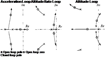
To determine the gains G# and Gy, we start first with the design of the accel­eration autopilot followed by a root locus analysis of the inner and outer altitude loops. Figure 9.20 shows the root locus patterns. The complete altitude hold loop has five closed-loop poles with a dominant oscillatory complex conjugate pair. For the CRUISE5 concept I selected the constant values

Gh = 0.5, Gv = 1, HDTLIM = 20 m/s

They give good performance also for terrain following and obstacle avoidance flights.

Подпись: Acceleration Loop Altitude Rate Loop Altitude Loop x Open loop pole о Open loop zero Closed loop pole

We will stop here. You may require other autopilot functions for your specific vehicles, but I hope that these three examples, illustrating the idiosyncrasy of pseudo-five-DoF simulations, will enable you to devise your own designs. On the CAD AC CD you will find several other options like flight-path-angle hold, thrust vector pointing for reentry vehicles, yaw and pitch rate hold, etc. Look up the FORTRAN code and see if any one suits your applications.

Вапк-to-turn autopilot

As you know, the yawing degree of free­dom is neglected in five-DoF aircraft simulations by enforcing zero sideslip. This corresponds to the assumption of perfectly coordinated bank-to-turn maneuvers. Let us make use of this simplification and build a basic bank-to-tum autopilot.

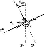
We maintain the acceleration feedback channel in the pitch plane. However, this body-fixed plane is now rotated about the velocity vector through the bank angle <Pbv wrt the vertical plane (see Fig. 9.16). The lateral acceleration is, given the normal load a^,

aL=aNsin<pBV (9.49)

Вапк-to-turn autopilot

Fig. 9.16 Banking aircraft.

To maintain the same maneuver direction under negative angle of attack, the aircraft must bank in the opposite direction. We see that we must build into the banking logic a switching function that is dependent on the normal load factor sign. Figure 9.17 exhibits the autopilot embedded in a bank-to-tum vehicle. The pitch acceleration feedback autopilot is carried over unaltered from Fig. 9.15. The lateral acceleration command, beyond a small threshold, is divided by the normal load factor, given the correct sign, and limited in magnitude. Now we represent the roll degree of freedom by a simple first-order transfer function (remember our pseudo – five-DoF approach). You should get the value of its time constant Тф from a six-DoF simulation, possibly making it a function of dynamic pressure. Most likely, the six – DoF simulation has a closed-loop roll transfer function of second order. If it is opti­mally damped (f = 0.7), then the time constant of the first-order approximation is

1

ф 0.707co„

where con is the natural frequency. This converts for a roll autopilot with position and rate feedback to

Тф qSl Kp{Ch-[l/(2Vmp} (9’50)

with Ip the roll moment of inertia, Kp the inner roll rate gain, C;s and С/ the roll control and damping derivatives, respectively. The details are not as important as the facts that the roll time constant increases with moment of inertia and decreases with dynamic pressure.

Вапк-to-turn autopilot

Finally, to establish the lateral acceleration aL, the achieved bank angle is mul­tiplied by aN.

For the bank-to-tum autopilot the acceleration command a;v must be given in the normal load factor plane of the aircraft. More frequently, the guidance command will be expressed in the vertical plane. This poses no problem for the skid-to-tum vehicle. However, for bank-to-tum implementations we have to convert it first by dividing it by the bank angle cos фву.

I have to confess to a simplification that I have glossed over so far. The roll DoF in a six-DoF simulation is with respect to the body 1 axis. On the other hand, the bank angle in a five-DoF simulation is about the velocity vector. The two axes differ by the angle of attack. Strictly speaking, the first-order lag in Fig. 9.17 is the representation of the roll loop response, but we interpret it as the bank angle DoF. The effect is negligible, particularly because the angle of attack of bank-to-tum vehicles is usually less than 10 deg.

You can find the details of the implementation of Fig. 9.17 in the cruise missile simulation CAD AC CRUISE5. The gain Gcp could have the value one but is usually increased to two or three to counteract the flattening of the sin <pc curve. To prevent division by zero, I added the small bias of 0.001 to the denominator. The threshold prevents roll oscillations under noisy lateral acceleration commands. A typical value of the threshold is 0.0174 g.

This bank-to-turn autopilot applies to aircraft, cmise missiles, hypersonic planar configured vehicles, and ramjet-powered missiles. If the vehicle cmises for any length of time, it may have to maintain altitude. We now modify the pitch channel to introduce altitude feedback.

Acceleration controller

Let us start with the heart of a missile autopilot. It consists of body rate and acceleration feedback with lead/lag shaping filters as depicted in Fig. 9.9. For five-DoF modeling we simply represent the rate feedback loop by a first-order transfer function with the time constant TR, which is representative of the full rate autopilot response. If the flight conditions are changing dramatically, you should consider making the value of TR a function of dynamic pressure.

How can we generate the angle of attack from the output of the rate loop? We make use of the incidence-lag relationship. Consider Fig. 9.10 with its lift force L and thrust F. and apply Newton’s second law in the direction normal to the velocity vector v £:

mV у = Fa + qSCRact (9.38)

where we approximated the lift coefficient by its slope CR = CRaoi and assumed

Acceleration controller

small incidence angles. Taking the time derivative of the angular relationship

а — в — y=q — у (9.39)

Acceleration controller Подпись: (9.40)

and substituting it into Eq. (9.38) yields the incidence-lag differential equation

Acceleration controller Подпись: (9.41)

with the time constant

and the Laplace transfer function of angle of attack wrt pitch-rate response

Подпись: (9.42)Ф) _ T

q(s) Tts + 1

The value of the incidence-lag time constant 7} decreases with increasing lift and thrust, reflecting the improved responsiveness of the airframe. For accurate modeling the lift slope coefficient CLa should be made a function of Mach number and possibly of angle of attack.

The airframe block in Fig. 9.9 represents Newton’s equations with the aerody­namic and thrust tables providing the specific forces. Accelerometers, nowadays located in the IMU, measure the accelerations. To keep the simulation simple, higher-order sensor dynamics are neglected.

As an example, I use the acceleration feedback autopilot of the CADAC SRAAM5 simulation. Its position in the logic flow is shown in Fig. 9.11. The guidance module sends the pitch and yaw acceleration commands a^c and au, respectively, to the autopilot, and the measured acceleration [/sp]B comes from the INS. Rocket thrust F is needed for the 7} calculation. The output, incidence angles a and /1, is transmitted to the aerodynamic tables.

Acceleration controller

The block diagrams, Figs. 9.12 and 9.13, show in greater detail the actual im­plementation of the pitch and yaw loops. They are very similar, but watch out for the signs (they have been the nemesis of many student projects). We are following the sign conventions of missile aerodynamics. Normal acceleration is positive up and lateral acceleration positive to the right. Pitch rate q, positive up, produces positive a, but yaw rate r, positive to the right, generates negative fi.

Acceleration controller

Fig. 9.12 Pitch acceleration loop.

The acceleration command, by convention in gs, is converted—after limiting— to the units meters/seconds squared. The error signal is fed through a proportional gain Gr and, for tracking accuracy, through an integrator with gain Gj. After the rate-loop and the incidence-lag transfer functions, the incidence angle is limited before being sent to the aerodynamic tables.

This autopilot must control the vehicle throughout its expansive flight envelope. For air-to-air missiles the excursions are from subsonic launch to triple the sonic speed at motor burnout; incidence angles may reach 50 deg; and the dynamic pressure can change by a factor of 20. Gain scheduling of Gr and G/ provides this flexibility, given the representative time constant TR of the body-rate feedback loop.

The rate loop transfer function is based on the simplified moment equation about the c. m.

Iq = qSlCms8 (9.43)

with I the moment of inertia, l the moment reference length, 8 the control fin deflection, and Cms the control moment derivative. Figure 9.14 depicts the rate feedback loop for the pitch plane. You should be able to produce the equivalent yaw loop. Ga is the rate loop gain that converts the error signal into a control deflection, followed by the control limiter, the control effectiveness term, and the inertial integrator. The two negative signs are introduced to abide by the aerodynamic convention that a positive control deflection generates a negative pitch rate, but because they cancel, they are of no consequence.

Acceleration controller

Подпись: Fig. 9.14 Rate feedback loop for pitch control.
Подпись: TR Acceleration controller Подпись: (9.44)

The closed-loop transfer function is of first order with the gain of one and the time constant

Note that the time constant is inversely proportional to the dynamic pressure and the open loop gain GA ■ Its values should be taken from response curves of six-DoF simulations and expressed as a function of q. The CADAC SRAAM5 simulation uses the simple linear relationship Tr = 0.22 — 2 x Q~7 q based on the six-DoF CADAC SRAAM6 data.

I recommend that you use the following root locus technique to calculate the GR and G/ gain scheduling. But first, we have to complete the acceleration feedback loop of Fig. 9.9 by providing the transfer function for the airframe.

Подпись: a Acceleration controller Подпись: (9.45)

Refer back to Eq. (9.38) and recognize that the acceleration normal to the velocity vector is a = Vy. Then, with the definition of the incidence-lag time constant 7) of Eq. (9.41)

and the complete acceleration loop is shown in Fig. 9.15. The open-loop transfer function for the root locus procedure is

Ф) ^ (s + l/TA)

—~7 = IJACP— I v , , ■ (9.46)

£(5-) j(j+ l/7»(s + 1/7-)

with the root locus gain GACp = GRV/(TRTi) and lead time constant TA — Gr/G[. The root locus emanates from the three poles and terminates at the zero and at infinity along two vertical asymptotes.

Acceleration controller

I picked the gain Gacp = 12.2 with the closed-loop roots —2.7525 + 2.7689/, —2.7525 — 2.7689/, —0.6670 for best performance resulting in GR = 0.0055 and Gi = 0.0046. This type of analysis, applied throughout the flight envelope, gave me the gain schedule Gacp = (0.002q)°-575 and constant TA = 1.2 (see CADAC SRAAM5 simulation).

If the rate loop time constant Tr is not known, a simplified analysis can guide us to select appropriate values. We first develop the transfer function 8(s)/ac(s), then impose the initial value theorem for step input, and finally obtain the relationship

го _ G,GAcpTRTi ^

ac( step) У

Acceleration controller Подпись: (9.48)

The initial fin deflection So, which is also the maximum deflection, is proportional to an acceleration step input aC(step), related by the gains GA and Gacp and the time constants Tr, Tj. Given the maximum control fin deflection and the desired maxi­mum acceleration capability, Eq. (9.47) can be evaluated. However, GA and Gacp are also not known prior to the root locus analysis. Therefore, we have to employ an iterative design technique: Assume a value for TR, conduct the root locus analysis, and verify that the desired acceleration can be achieved. Substituting into Eq. (9.47) the expressions for Tr, Tt, Eqs. (9.44) and (9.41), and solving for ac yields

Note that the dependence on the rate gain GA cancels. Given the maximum control deflection, the achievable acceleration increases with increasing dynamic pressure, thrust, aerodynamic lift slope, and control derivative; and decreases with increas­ing mass properties. A high value of the root locus gain Gacp is also desirable, but must be balanced against the stability requirements.

The acceleration feedback autopilot with inner-rate-loop stabilization finds widespread application in missiles. Its feedback signals are readily obtained from the onboard IMU, and its command signal is directly supplied by the guidance law. On the other hand, angle-of-attack feedback autopilots are also sometimes employed, particularly for high angle-of-attack maneuvers when tight incidence angle control is required. In aircraft angle-of-attack, sensors may be available, but for missiles the feedback signal must be synthesized from IMU measurements and may, therefore, lack accuracy.

Congratulations, you have persevered through the labyrinth of autopilot design for skid-to-tum missiles. But what if you have to model a cruise missile or a bank – to-tum hypersonic vehicle? I will lead you through the steps to modify what you have learned and combine it with a bank-to-tum controller.

Autopilot

When the Wright brothers flew their first contraption, they controlled the air­frame with stick and rudder. Manually they counteracted wind gusts and steered the plane on its course. By the end of World War II, the flying machines became so sophisticated that the pilot needed some help from electronic instruments. For sim­ple flight conditions, like steady cruise over long distances, the electronics would take over completely, and with hands off, the automatic pilot would control the aircraft. Today, autopilots are found in every aircraft. Missiles, lacking the human touch, cannot fly without them. We are even now conceptualizing combat aircraft that relegate the pilot to a ground controller,

There are many good references on control theory in general and autopilots in particular. A good introduction to classical and modern control is the textbook by Dorf and Bishop,9 which uses the popular MATLAB®10 software package. Pamadi7 treats flight controllers from a classical viewpoint, whereas Steven and Lewis6 approach them from a modem angle. One of my favorite books on advanced topics is by Stengel11 addressing the stochastic effects of control. If you are fluent in German, you should consider the standard text by Brockhaus.12

Autopilots stabilize airframes, improve control response, convert guidance sig­nals to actuator commands, and maintain constant flight parameters. They compare the commanded inputs with the measured states and shape the error signal for exe­cution by the actuators. Figure 9.8 shows the position of the autopilot for a piloted

Autopilot

Lead/Lag 1 L

PI, PID V+l 7> + l

Autopilot

Fig. 9.9 Pseudo-five-DoF pitch plane acceleration controller for missiles (similar for yaw plane).

aircraft (inner loop only) and for a missile (inner loop with guiding outer loop). For an aircraft the pilot sets the course; for a missile the goal is to reach a certain target state, be it for intercept, rendezvous, or specific end conditions.

The signal of the feedback loop determines the type of autopilot. A flight-path controller operates on flight-path-angle measurements. In the horizontal plane it is also referred to as heading autopilot. To hold altitude, height measurements are used in the altitude controller. A bank-angle controller executes constant turns. For missiles the acceleration controllers are particularly important because the commands from the guidance system are expressed in body accelerations.

Propulsion

Most of our needs for modeling thrust forces have already been covered in Sec. 8.2.4. The equations for rockets and combined-cycle airbreathing engines apply here as well. I will only expand on turbojet propulsion because it plays such an important role in cruise missiles and aircraft.

Review the section on turbojet propulsion in Chapter 8. The thrust formula

F = ma(Ve – V) (9.36)

(with V as the flight velocity, Ve the exhaust velocity, and ma the airflow rate) is commonly replaced by tables for thrust, fuel flow, and dynamic transients. We will work through an example that is used for cruise missiles and aircraft.

Propulsion

Fig. 9.6 Mach hold control loop.


Cruise missiles have to maintain Mach number under maneuvers and environ­mental effects. Particularly challenging are the terrain-following and obstacle- avoidance flight patterns. We will model a Mach-number hold system suitable for cruise missiles and aircraft under such conditions.

The thrust required Fr to maintain a certain Mach number is equal to the drag force projected onto the centerline of the turbine. If the turbine axis is parallel to the body 1 axis, we require that

Подпись: (9.37)qSCp cos a

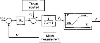
This value is used in the Mach hold control loop of Fig. 9.6. The commanded Mach number Mc is compared with the measured value M, and the difference is sent through a gain Gm that changes units to Newtons. The demanded thrust Fc is realized by the turbojet after spool-up or spool-down delays, characterized by the first-order lag time constant 7>. However, it may exceed the maximum possible thrust or drop below the idle thrust. Limiting tables restrict this excess demand. They are, in general, functions of Mach number and altitude. In simulations, the achieved thrust F is added to the right-hand side of Newton’s dynamic equations.

Propulsion

The time constant 7> and the gain G ц are possibly a function of power setting. As an example, the spool-up time constant for the Falcon turbojet engine FI 00- PW-200 is between 7> = 0.2 —► 1.0 s. The gain can be calculated from a simple transfer function. We complete the control loop of Fig. 9.6 by the vehicle transfer functions, represented by the vehicle mass m B, an integrator, and the conversion to Mach number by the sonic speed Vs (see Fig. 9.7). The closed-loop transfer function is of second degree, characterized by the natural frequency oj„ and damping f. We

can eliminate con and solve for the gain

mB Vs

°M = 4W2

With Tf = 0.2 s given and f = 0.707 selected, the value for the Falcon is Gм =

3.4 x 10⁶.

Once the thrust F of the turbojet is given, we only have to determine the mass of the vehicle from the fuel consumed and the initial gross weight. The specific fuel consumption bf serves this purpose. It is usually given in tabular form as a function of Mach number and altitude. Multiplied by the thrust, it provides the fuel flow, which, integrated over time, supplies the expended fuel.

You can find the details of the implementation in the five-DoF cruise missile simulation CADAC CRUISE5 and the six-DoF simulation CADAC FALCON6. The engine decks are provided in English units, just to keep your unit conversion skills sharp.