Category NEW DESIGN CONCEPTS FOR HIGH SPEED AIR TRANSPORT

THE OBLIQUE FLYING WING TRANSPORT

A. Van der Velden
Synaps Inc., Atlanta, GA, USA

19.1 Introduction

in the last thirty-five year» there have been numerous attempts to design an economical large long range supersonic transport aircraft. However, aircraft design teams around the world have not been successful at designing a ‘Concorde’ type large long range supersonic transport with real­istic technology assumptions. It therefore seems only natural to look for other configurations that might fullfil this specification The oblique flying wing configuration presented in this paper is unusual but we will show that it makes sense from both a technical and economical perspective.

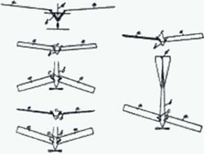
Figure 115 shows the first oblique wing design. It was proposed by two Frenchmen. Edmond de Marcay and Emile Moonen around 1912 [402). They saw the oblique position of the wing as a means to land the low speed aircraft of their time in the presence of crosswind without sideslipping the wing. In the decades to follow oblique wings were used to simulate sideslip in a windtunncl. It was not until 1943*1944 that engineers at Mcsscrschmitt and Blohm & Voss combined the newly discovered phenomena of high speed drag reduction and wing sweep with the ‘old’ sideslipping wing. After WWII Richard Vogt of Blohm & Voss showed the oblique wing designs to R. T. Jones of NACA. Dr. Jones became convinced of the merits of this configu­ration and has actively pursued it until today During the 1960’s and 1970’s he convinced many engineers at NASA. Boeing and Rockwell to study this exotic aircraft.

Figure 115 First Oblique Wing Design (Courtesy: Steve Ransom)

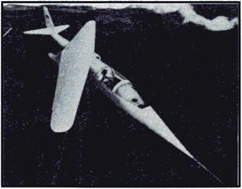
Figure 116 shows the AD-1 the first full scale oblique wing aircraft designed by Burt Rutan. On the 21 December 1979 the AD-1 this aircraft made its first flight. Though the oblique wing-body was a success from a controls and aerodynamics point of view, it had poor structural qualities. The increase in structural weight due to the routing of the loads through the center pivot was not offset by the high-speed drag reduction.

Figure 116 AD-1 by Rutan (1979>

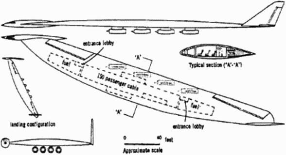
In 1958, R. T. Jones and Lee of Handley Page (399) had proposed an even radical design that could overcome the high structural weight of the oblique wing body concept. Even though the design shown in Figure 117 was considered interesting, few have researched it since it was first proposed.

Figure 117 Lee’s Slewed Wing Transport Proposal (1961)

The only research on this configuration – as known to the author – was done by Smith

[401] in the U. K. and R. T. Jones in the U. S.A. As shown, the aircraft cannot be controlled due to its aft center of gravity position, even with todays artitical stabiliration technology. Because the payload does not efficiently fit the available volume, the aircraft is too small for efficient super – some flight. As a consequence the configuration of Figure 117 was in many ways inferior to the Concorde, as Dr. Kuchemann [398] correctly predicted at the time.

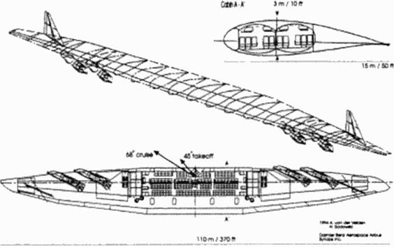
In 1987 Dr. Jones [397] and the author (403J proposed a new oblique flying wing design that takes advantage of the controls and oblique w ing knowledge accumulated in the lost four decades. In the last eight years we have learned far more about the design, but its basic lay­out has remained nearly unchanged. Figure 118 shows the latest version of the design. The present paper describes the state of the an of this oblique flying wing configuration and is largely based on the author’s PhD thesis [405) at Stanford University.

Figure 118 Jones’ and Van der Velden’s concept 1987 . 1994

Supersonic Laminar Flow Flight Tests

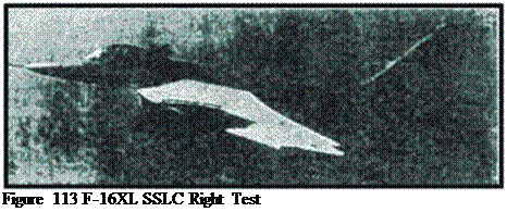
At NASA-Langley an F-I6XL was modified for supersonic laminar flow investigations (F – 16XL SSLFC. Figure 113). A glove with suction was designed (3931 and applied to the aircraft. It was flown with successful laminarisation by suction behind a round subsonic leading edge at supersonic speeds (394). But apparently laminar flow was realized only in dive (at no lift) con­ditions. and there are difficulties in understanding the results and in validating the methods used

Подпись: Figure 113 F-16XL SSLC Right Test

The reason seems to be insufficient resolution of the boundary layer profiles in the solution of the undisturbed flow, including ihc second derivatives (ca. 20 points in the boundary layer nor­mal to the surface instead of about 80 required). Nevertheless, a suction system able to provide laminar flow at supersonic flight was demonstrated.

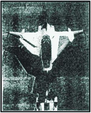
Since then a second flight test scries with the F-I6XL SSLFC was planned using two different new glove designs for the right and left hand wing (Figure 114) [395] and completed 1396).

Подпись:F-16XL SSLFC with Two Gloves

In any case, flight experiments arc essential for validation of laminarisation technol­ogy. They cannot completely be replaced by ground tests. Due to high cost they should be lim­ited to a minimum. This may become possible by improvements in theory and ground test facilities, but some validation flight tests will remain essential.

18.5 Conclusion

Laminarisation is a promising technology for future Supersonic Commercial Transports. First in­vestigations indicate significant improvements of aircraft efficiency.

Theoretical prediction of the transition laminarAurbulent requires substantially improved CFD-solulions of the undisturbed 3D-flow.

Stability analysis itself must be improved to describe coupling of different instabilities (CFI and TS1), but also to respect for non-adiabatic walls and HMI.

A quiet Ludwicg tube for Mach 16 to 2.4 and high Reynolds number (RcL ca. 300 Mio) should be used in Europe to allow for high quality ground based check experiments

A new design approach must be developed, based mainly on

• theoretical predictions

• and partial simulation by turbulent tests in classical supersonic wind tunnels

• but it must rely on selected checks in a quiet high Reynolds ground test facility

• and validation by carefully designed flight tests.

Wind Tunnels for Supersonic Laminar Flow

ALT and CFI arc not very sensitive to disturbances of the incoming flow or noise radiation (table 3). So. classical wind tunnels should be suitable for investigations. But at the high sweep angles of subsonic leading edges massive suction is required (at high model Reynolds numbers up to 300 Mio). Suction flow cannot be simulated in the wind tunnel, at least not for complete aircraft models: The hole diameter in the suction surfaces is at the limits of manufacture, hole diameter cannot be reduced according to model scale; this violates the model laws. This violation becomes important, when the hole diameter is not small compared to the local boundary layer thickness. For SCT-applications, the hole diameter at the leading edge of the flying aircraft is about the boundary layer thickness. Suction simulation on aircraft models is therefore impossible, at least in the vicinity of the leading edge.

Подпись: ALT, CFI: classical supersonic wind tunnels, comparable to transonic aircraft; but massive suction is required for high sweep angles TSI: + sensitive to external disturbances (W/T noise, W/T turbulence) + high Reynolds numbers required (up to 300 Mio model Re) + cooled boundary layers => temperature simulation (TSI stabilized by cooling, HMI destabilized)

Table 3: Wind Tunnel Simulation

TSI are very sensitive to external disturbances. For supersonic wind tunnels these arc the turbulence of the incoming flow (as for subsonic wind tunnels). Also, strong noise is radi­ated into the test section. It is – by one part – produced by upstream noise radiated via the reser­voir section, e g. valve noise in blow down tunnels But the most severe pan is boundary layer noise radiated by the turbulent boundary layer of the wind tunnel nozzle into the lest section: Each turbulent eddy in the outer boundary layer produces a small shock wave on its back which radiates a strong noise in Mach line direction. This provokes premature transition, so that effec­tively transition in supersonic wind tunnels scams to be dependent on nozzle Reynolds number instead of the model Reynolds number, the so called unit Reynolds number effect.

Furthermore, in most supersonic wind tunnels the attainable Reynolds numbers are completely insufficient. Often they arc so low, that after provoked transition (tripping) relami – narisation occurs (389). The cruise Reynolds numbers for supersonic transpons arc about Ret = 300 Millions with respect to the aircraft length L!

In the past, surface temperature of supersonic wind tunnel models was not taken into account For investigation of TSI (and HMI). accurate simulation of the temperature profile in

the boundary layer is necessary, i. e. the ratio of model wall temperature to stagnation tempera­ture must be simulated.

To enable supersonic transition measurements, a quiet supersonic wind tunnel was developed at NASA-Langlcy (Figure 111) (390]. It is a small pilot tunnel for Mach 3.5:

Подпись: Flow

In the subsonic part of the nozzle throat the boundary layer is removed to provide a young lami­nar boundary layer in the wind tunnel nozzle. This laminar boundary layer does not radiate sig­nificant noise into the test section. When the nozzle boundary layer becomes turbulent, noise is radiated. But in supersonic flow this noise follows characteristics (Mach lines). So a quiet test zone is provided, beginning with the parallel flow section and ending with the characteristics of the nozzle transition zone. This wind tunnel provided transition measurement results compara­ble to flight tests.

Quiet
test core

Figure 111 Quiet Supersonic Wind Tunnel

Another wind tunnel provided test data not showing the unit Re-cfTect: this was the Ludwieg tube in Gdtlingcn (391J with measurements at Mach 5 (Figure 112) (392). The reason for these high quality measurements is not completely understood: The Ludwieg tube provides an incoming flow of extremely low turbulence, but the wind tunnel nozzle has a turbulent boundary layer of high nozzle Reynolds number, i. e. with small boundary layer thickness and – perhaps – not so disturbing noise levels and spectra.

no unit Ri ■ «*Чсі round kx Т» CMг««п. л).*; to* и » Si

Figure 112 Ludwieg Tube

Wilh respect to future supersonic laminar flow experiments, the Ludwieg principle should be considered in Europe, possibly with a quiet nozzle – like in the US. where Ludwieg tubes are designed for SCT-tests. Some advantages arc obvious:

• superb flow quality,

• high Reynolds numbers possible (about 300 Mio),

• quiet nozzle design easier at short testing times,

• model cooling easier for short testing times.

• low costs, affordable in Europe,

• but low productivity (about 0.5 s run time).

For the latter this test facility will not be suited for standard development tests, but rather for high performance quality checks. A suited Ludwieg tube (today Mach numbers 1.75 and 2.5; size more than 1 m diameter) exists at the University of Stuttgart and was refurbished in the past years.

Considering these facts, a new procedure for aircraft design must be developed. It relies more on theoretical predictions, partial simulation tests in classical wind tunnels (i. c. model tests with turbulent flow) and very carefully selected checks in the high quality Ludwieg tube, mostly to evaluate transition physics in validation experiments. Comparable procedures were developed for reentry vehicles like Hermes: Partial simulation is used, a relatively small number of experimental checks, and it relics strongly on theoretical predictions.

Theoretical Prediction of Supersonic Transition

ALT is predicted by the Pfenningcr/Poll criterion [380).(3811 which is assumed to be valid at su­personic speeds (Table 2). but confirmation at the Mach numbers of interest is missing. Means to avoid ALT can be transposed from subsonic knowledge. Additional investigations are still strongly appreciated: because it is still a big challenge to design and manufacture a subsonic lead­ing edge for high aerodynamic performance at cruise and take-off which avoids ALT and is able to control CF1 by suction.

ALT. Attachmcni Line Transition CF1: Cross Row Instability

ALT:

Pfenmnger / Poll criterion, as for subsonics

CF1, TSI:

+ strongly 3D

+ coupling of CFI and TSI

+ temperature profile (cooling)

♦ higher mode instabilities (HMI)

Required:

+ improved linearized theory Cc*’)

+ improved analysis (PSE, DNS)

+ accurate 3D<solution of undisturbed flow

TSI: Totlmicn-Schlichting-lnstability

HMI: Higher Mode Instabilities

Tabic 2: Transition Effects and Prediction

СП, TSI and HMI are predicted by stability analysis of the boundary-layer flow distur­bances.

Linearized theory ("eN") has matured and can be used routinely, even for supersonic investigations [382J. if cooled surfaces and HMI are respected. Linearized theory solves the flow equations by superposition of two parts (383):

• undisturbed flow.

• small disturbance of one disturbance mode.

(one frequency resp. one wave length at one inclination to the flow direction).

Because the disturbances arc small, linearisation is allowed Eventually, it is possible to dense a pure local disturbance equation formulation, where at one position the disturbance equations are solved only in normal position to the wall. Resulting is the local amplification rate for the selected disturbance mode at this position. Total amplification rate is achieved by the fol­lowing procedure:

First, search for a point of indifference, where amplification rate is zero. i. e. it changes from damping to amplification. Stoning from this point, follow a suited integration line (down­stream). c. g. a stream line (of the "inviscid" flow). Integrate along this (stream) line the local amplification rates for the selected disturbance mode (which may change from point to point, depending on the selected integration strategy). When writing the integrated amplification rate A in exponential form

A = e

N = /n(A) becomes the so called N-factor. So, the result of linearized theory is an amplification rate, but not the disturbance itself. Therefore, transition prediction requires a vali­dation by transition tests in order to calibrate a relevant amplification rate. This calibration may depend on the environment (free flight, wind tunnel, external disturbances like turbulence, noise; internal disturbances like roughness, waviness, surface vibrations). The often cited limit N-factor of about 10 is restricted to specific calculation methods (incl. the selected boundary – layer codes) and applications; (some people suggest, that 10 was only detected, because we have 10 fingers…)

By definition, linearized theory cannot calculate

• changes of the undisturbed flow introduced by the disturbances

• interferencies of different amplification modes

• sensitivity of transition to external or internal disturbances (so-called receptivity).

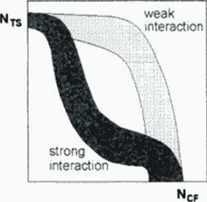
The limitations of linearized theory become increasingly obvious (Figure 110): More or less strong coupling of CFI and TSI may occur. The correlation figures for both cases arc completely different and. maybe, the whole zone in between can become valid. Additional effects like curvature and boundary layer divergence must be respected; hitherto especially the latter is not taken into account and may be responsible for some confusing results. Also, validity of linearized theory for CF1 is questioned (384). especially for strong CFI like on SCT-wings In supersonic flow, the TSI-waves are not normal to the flow direction, but inclined as nearly by the Mach angle. So coupling between TS1 and CFI may increase.

Figure 110 for Transition Prediction

Furthermore, linearized theory calculates only amplification rates (N-factors) which require validation by experiments, but ground test facilities for supersonic transition tests still do not exist.

A remedy is seen in Parabolized Stability Equations (PSE) (385) which arc able to han­dle coupling of CFI and TSI and – perhaps – to investigate the receptivity problem (386). (387). The latter must be solved to understand the supersonic wind tunnel simulation problem.

Analytical approaches were limited to very special problems.

For insight in the complicated flow physics and for calibration of the simplified meth­ods further investigations with Direct Numerical Simulation (DNS) – see e. g. (388) – is required.

For all engineering methods (linearized or parabolized disturbance theories) a prereq­uisite is the accurate solution of the undisturbed flow. It requires solution of the boundary layer profile for velocities and temperatures in both directions, accurate in the second derivatives. This is. for the years to come, the most severe task on strongly 3D flows.

Supersonic Transition Physics

At the subsonic leading edges of the inner part of the wing. Attachment Line Transition (ALT) occurs as known from subsonic transports (Figure 109). It develops because on swept wings the flow at the attachment line does not start its contact with the surface there (with local Reynolds

number zero), but follows the attachment line and splits the flow to the upper and lower side of the wmg. For infinite swept wings a boundary-layer develops at the attachment line which is in an equilibrium between boundary layer material advected along the attachment line (increasing boundary-layer mass) and divergent flow by the removal of mass over the wing (reducing bound­ary-layer mass).

supersorwc leading edge

Figure 109 Transition Types

Downstiearn the round leading edge a strongly three dimensional flow region produces Cross Flow Instabilities (CFI). stronger than on transonic aircraft with moderately swept wings. Usually. CFI waves arc the ”stationary” vortical waves in the boundary layer, with the wave front direction along the stream line or the wave normal perpendicular to the stream line. Because they arc oriented on the streamline and do not move, the disturbances accumulate along the stream line.

Further downstream, wing geometry presents a large region with very low surface cur­vature Here nearly conical flow conditions prevail. Typical two-dimensional disturbances arc the Tollmicn-Schlichting-lnstability waves (TSI). At low speeds. TSI-wavcs have their wave front normal to the flow direction, but they move in flow direction. In supersonic flow. TSI waves arc inclined to the flow direction, so that the wave front direction is between normal and Mach angle, close to the Mach angle of the inviscid flow. In addition, instability waves of other orientations and wave speeds occur, but CFI (with nearly stream line orientation) and TSI usu­ally are the most important.

On SCTs the conical directions of nearly constant flow conditions do not coincide with the main flow direction, nor arc they orthogonal, but strongly inclined. This gives even in the nearly conical region on the wing 3D flow influences tending to a build-up of vortices. So. although Tollmien-Schlichting Instabilities (TSI) develop. CFI remain valid here. Strong inter­action must be expected.

Behind the sharp supersonic leading edges of the outer wing and empennage, the flow is only two-dimensional, if there is a flat surface behind the leading edge (wedge flow). ALT docs not exist, TSI develops, but as soon as there is curvature. CFI becomes important (3781.

In supersonic flow, in addition to CFI and TSI. Higher Mode Instabilities (HMI) may occur: These are waves travelling at supersonic speed relative to the undisturbed flow. For flat plates these HM1 occur only at free stream Mach numbers above 3 (379]. It is not expected that they become important for supersonic transport; although, at first, they must not be neglected for the more complicated 3D-llows.

TSI and HMI arc sensitive to changes in the boundary layer temperature profile: TS1 are damped by cooling (i. e. surface temperature lower than recovery temperature of the air flow), whereas HMI are amplified by cooling, for healing vice versa. All surfaces on a super­sonic transport being of any interest for laminansation do more or less cool the boundary layer flow Two cooling mechanisms arc important: capacity cooling by the heat sink of structure and fuel, and radiation cooling due to the elevated surface temperature. The latter has no big influ­ence at the relatively low temperatures of supersonic transports (mostly less than 450 K). but it prevents assumptions of adiabatic flow Heating surfaces only occur during deceleration periods or at the engines.

Laminarisation of Supersonic Transports

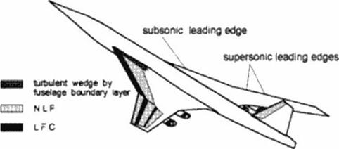
Efficient laminarisation of supersonic transpons requires a hybrid approach. Figure 108 shows a concept oriented on the different physical properties:

Figure 108 Possible Laminarisation Scheme

The inner wing has high sweep angle with subsonic leading edges (the leading edge stays within its own Mach cone). Therefore the leading edge is rounded with a radius which still inhibits usage of pure Natural Laminar Row (NLF) techniques, but requires Laminar Row – Control (LFC). NLF means that laminarisation is achieved solely by suited shaping which con­trols pressure gradient and • at the leading edge – 3D divergent flow. LFC uses artificial meas­ures to alter the boundary layer flow, e g boundary layer suction, to improve the boundary layer velocity profiles w ith respect to laminar disturbance damping.

The outer wing and the empennage probably have supersonic leading edges (the lead­ing edge is outside its own Mach cone). Those leading edges usually are sharp. Possibly NLF can be used behind sharp leading edges, at least as long as profile curvature remains very small. But local Reynolds numbers grow rapidly leading to transition. In addition, curvature intro­duces pressure gradients which – on swept wings – lead to pressure gradients normal to the flow direction: this provokes some destabilising boundary layer crossflow waves. Suction can pro­long the laminar flow region. Before reaching die hinge line of deflected rudders, the boundary – layer should become turbulent in order to avoid unfavourable shock/boundary layer interferen­ces with laminar separation.

As long as the fuselage boundary layer is turbulent, a turbulent wedge extends at the wing along the intersection with the fuselage. This is a significant part of the surface of SCT – wings which have large root chord length.

In a NASA-stud/ (377J Boeing has investigated the impact of laminarisation on super­sonic transports. Table I shows the improvements due to laminanzation for a 250 passenger transport, design Mach number 2.4 and optimistic – but at least comparable – design ranges of 5000 nm and 6500 nm. The additional weight for the suction system of about 4.5 tons and the thrust reduction by 0.2% arc ncgligeable when looking at the benefits:

• reduced fuel heating, essential at Mach 2.4 over long ranges

• important weight reductions

• significantly reduced fuel burned.

This was demonstrated in a first study neglecting some snow ball effects; further improvements after optimisation arc expected

Suction System

Benefits for

SQfiQnm

6QQQnm

weight

4.5 t

fuel heating

-25.0 %

thrust reduction

0.2%

MTOW

-8.5%

-12.5%

OEW

-6.0%

-10.0%

block fuel

-12.0%

-16.0%

MTOW iurt>.

350.01

530.01

MTOW: maximum takc-of! weight OEW operational empty weight

Table 1: Laminar Flow SCT-study (377)- Mach 2 4. 250 passengers

The 6500 nm turbulent aircraft could not be realized with the assumed weight limit of 500 tons. But according to our experience, probably the weight of an SCT must even stay below 400 tons for take-off noise limitations. Over 400 tons all designs seem to diverge; especially because the absolute noise limit is reached, whereas at lower weight noise limits arc related to take-off weight.

Future Supersonic Commercial Transports

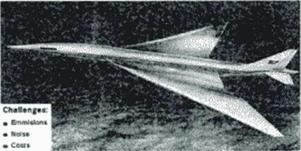
Realisation of a new Supersonic Commercial Transport (SCT) must meet challenging environ­mental and cost requirements (Figure 105). It can be certified only when meeting the future rules on emissions and noise, and if it will bring some profit to manufacturers and airlines. Drag is directly related to fuel burned, emissions and operating costs; but it influences also noise via air­craft size and weight. At the time being, the perspective for a new SCT improves; although emis­sion restrictions may question "if, whereas noise and costs ask "when" it becomes possible.

Figure 105 A New Supersonic Commercial Transport

An SCT makes sense only for long ranges of at least 2000 nm. The longer the dis­tances the more it becomes attractive for the passengers. At flight times of more than 4 to 6 hours most passengers feel uncomfortable and many see flight time as a waste of time, even tourists. But the SCT has to compete against future new subsonic aircraft (Figure 106) provid­ing more space and comfort for better accomodation of a long flight time. These aircraft will have low operating costs which cannot be met by an SCT. So the SCT has to compete with speed comfort and productivity against efficiency and space comfort.

Figure 106 Future Long Range Aircraft

To meet these challenges, the aircraft must be optimized mainly respecting the four different de­sign points:

• very efficient supersonic cruise at Mach 2 to 2.4.

• quiet take off and landing at steep flight path angles.

• high subsonic cruise capability (Mach 0.9) for flight over inhabitated areas, where super­sonic flight is not permitted.

• transonic acceleration at about Mach 1.1.

For all four points minimisation of aerodynamic drag is one of the challenges Drag contributions arc:

• wave drag

• vortex drag

• friction drag.

In this chapter emphasis is put on friction drag reduction by lanunarisation

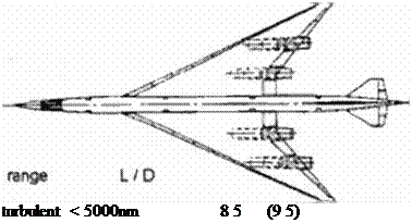
An SCT has a large wing area, about 3 times the size of comparable subsonic aircraft (Figure 107). It cruises at low angle of attack and low lift coefficient Cl due to the high lift dependent drag (consisting of wave drag and induced drag). Fnction drag contributes by about 35% to overall drag during supersonic cruise. It can significantly be reduced by lanunarisation. Present SCT-designs achieve a lift to drag ratio (L/Di of about 8 5 for a turbulent wing With partial laminarisation nearly 10 may be possible. The goal is at 9.5 for turbulent and 11 for lam­inar flow. The maximum range of a 250 – 300 passenger SCT in the year 2010 is expected with a turbulent wing at less than 5000 nm and w ith laminarisation at about 6000 nm. for a take off weight below 400 tons.

Подпись:large wng area

low

ca. 35% fnctxm drag

Design range at realization limit:

laminar < 6 000nm 10 (11)

Figure 107 SCT-Charateristics

LAMINAR FLOW FOR SUPERSONIC TRANSPORTS

J. MertCDS

Daimler-Benz Aerospace Airbus GmbH, Bremen, Germany

18.1 Introduction

Supersonic transports arc very drag sensitive. Technology to reduce drag by application of lam­inar flow, therefore, will be important; it is a prerequisite to achieve very long range capability. In earlier studies it was assumed that SCTs would only become possible by application of laminar flow |376|. But today, we request an SCT to be viable without application of laminar flow in or­der to maintain its competitiveness when laminar flow becomes available for subsonic and su­personic transports By reducing fuel burned, laminar flow drag reduction reduces size and weight of the aircraft, or increases range capability – whereas otherwise si/e and weight would grow towards infinity. Transition mechanisms from laminar to turbulent state of the boundary – layer flow (ALT, CPI. TS1) function as for transonic transports, but at more severe conditions; higher sweep angles, cooled surfaces, higher inode instabilities <HMl»must at least be taken into account, although they may not become important below Mach 3. Hitherto there is a worldwide lack of ground test facilities to investigate TSl at the expected cruise Mach numbers between 1.6 and 2.4; in Stuttgart. Germany one such facility – a Ludwicg tube – is still in the validation phase A quiet Ludwicg tunnel could be a favourable choice for Europe But it will require a new ap­proach in designing aircraft which includes improved theoretical predictions, usage of classical wind tunnels for turbulent flow and flight tests for validation.

. Technology Assessment

Evaluating the influence of new technologies on the aircraft design and get the benefits (or pen­alties) in the operating cost is a major part of the work in the future project office. Such studies were traditionally done by fixing all parameters and make a one dimensional analysis. But this approach docs not allow for second order effects which can compensate or enhance the influence of the parameter on the aircraft design. The MIDAS concept enables the project engineer to eval­uate the consequences of technology introduction fast and considering all aspects of the global model.

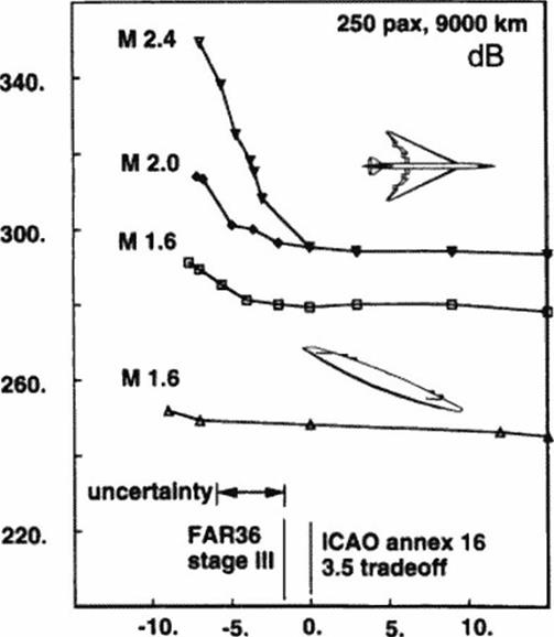
For the supersonic transport of the next generation an optimistic maximum noise sup­pression level of approximately 14 dB must be taken into account for reaching the goal of FAR stage 3. The weight increase and the thrust loss due to the noise suppressor arc incorporated in

the model as ( 10 )0S’AdBj ^ loss of thrust and 5** increase in nacelle weight per dB of sup­pression. Figure 104 shows the change of Aff. if the technical target of the year 2005 w ill not be

achieved or surpassed. The OFW shows a relatively neutral behavior, due to his flexibility to compensate surpressor nonperformance by reducing thrust requirements. For the SWB a short­fall of the target will he fatal especially for Mach numbers over 2.0.

Подпись: MTO (t)

Figure 104 Effect of noise regulations

In ref. (374) further examples of technology assessment studies with MIDAS are

given.

Acknowledgements

The author would like to thank all the people at Deutsche Airbus SCT-team who contributed to make this project especially our project manager Dctlcv Renners and Dirk von Reith in Ham­burg. Special thanks also to Prof. Kroo’s aircraft design group at Stanford University for their work on the Genic optimiration shell and to Prof. Yoda for her constructive editing.

17.5 Conclusion

In (his chapter we discussed a design strategy which given a mission finds the optimum aircraft design in the analysis parameter space. This parameter space is determined by the various disci­plinary groups. Based upon this input robust physically correct analysis modules were devel­oped. Improved non-linear optimization techniques were used to find the best design using these modules in this parameter space. This strategy reduced the number of design cycles and allowed us to evaluate more configurations. The ability to evaluate more configurations is essential for projects with high development cost that depend on the realization of aggressive technology tar­gets. In the case of the supersonic transport this ability allowed us:

• to investigate a wide range of solutions to find one which will be flexible enough to compete in an unknown market 30 years from now.

• to build scenarios to find out what happens w hen the design requirements will change or tech­nical targets cannot be reached

• to find out where wc have to invest work in detailed technology programs to get the best re­sults.

The present method was used to study the relative performance of symmetric wing

body (SWB) and oblique flying wing (OFW) and oblique wing body (OWB) supersonic trans­ports over a wide range of missions. The conclusions of this study where.

• Supersonic transports achieve their highest profit potential at Mach numbers between 1.6 and 2.0 and are able to compete with subsonic transports when adequate structural and noise re­duction technology is available.

• Noise regulations and runway loads may limit the size of symmetric wing body configura­tions with cruise speeds over Mach 2.0 to 350 tons. Only with very aggressive technology assumptions will such a transport be able to transport 250 passengers across the pacific.

• It is possible to reduce the total operating cost per seat of supersonic tranpsports by increasing the payload size up the maximum that is allowed by runw ay load and noise constraints. Larg­er payloads use the available volume more efficiently for a given passenger cabin standard.

• The best oblique flying wings arc large and long range. They are compatible to the current traffic infrastructure, and not dependent on very aggressive technology assumptions. In addi­tion. they produce less sonic boom and can comply with stage 4 noise regulations. [10]

Variation of Range, Mach number and Payload

Range

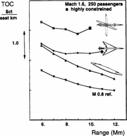
Figure 101 shows that this OFW’ is able to achieve ranges of up to 6500 nm (12000 km). Span­loading enables the OFW’ to improve both range and TOC Лк OFW’ has has a similar reduction of TOC with range as the subsonic reference. Лк tnp cost due aircraft ground handling, baggage handling, administration and landing fees arc only w eakly dependent on range. As a consequence the indirect operating costs (IOC) per available scat km reduce with range. This effect is not so clearly visible for the SWB’s. Beyond 6000 km range the direct operating cost per available scat increases fast. And at 9000 km it increases faster than the decrease of the IOC’s. Relative to the subsonic reference the SWB seems to be most attractive for the transatlantic range. Beyond 11000 km us maximum takeoff weight snowballs, even with our aggressive technology assump­tions. The OWB even has problems making it across the pacific.

Type

SWB

SWB

OFW

Cruise Speed

MO.8

MI.6

MI.6

Wing Area (m2)

304

625

1290

Rool. Tip t/c (%)

15/11

4.9/3.5

19/13

l. e. Sweep

29 deg

57 deg

70 deg

cabin 1 x w (m)

44 x 4.9

55 x 4.2

25 x 8.0

total 1 x w (m>

62×49

89×47

120 x 15

Weights;

DEM (t)

61

114

99

«„(к*)

139

266

238

Powcrplant

SLS Thrust (kN)

4×63

4x 196

4×210

BPR

5.1

0.7

0.8

e

50

44

32

c, ma. i

TT4 (K)

яка

1800

1800

1800

Operation

Initial Cruise

L/D

17.9

9.9

10.5

s. f.c.

0.61

0.94

096

h

11200 m

13300

14800

TOC ctJsrat. km

ref.

+ 16*

+ 10*

Environment:

Mean Д PiN over m2)

95

44

SL Noise (dB)

89

103

102

TO Noise (dB)

102

106

103

AP Noise (dB)

98

99

103

Table 5 Reference Aircraft (9000 km / 250 pax )


Figure 101 TOC as a function of range

Mach number

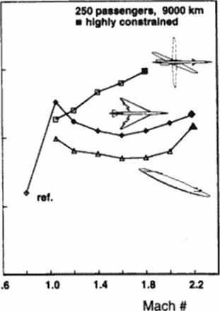
Figure 102 shows the influence of the increase in speed from Mach 0.8 to 2.0 on TOC for the SWB’s and the OFW’s. The dominant influence is the price of wave drag added to super­sonic configurations. At supersonic speeds the increased specific airframe complexity increases the purchase price and therefore the direct operating costs. Over a wide range of Mach numbers the SWB’s and the OFW’s have similar lift-to-drag ratios and similar specific fuel consump­tions. The structural weights arc completely different. Both concepts have their minimum TOC at Mach 1.6. Mach numbers in excess of 2.0 arc probably not possible due to thermal stability problems with conventional fuels for trips in excess of 3 hours. In addition we found that a number of these designs were limited by as many as a dozen constraints at the same lime This is caused by incompatibility of low-speed and high-speed flight. The OWB is worse than the SWB except at very low supersonic speeds As we discussed before, the OWB improves more than the SWB if wc consider a lower range. Our calculations therefore agree with the 1977 Boe­ing High-Transonic Speed study by Kulfan. Neumann ct al. (365) that stated that the OWB is slightly superior to the SWB at Mach 1.2 and a 5500 km range. Our calculations however, do not support the claims made by the 1991 GE study of Elliot. Hoskins and Miller {360] that this configuration is superior to the SWB at 9000 km and Mach 2.4. Al Mach 1.8 the lift-to-drag of this configuration is already dow n to 7.5 because of excessive wave drag. In addition the struc­ture is very poor because of the single pivot that has to transfer all the loads.

Figure 102 TOC M a function of Mach number

Payload

The overall trend that the TOC’s reduce with increased payload is caused by die reduc­tion of the DOC’s per passenger km. with payload Maintenance costs, fuel burn and deprecia­tion do not nse (exactly) proportionally to the number of passengers transported. This effect is even a bit stronger for the supersonic transports. The larger area-ruled supersonic transports have a better cabin volume efficiency then the smaller ones. However, only supersonic configu­rations that are not highly constrained benefit from an increase in payload with respect to the subsonic transports. Because of the poor volume efficiency of the OFW configurations, the standard payload of 250 passengers may not be large enough. For the OFW a payload of 400 passengers is better It is not possible at this time to design a 400 passenger SWB SCT configu­ration since such an aircraft w ould have an excessive M^. How ever this study does seem to jus­tify the approach of the American HSCT teams (NASA. Boeing. MDD) (357) to transport the most passengers for a given The M^^ is for all practical purposes limited to 350 tons. At

higher takeoff weights the critical sideline noise constraint is no longer relaxed to accommodate heavier aircraft. Figure 103 shows the effect of increased payload on the TOC of the OFW. If we compare the 250 and 400 passenger OFW’s we find that the maximum takeoff weight has increased 33% while the payload has increased 60%. A detailed explanation of the improved economy of the oblique flying wing transport over the symmetric wing body is published in ref. 1371].

Pax#