Category Principles of Helicopter Aerodynamics Second Edition

Airfoil Sections

The choice of airfoil sections for helicopter rotors requires special consideration because significant improvements in rotor performance can be realized with the optimal selection of airfoil shapes. This is of such fundamental importance to helicopter design that Chapter 7 is devoted to a basic understanding of the subject. Early helicopters used deriva­tives of NACA 0012 or NACA 230-series airfoils, which gave a reasonable compromise in overall performance. These can be considered as “first-generation” airfoil sections – see Fig. 6.17. Later, helicopters began to use a variety of airfoils sections that were optimized to match the aerodynamic requirements of each station along the blade. This is required

Подпись: N АСА 0012 Подпись: NACA 23010

First generation airfoil sections

Second generation airfoil sections

Airfoil Sections Airfoil Sections

‘High-speed" airfoil sections

Figure 6.17 Airfoil sections for helicopters have been specifically developed to meet the aerodynamic conditions actually encountered on the rotor.

because during each rotor revolution, the airfoil sections on helicopter rotors encounter a wide diversity of operating conditions. For example, for a representative blade station (say at 75% blade radius) the aerodynamic environment in which this section operates in hover and forward flight are different. On the advancing side of the rotor disk the blade sections may reach high subsonic speed and in high-speed forward flight they may penetrate into the transonic flow regime. This causes wave drag, and if the shock strengths become sufficiently severe, shock induced flow separation and stall may be produced.

On the retreating side of the disk, the blade tip sections operate at subsonic speeds, but at much higher angles of attack, eventually close to stall. Therefore, the blade sections must be thin enough to maximize the drag divergence Mach number, while simultaneously they must have some minimum thickness and incorporate some camber to give a relatively high C/max but still maintain low pitching moments throughout. No single airfoil profile will meet all these requirements and the airfoil(s) must be designed to reach a compromise between the requirements of all flight conditions, both at low and high airspeeds and also at high thrusts. Margins for maneuvering flight and turbulent air conditions must be factored in to the design to allow for sufficient performance. In general, the goal is to find airfoil sections that balance the advancing blade requirements (high drag divergence Mach number) with those of the retreating blade (high maximum lift at low Mach numbers), while maintaining a good overall lift-to-drag ratio throughout. This will help to maximize rotor efficiency throughout the flight envelope.

While rotor efficiency is often viewed simply as a hovering efficiency, forward flight efficiency (i. e., the effective lift-to-drag ratio of the rotor) is also important. But consider first the hovering efficiency. The airfoil requirements can be examined by rewriting the
figure of merit in another form to that shown previously. For a rotor with rectangular blades then

Подпись: C

Airfoil Sections Airfoil Sections Подпись: (6.14)

3/2

Airfoil Sections Airfoil Sections Подпись: (6.15)
Airfoil Sections

The mean lift coefficient of the rotor is Сц = 6(Cj/a) and it will be assumed that all the sections operate at the same Cd — Cd, an approximate but useful assumption. In terms of Ci and Cd the figure of merit becomes

Therefore, the figure of merit will be a maximum when all of the airfoils comprising the rotor blades operate at their best values of the ratio C^2/ Cd – see also Question 6.1. This result has been pointed out by many authors, including Gessow & Myers (1952), Prouty (1986), and Stepniewski & Keys (1984). While in practice not all the airfoils on the blade can operate at the same condition because of the varying Mach number and Reynolds number along the blade span, the forgoing result does show the need for good airfoil designs, in general, to obtain maximum hovering rotor efficiency.

This requirement is summarized in Fig. 6.18, where Eq. 6.15 has been rearranged to solve for cV2 ICa as a function of the induced cower factor к for several values of rotor FM. It is

——- I, – M. – x
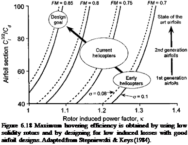
Подпись: Figure 6.18 Maximum hovering efficiency is obtained by using low solidity rotors and by designing for low induced losses with good airfoil designs. Adapted from Stepniewski & Keys (1984).

clear that to achieve a state-of-the-art rotor design the induced losses should be low (by means of appropriate blade twist) and the value of cf^2/Cd for the airfoils should be large (through appropriate airfoil design and blade solidity selection). It would seem that values of FM of 0.80 or higher are only possible with an extremely careful rotor design (using optimal

Airfoil Sections

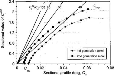
Figure 6.19 A form of 2-D drag polar for an airfoil showing that much higher values of

3/2

Cz /Cd are only possible through reductions in profile drag and increases in maximum lift coefficient.

blade twist, planform and tip shape) and also by using very advanced airfoils, perhaps with flow control devices to delay the onset of stall (see page 401). It is apparent, however, that after the airfoils reach high maximum values of Съ/ /Cd (say over 80), further gains in rotor figure of merit through airfoil design improvements alone are very much harder to come by.

A form of drag polar for two representative helicopter rotor airfoils is shown in Fig. 6.19. One airfoil represents a first generation airfoil section with relatively modest performance and the other is a second generation airfoil with lower profile drag and a better value of maximum С/, that is, Qmax. Also shown are lines of constant cf/2/Cd from 40 (a modest but realistic airfoil performance) to 100 (an excellent but perhaps unrealistic performance). It is clear from Fig. 6.19 that improvements in cf/2/Cd come about by decreasing profile drag to as low a value as possible while simultaneously increasing the maximum attainable lift coefficient to as high a value as possible. It is for this reason that helicopter design­ers have strived for many decades to develop high-lift/low-drag airfoils that retain these characteristics over a wide range of operational Mach numbers – see Chapter 7. It is also apparent from Fig. 6.19 that the maximum values of C^2/Cd are obtained over a good range of operating lift coefficients, usually in the range 0.7 < С/ < 1.2, and so the rotor can operate at its maximum efficiency over a fairly wide range of disk loadings. This is a clearly beneficial result, so the rotor does not become as much of a “point” design. Delay­ing the onset of stall and the drag rise at higher lift coefficients obviously helps to further maintain rotor efficiency. However, it is not realistic to expect on a practical rotor that the best values of C^2/Cd can be achieved simultaneously at all blade sections, nor that 2-D airfoil measurements are entirely representative of the aerodynamic behavior of the airfoils on the rotor. Yet the results in Fig. 6.18 indicate the general design goals.

Clearly, one way to help minimize profile power and maximize figure of merit in hover is to consider the use of an extremely low drag airfoil. As shown in Section 7.8, the airfoil profile drag consists of two parts, namely pressure drag and viscous (or shear stress) drag. The pressure drag can be minimized by using relatively thin airfoil sections, although the use of thin airfoils has some disadvantages as well, mainly because of the possibilities of

achieving fairly low maximum lift coefficients. The viscous drag component, represented approximately by the coefficient C^0, can be minimized by carefully controlling the airfoil pressure distribution and maximizing the chordwise extent of laminar flow, at least for a range of low to moderate lift coefficients. This is called a natural laminar flow (NLF) section. Unfortunately, there are other aspects of airfoil performance, such as the need for low pitching moments and high maximum lift, that usually preclude the use of special low drag or NLF airfoil sections on rotor blades. Also, environmental factors tend to produce insect accretion and blade erosion at the blade leading edge, which can cause premature boundary layer transition and reduce the run of laminar flow in any case. In some circumstances surface roughness can adversely alter other aspects of the airfoil characteristics such as by lowering C/max and/or changing the stall characteristics.

A powerful parameter affecting the profile power of the rotor is the airfoil thickness. Using 2-D airfoil measurements given by Abbott & von Doenhoff (1949), the zero-lift sectional drag coefficient for the NACA symmetric series can be approximated by the equation

Airfoil Sections(6.16)

where tjc is the thickness-to-chord ratio. The result is valid in the range 0.06 < t/с < 0.24. The effects of Mach number compound the behavior of the drag, but at moderate angles of attack below the drag divergence Mach number the effects of compressibility are small and are more sensitive to Reynolds number. Assume, for example, that a blade tapers in thickness from an airfoil with a 12% thickness-to-chord ratio at the root to an 8% ratio at the tip. Therefore, using Eq. 6.16 the drag coefficient can be written as

Подпись: (6.17)Q0(r) = 0.007 + 0.025(0.12 – 0.04r) = 0.01 – 0.001г.

The profile power coefficient can now be estimated using the blade element model where

Подпись: (0.01 - 0.00lr)r3dr.Airfoil Sections(6.18)

Evaluation of this expression gives a value of |<r(0.0092) compared to the value |cr(0.01) without the use of thickness variations (i. e., an 8% reduction in profile power). Typically, this would translate into an increase in figure of merit of between 1 and 2%. For a given rotor power or shaft torque, this would offer a 0.5-1.5% increase in overall vertical lifting capability (see also Question 6.8). This is significant; measurements by McVeigh & McHugh (1982) show a 5% gain in rotor figure of merit and a 25% gain in equivalent lift-to-drag ratio in forward flight through the use of advanced airfoil sections designed for lower profile drag and higher drag divergence Mach numbers.

The effects of Reynolds number variation of rotor profile power and figure of merit can also be estimated using this blade element approach. Based on the results shown in Section 7.3.2 it is apparent that the effects of Reynolds number on profile drag can be approximated from turbulent boundary layer theory by

Подпись: (6.19)

Airfoil Sections Подпись: (6.20)

С*, =0.1166 Re-0 2,

Airfoil Sections Подпись: (6.21)

which is based on an average of more than 40 different wind tunnel tests with the NACA 0012 airfoil, and this equation seems to offer a slightly better approximation in the higher Reynolds number regime (see Fig. 7.4). This suggests an increase in rotor profile power of about 15% when reducing the tip Reynolds number from 107 to 5 x 10⁵. Reducing further the Reynolds numbers to the values typical of micro air vehicles or MAVs (see Section 6.14 and Fig. 7.4) would suggest values of Cdo in the range of 0.03 with a corresponding fourfold increase in rotor profile power requirements. One approximation for low Re is to use the scaling

These high values of drag help explain the relatively poor hovering efficiency and low values of figure of merit of current rotating-wing MAVs (see Fig. 6.2 and Section 6.14) and the need for vast improvements in airfoil efficiency at low Reynolds numbers if these types of MAVs are to become more viable.

Consider now the effects of airfoil performance on the efficiency of the rotor in forward flight, which is explained by Stepniewski & Keys (1984). Consider the power requirements for the rotor in forward flight based on the results given previous in Chapter 5. For flight at some forward speed Voo (but high enough that Glauert’s approximation to the induced inflow is valid) and assuming the rotor thrust is equal to the weight of the helicopter, then the main rotor power required is the sum of its induced and profile losses, namely

P = ff^-+pA(QR?^( +4.65ц2), (6.22)

2pAVoo 8

Подпись: Р/Voo w Airfoil Sections Подпись: (6.23)
Airfoil Sections

where Co is assumed to represent the average profile drag coefficients of the airfoils on the blades. All of the other symbols have their usual meanings. We seek a result for the effective lift-to-drag ratio of the rotor, (L/D)r, in the forward flight condition in terms of airfoil properties. The rotor L/D ratio can be approximated by L/(P/ Voo) = W/(P/ Voo) – see Section 5.5.3. Therefore the ratio of D/L can be found using the standard form of the power equation to get

_6(CA_6( W

V or / o – pA(QR)2J ‘

Подпись: CL Подпись: (6.24)

Proceeding further it is convenient to write the rotor thrust in terms of a mean operating lift coefficient Cl, which working on the assumption that all blade sections operate at the same Q (as shown in Section 3.4.6) is given approximately by

Airfoil Sections Подпись: (6.25)
Airfoil Sections

With this result (D/L)r for the rotor can be written as

Подпись: C^best — 3 Airfoil Sections Подпись: (6.26)

Differentiating Eq. 6.25 with respect to Cl to find the value that will give the best (L/D)r gives
Airfoil Sections
drag coefficients of the airfoils comprising the rotor.

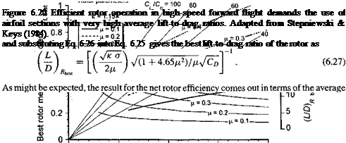
The results are summarized by the composite set of curves in Fig. 6.20 in terms of the mean operational lift coefficient required to reach the best L/D ratio (for a rotor of given solidity) at a given advance ratio versus the mean drag coefficient, Co, of the airfoil sections. The corresponding results for the best L/D ratio of the rotor are also shown. It is assumed that the induced factor к is known a priori. To understand this plot consider a given airfoil family with a known average value of Cd . The results show that for efficient flight at higher speeds the rotor must be operated at a relatively larger mean lift coefficients, which clearly requires airfoils with very good lift-to-drag ratios. The need for very high-speed flight (i. e., /л > 0.4) demands airfoil sections with extremely good average characteristics, that is, with 2-D sectional lift-to-drag ratios approaching 80. It will be apparent that for a helicopter of given weight operating at a given /x the value of Cl can only be reduced by increasing rotor solidity (Eq. 6.26), although this must always be at the expense of blade weight and some loss of hovering efficiency. These results, however, illustrate rather nicely some aspects of the design Irade-offs when develoning я trulv high-sneeH rntnr Rvstem. where it is clear that only so much performance can be gained from airfoil section developments and increases in rotor solidity. To further improve cruise efficiency at high speeds requires that the high average Cl/Cd of the blades be maintained by simultaneously delaying both the onset of advancing blade compressibility effects and retreating blade stall.

Blade Planform and Tip Shape

The tips of the blades play a very important role in the aerodynamic performance of the helicopter rotor. The blade tips encounter the highest dynamic pressure and highest Mach numbers and strong trailed tip vortices are produced there. A poorly designed blade tip can have serious implications on the rotor performance. Figure 6.13 shows some blade tip designs that have been used or proposed for helicopter rotors. There are several common designs, comprising those with taper, those with sweep, and those with a combination of sweep and taper. Some blade tips may also use anhedral, which, as shown by Balch (1984) and others, can improve the figure of merit of the rotor. A good analysis of the effects of anhedral is given by Desopper et al. (1986, 1988), Vuillet et al. (1989), and Tung & Lee (1994). An example of a state-of-the-art tip shape is that on the “advanced growth blade” designed by Sikorsky for the S-92 and later models of the UH-60. This unique tip incorporates all three geometric parameters, sweep, taper, and anhedral. Other special tip designs such as that used on the Westland/RAE BERP blade incorporate somewhat more radical variations in sweep, planform, and anhedral.

Подпись: і м rBlade Planform and Tip Shape
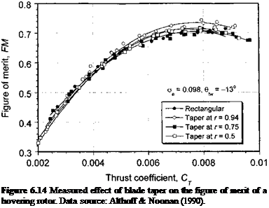
It is known from the analysis in Section 3.4 that blade planform can also have an important effect on the blade lift distribution and, therefore, on the rotor performance. Usually, small amounts of taper over the blade tip region can help to significantly improve the figure of merit (FM) in hover. This is confirmed in Fig. 6.14, which is taken from the subscale rotor experiments of Althoff & Noonan (1990). The benefits, however, seem to be lost for larger amounts of taper, most likely because of the higher profile drag coefficients associated with operation at small tip chord Reynolds numbers (see Fig 7.4). Nevertheless, the experimental results confirm the previous observations from the BEMT that a maximum figure of merit for the rotor can, in part, be obtained by using both a combination of blade twist and taper. The type and amount of taper and twist, however, needs to be factored into the overall rotor design and operational specifications. A 2:1 taper over the tip region seems about optimum for a helicopter blade.

Sweeping the leading edge of the blade reduces the Mach number normal to its leading edge, thus allowing the rotor to attain a higher advance ratio before compressibility effects manifest as an increase in sectional drag and an increase in net rotor power required. The use of sweep also affects tip vortex formation, its location after it has been trailed from the blade, and its overall structure — see, for example, the results of Rorke et al. (1972), Balcerak & Felker (1973), Spivey (1968), Spivey & Morehouse (1970), Carlin & Farrance (1990), Sigl & Smith (1990), Smith & Sigl (1995), and Martin & Leishman (2002). However, the problem of rotor tip vortex formation and the effects of tip shape on the vortex characteristics, such as the velocity profile and the diffusive characteristics, is still the subject of ongoing research; sys­tematic studies of the tip vortex characteristics generated by rotors with different tip shapes have not yet been accomplished. It is likely, however, that this is an area where research may lead to improved tip shapes and rotor blades optimized for lower induced drag.

Blade tips with a constant sweep angle and those with a progressively varying sweep angle have been used. Many modern helicopters (for example, the UH-60 Blackhawk and the AH-64 Apache) use some simple constant sweepback on the blade tip. The amount of sweep is usually kept low enough (< 20°) so that there are no inertial couplings introduced into the blade dynamics by an aft center of gravity or by aerodynamic couplings caused by a more rearward center of pressure. A constant sweep angle offers simplicity in design and construction, but may result in higher than desirable aerodynamic torsional couplings because of the rearward location of the local center of lift.

A blade tip with a progressive sweep angle can be designed on the basis of a simple 2-D blade element analysis. One criteria is to choose a sweep angle that is just sufficient to maintain a constant incident Mach number normal to the leading edge. The velocity normal to the leading edge, Un, is given by

Un = QR (r fi sin V0 cos Л, (6.10)

where A is the local sweep angle of the blade 1/4-chord axis (see inset in Fig. 6.15). The incident Mach number, Mr,^, is then

Подпись: (6.11)

Подпись: Figure 6.14 Measured effect of blade taper on the figure of merit of a hovering rotor. Data source: Althoff & Noonan (1990).

QR

Mr Ф = —— (r + /л sin V0 cos Л = Mqr (r + [i sin V0 COS A,

a

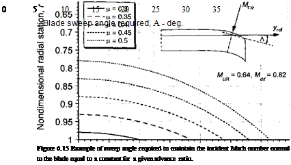
where a is the sonic velocity and M^r is the hover tip Mach number. Consider the design point as the advancing blade, that is, where л/г = 90°, and ignore any unsteady effects associated with the problem. If the local Mach number is to be maintained below the drag divergence Mach number, Mdd, then the sweep angle required to do this is given by

Blade Planform and Tip Shape(6.12)

For example, assume a typical hover tip Mach number of 0.64, and an airfoil with Mdd = 0.82. Then the sweep angle required to ensure that Mr ^ at each section remains just below Mdd is

Blade Planform and Tip Shape

Blade Planform and Tip Shape

(6.13)

The results are plotted in Fig. 6.15, where it will be seen that the 1/4-chord sweep angle is a smooth, almost parabolic, curve. With increasing advance ratio the amount of sweep required increases substantially and the sweep initiation point moves inboard on the blade. However, the amount of sweep that can actually be used or tolerated on a given helicopter blade clearly depends on structural dynamic issues as well, and such effects must be carefully examined. See also Questions 6.9 and 6.10.

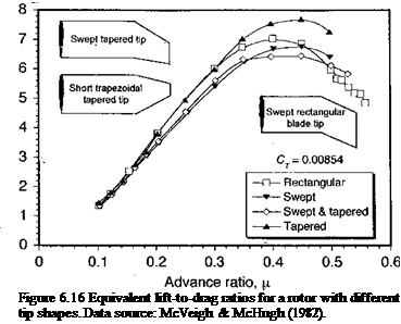
McVeigh & McHugh (1982) have conducted experiments with subscale rotors to study the effects of tip shape on overall rotor performance and cruise lift-to-drag ratio. It was shown that the combined use of improved airfoil sections and tapered tip shapes can help minimize profile power and significantly improve overall cruise efficiency of the rotor. The effects of tip shapes were examined for four rotors having rectangular, swept, swept-tapered, and tapered tips. All rotors were tested at the same lift, propulsive force and trim state, which provides a proper datum for performance comparisons. Figure 6.16 reproduces a summary of the results from McVeigh & McHugh (1982). The tapered tip was found to give about 10% higher equivalent L/D ratio compared to the rectangular blade, but interestingly enough the rectangular blade gave a better maximum cruise LjD ratio than either of the swept or swept tapered blades. This is because both the advancing and retreating blade characteristics of

Blade Planform and Tip Shape

the tip shape are important, and an integrated performance metric such as L/D ratio does not allow one to distinguish separately between these characteristics. While sweepback alone clearly has the advantage of delaying the onset of compressibility effects to higher advance ratios, the sweep may also promote early flow separation on the retreating blade at lower angles of attack. Therefore, there can be a performance penalty associated with a swept tip.

Yeager et al. (1987) and Singleton et al. (1990) have examined the performance of a tapered blade versus a blade with a simple swept tip and have found improvements in per­formance, with lower power requirements up to advance ratios of 0.4. Noonan et al. (1992) have examined the effects of blade taper alone on forward flight performance. Generally, small amounts of taper are desirable and help to improve rotor performance, at least up to advance ratios of 0.3. Larger amounts of taper yield much smaller improvements. Yeager et al. (1997) have tested a “BERP-like” (see Section 6.3.8) subscale rotor under similar controlled conditions and have compared the results to a rectangular blade with the same airfoil section. These and the other results confirm that a sophisticated swept tip design is by no means a panacea; each tip design must be assessed on the performance gains to be expected over the full operational envelope as well as within the overall requirements and constraints imposed by the rotor design process.

Blade Twist

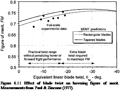
The proper use of blade twist (washout) can significantly improve the figure of merit of the rotor, a result found early on in helicopter development after the development of basic aerodynamic theory. This is reflected in Fig. 6.2 by the significant gain in the FM for the early Sikorsky R-4 helicopter by using redesigned blades with twist. Based on the combined blade element momentum theory (BEMT) discussed in Section 3.3, it has been shown that negative (nose down) twist can redistribute the lift over the blade and help reduce the induced power, but only to a point. Therefore, proper use of blade twist can significantly improve the figure of merit in hover. In Section 3.3.11 the effect of blade twist on the induced power factor has been shown based on analytical results. Paul & Zincone (1977) have shown the effects of blade twist on the maximum figure of merit deduced from full-scale rotor tests; these results are reproduced in Fig. 6.11. In general, the results confirm the theory in that the figure of merit of highly twisted rotors is nearly always better than

4-І* nf +ТТП nfa/4 пгічап nf fUa nnma /4 л olr 1 rv n/4ir» a

uiai iui iwidi^u lvstuia wn^u иртаии^ at tut aauit vxiojv iiiauiiig.

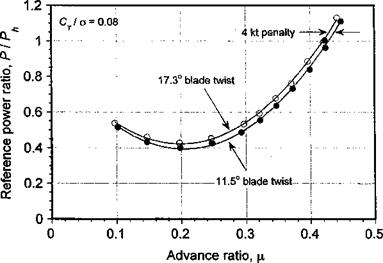
In forward flight, rotors with a high nose-down blade twist (say, greater than 15°) may suffer some performance loss. This is because of the reduced angles of attack can be produced on the tip of the advancing blade, resulting in a loss of rotor thrust and propulsive force. The problem has been explored by Keys et al. (1987). Results documenting the problem are shown in Fig. 6.12 in terms of power required (relative to hover power) versus advance ratio. Although not severe, some degradation in high-speed cruise performance is noted with the higher blade twist. Blades with very large twist rates, while offering performance benefits in hover, may suffer reduced or even negative lift production on the advancing blade tip and are obviously to be avoided. A survey of existing rotor designs

Подпись: Figure 6.11 Effect of blade twist on hovering figure of merit. Measurements from Paul & Zincone (1977).

shows that most helicopter blades incorporate a negative linear twist between 8° and 15°, with only a few exceptions. This twist range is a compromise between maximizing the FM of the rotor in hover at its design point (typically maximum hover gross weight), while simultaneously avoiding any detrimental effects on forward flight performance. Clearly, however, some gains in FM are possible if large values of blade twist can be tolerated. In the quest for high-speed forward flight capability of the helicopter, some manufacturers have used a nonlinear twist or double linear blade twist, where the effective twist rate is reduced or reversed near the blade tip. This helps give the helicopter better forward flight

Blade Twist

Figure 6.12 A loss of performance with highly twisted rotor blades may be expected in forward flight. Data source: Keys et al. (1987).

performance while retaining most of the hover performance and thus offers another good compromise for the rotor design.

Number of Blades

The selection of the number of blades for a rotor (for a given blade area or solidity) is usually based on dynamic rather than aerodynamic criteria, that is, it is based on the mini­mization of vibratory loads, which is easier for rotors that use a larger number of blades. Fewer blades, however, will usually reduce blade and hub weight, minimize hub drag, and may give better reliability and maintainability because of a lower parts count. Lighter weight helicopters usually have two blades, whereas heavier helicopters generally have four, five, seven or even eight blades. As shown in Section 3.2.4, aerodynamically the induced tip-loss effects are reduced by increasing the number of blades, but the effects on induced power are relatively small for the high aspect ratio blades typical of helicopter rotors.

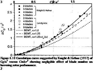
Knight & Hefner (1937) and Landgrebe (1972) have conducted systematic tests of blade number and solidity on rotor performance. Knight & Hefner tested subscale rotors with two, three, four, and five blades with no twist and at fairly low tip speeds. Landgrebe tested subscale rotors with two, four, six, and eight blades, linear twist, and at full-scale tip Mach numbers. All of the tests were done by adding blades to the rotor hub so the results cannot distinguish independently the effects of solidity from the number of blades. However, an analysis of these data suggest that hover performance is primarily affected by rotor solidity; the number of blades are secondary. Following Knight & Hefner (1937), the primary rotor behavior can be analyzed by the use of the blade element theory. From Section 3.2, the rotor-thrust coefficient is given by

Подпись:Number of Blades

Number of Blades

(6.6)

Also, ф{г) = X/r, and for a linearly twisted blade 0(r) = #75 + #tw(r — 0.75). Therefore

Number of Blades(6.7)

Number of Blades

when including tip losses alone through the factor B. Assuming uniform inflow, the corre­sponding power can be written as

Подпись: = XCT + Cp0 (6.8)

Number of Blades
Number of Blades

Incorporating other nonideal induced losses (other than tip loss) such that X = Ky/Cp/2 and dividing through by a3 gives

Number of Blades

Therefore, if the results from rotor experiments are plotted in the form of (Cp — Cp0)/a3 versus Ст/cr2, then this should remove the primary effect of solidity from the measure­ments. As shown by Figure 6.10, the results from both sets of measurements show good correlation with the result given by Eq. 6.9, confirming that the effect of blade number on rotor performance is indeed secondary. The modified results are based on the assumption that к — 1.25, В — 0.97 and a higher-order approximation for the profile power, both effects having been discussed previously in Section 3.3.9. Note that the latter assumption gives a small but significant improvement in the correlation at high values of thrust where

nonlinear drag effects begin to become important as the boundary layer thickens and the blade sections approach stall.

In subscale rotor experiments the effects of blade number can be masked by other effects, including those associated with the effects of Reynolds number and Mach number. The effects of Reynolds number can be particularly significant on small-scale rotors with small chords and tip Reynolds numbers that are often below 106 – see Section 7.9.1. Increasing the number of blades while maintaining the solidity of the rotor will decrease the blade chord and decrease the Reynolds numbers. Based on 2-D arguments this will tend to result in slightly higher values of the profile drag coefficient and, therefore, will give a small but finite reduction in the figure of merit.

A larger number of blades also leads to weaker tip vortices (for the same overall rotor thmst), thus potentially reducing the intensity of any airloads produced by blade-vortex interactions (all other factors being assumed equal). However, with more blades, the number of potential blade-vortex interactions over the disk will be increased (see Section 10.4.2). This can affect both the frequency and directivity of propagated noise, and the problem becomes far too complicated to make generalizations as to the expected trends. Furthermore, from the perspective of noise generation, a higher number of blades results in a smaller chord and lower “thickness” noise associated with each blade. However, even though the strengths of the tip vortices may be reduced by using a larger number of blades (at a constant thrust), the blades are closer azimuthally. Because the tip vortices are convected vertically only relatively slowly in hover and remain almost in the plane of the rotor, the following blades may more closely interact with the vortices from previous blades. Such a phenomenon has been encountered on hovering rotors with five or seven blades and can significantly affect predictions of induced power – see Clark & Leiper (1970).

Rotor Solidity

Rotor solidity, a, has been defined previously as the ratio of total blade area to the disk area (i. e., a = Nbc/тг R). Values of о for contemporary helicopters vary from about

0. 06 to 0.12. Smaller helicopters generally tend to have lower solidity rotors. It has been shown in Chapter 3 that the mean rotor lift coefficient is given in terms of the blade loading coefficient, Ст/сг, by Ci = 6{Ct/o). Typical values of CL for helicopters range from about 0.4 to 0.7.

Selecting the rotor solidity during the design process requires a careful consideration of blade stall limits, that is the mean lift coefficient where the rotor performance will be stall limited. Certification or acceptance requirements dictate the load-factors and bank angles that must be demonstrated without the rotor stalling. Normally civil helicopters require a minimum of 1.15 g or a 30° bank angle without evidence of stall at the maximum gross weight of the helicopter. Military requirements tend to be much more severe, however. Rotors that are designed for high forward flight speeds and/or high maneuverability re­quirements require a higher solidity for a given diameter and tip speed. Obviously, a rotor that uses airfoil sections with high maximum lift coefficients can be designed to have a lower solidity, all other factors being equal. Alternatively, the use of high-lift airfoil sec­tions permits a lower tip speed for the same solidity. Because rotor noise is considerably

Rotor Solidity

Figure 6.7 Measured figure of merit variation at different mean lift coefficients versus rotor solidity for a constant tip Mach number of 0.6. Data source: Department of the Army, Engineering Design Handbook (1974).

reduced when the rotor is operated at lower tip speeds, the development of high-lift air­foils that operate efficiently over the diverse range of conditions found within the rotor environment has always been an important design goal for the helicopter industry – see Section 7.9.

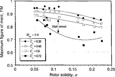
Figure 6.7 shows experimental results for the variation in figure of merit versus rotor solidity at different mean lift coefficients. These results simply reaffirm that one way to minimize profile power is to keep the rotor solidity as low as possible. However, this ap­proach must be done with caution because decreasing the solidity reduces the blade lifting area, increases the blade loading coefficients, and elevates the local and mean blade lift coefficients for a given rotor thrust. In other words, decreasing the rotor solidity decreases the stall margin, which is the margin between the average values of the operational lift coefficients and the maximum lift coefficient of rotor as a whole. For example, consider rotor operation at a nominal mean lift coefficient, Cl, of 0.6, as shown in Fig. 6.7. Then for a given value of solidity, operation of the rotor at a higher Cl results in a substantial degradation in rotor performance. This degradation is alleviated by increasing the solid­ity of the rotor, which helps reduce the local lift coefficients and improve the lift-to-drag ratios of the airfoil sections. Because the onset of stall sets the performance limits of a rotor, it is also very important to provide some additional stall margin in the rotor design to allow for normal maneuvers and gusts typical of turbulent air. The specified margin, which will vary for different helicopter designs, generally tends to set the lowest allow­able solidity to which the rotor can be designed. For example, a highly maneuverable combat helicopter will always require a larger stall margin than a civilian transport ma­chine. This is obtained, however, only with increased blade weight and higher overall rotor weight.

The onset of retreating blade stall in forward flight also limits the rotor performance. In forward flight, the rotor must provide both lifting and propulsive forces, the latter of which depends largely on the parasitic drag of the airframe but the rotor drag is also important. The stall inception boundary in forward flight can be most easily observed from strain-gauge

Rotor Solidity

Figure 6.8 Retreating blade stall inception in forward flight deduced from blade root torsion loads. Data source: McHugh (1978).

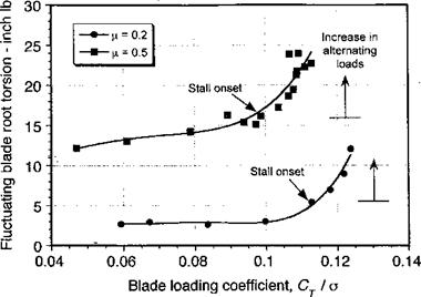
measurements of blade-pitch link and/or blade torsion loads. When stall occurs on the rotor, the mean (average) and alternating aerodynamic pitching moments increase dramatically. Representative measurements of the fluctuating component of the blade root torsion loads are shown in Fig. 6.8 as a function of Cj jo at two advance ratios of 0.2 and 0.5. At low advance ratios the blade root torsion loads are relatively low, but as Ct/o reaches about

0. 11, there is a more rapid increase as the rotor begins to show some evidence of stall. As the advance ratio increases, stall inception occurs at progressively lower values of Cj jo. At (Л = 0.5, the stall onset is more sudden and shows large increases in the fluctuating loads because of the onset of dynamic stall on the retreating blade. These fluctuating loads will manifest as high structural stresses in the blade and hub, and higher control forces, accompanied by significant increases of vibration levels. Stall will also cause longitudinal blade flapping, tilting the disk back (a fic blade motion) and decreasing propulsive force, therefore setting a natural barrier to further increases in forward speed. Higher control forces and the higher than normal vibration levels on the helicopter will serve as a warning to the pilot that the limits of the normal operational flight envelope of the rotor are being reached.

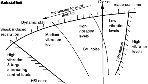
As already mentioned, propulsive force considerations also influence the selection of rotor solidity. In forward flight the function of the rotor is to provide a vertical lift force to overcome airframe weight as well as to provide a forward acting propulsive force. The overall envelope is summarized by Fig. 6.9, which is one type of representation of blade loading (or mean lift coefficient) versus propulsive force. The disk must be progressively tilted forward to provide this forward thrust (propulsion) component, and so stall onset will be obtained at progressively lower values of mean lift coefficient. Notice also that rotor noise issues become important in high-speed forward flight, particularly a form known as high-speed impulsive or HSI noise. Propulsive requirements can be reduced by minimizing the parasitic drag of the airframe or by thrust and/or lift compounding. While offering some advantages over a conventional helicopter, compound helicopter designs also suffer from many disadvantages as well – see Section 6.11.1.

Подпись: CH/oPropulsion Drag

Figure 6.9 Propulsive limits for a conventional helicopter. Adapted from Vuillet (1990) and other sources.

Tip Speed

Подпись: ШПодпись: Figure 6.4 General trends of main rotor disk loading versus helicopter gross weight.
A bmb глілг tir спррН Ьріпо tn maintain fbp 1пг*я1 vplnritipc япН Hpprpacp thf* япоїм

J. x 111^11 1.VW1 Jj^VVU llVlpU tv/ AifttULllttUll tiiv IV/VUt T V&V/VkVAWU VtllV* V*WA WMt/V Vl*V tUA^AW

of attack on the retreating blade, thereby delaying the onset of blade stall for a given blade area and advance ratio. A high tip speed also gives the rotor a high level of stored rotational kinetic energy for a given radius and helps reduce design weight. Because P = £2 Q, a high tip speed reduces the rotor torque required for a given power and allows a lighter gearbox and transmission design. However, there are two important factors that work against the use of a high tip speed: compressibility effects and noise. Compressibility effects manifest as increased rotor power requirements. If the drag divergence Mach number of the tip sections is exceeded, the sectional drag (and thus rotor power) increases dramatically – see Section 5.4.3. Therefore, reducing the tip speed permits a higher flight speed to be achieved

Tip Speed

Tip Speed

o:

a


Tip Speed

/ /// / / // Retreating blade /// // /1 stall І’т’* (airfoil / // / / /1 dependent) Ше^ХХ/


Below safe autorotational flight capability


Tip Speed

Tip Speed

Tip SpeedAdvance ratio, ц (or foward flight speed)

Figure 6.5 Aerodynamic, noise, and autorotative constraints imposed on the selection of rotor tip speed. Adapted from Prouty (1998) and other sources.

before compressibility effects become important. The use of a thinner airfoil at the blade tip and/or a swept tip shape can help significantly to delay the onset of compressibility effects to a higher advance ratio. Rotor noise increases rapidly with increasing tip Mach number. At low tip speeds, the noise resulting from the steady and harmonic loading on the blades is dominant. At higher tip speeds, the noise caused by blade thickness effects becomes an important contributor to the overall sound pressure, and the noise signature can become increasingly obtrusive.

Figure 6.5 shows what would be considered the range of acceptable tip speeds for con­ventional helicopters. The challenge for new rotor designs is to extend both the stall and compressibility limits to a higher forward flight speed. Yet, this is not easily achieved. The usual design constraints of maintaining good hover performance and acceptable autorota­tional characteristics (stored kinetic energy in the rotor system) severely limit the range of acceptable rotor tip speeds. However, the development of modem high-lift airfoil sections for rotors has permitted a reduction in rotor tip speed and, therefore, rotor noise levels, without compromising other aspects of the rotor performance. The use of thinner and/or “supercritical-like” airfoils and swept tips can also help alleviate compressibility effects – see Section 6.4.6. For many rotor designs, the autorotative kinetic energy limit may be an issue – see Section 5.6.3. Although this can be improved by adding rotor mass, the corre­sponding decrease in payload and the increase in blade and hub loads because of the higher centrifugal forces are usually unacceptable. In light of the foregoing, these issues tend to set the lowest possible allowable main rotor tip speed to about 680 ft/s (207 m/s) for a conventional helicopter.

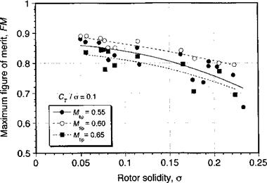
Systematic experimental measurements of rotor performance (thrust, power, figure of merit) at different operational tip speeds (or tip Mach numbers) and rotor solidities are relatively scarce. Figure 6.6 shows the effects of rotor tip Mach number on the figure of merit as a function of rotor solidity. While there is clearly scatter in the data, the results

Tip Speed

Figure 6.6 Measured figure of merit variation versus rotor solidity for different main rotor tip Mach numbers. Data source: Department of the Army, Engineering Design Handbook (1974).

confirm that operation at lower blade tip Mach numbers and lower rotor solidities is very desirable if hovering performance is to be maximized. At higher tip Mach numbers the rotor performance degrades because of the increasing compressibility losses. However, it must be recalled that rotor operation at low tip speeds will compromise forward flight performance because of the need for the retreating blade to operate at higher angles of attack and closer to the stall, all other factors being equal. In addition, the need to allow sufficient stall margin in the rotor design, especially for helicopters designed for high maneuverability and agility (see Section 5.9), requires the use of a higher main rotor tip speed.

Rotor Diameter

There are several conflicting factors that must be examined when determining the main rotor diameter. As shown previously in Chapters 2 and 5, both good hover performance and safe autorotational capabilities call for a large rotor diameter. The advantages of a larger rotor diameter are lower disk loadings, lower average induced velocities, and lower induced power requirements. It was shown in Section 2.12 that based on the modified momentum theory the operating thrust coefficient, Cj, to give the best power loading was

Подпись: for best PL,Rotor Diameter(6.1)

Rotor Diameter Подпись: W_ ~A
Rotor Diameter

which depends on airfoil section, rotor solidity and induced power factor. Using this result, the disk loading for minimum power loading will be

R = —=,/——- for a coaxial or dual rotor design,

V2V nDL 6

Подпись: and Подпись: R = Rotor Diameter Rotor Diameter

This equation determines the optimum radius of the rotor to maximize power loading at a given gross weight. Solving for the main rotor radius gives

imed that for design purposes each rotor of the dual rotor helicopter carries one half of the total weight of the aircraft. It has also been shown that

Подпись: (6.5)T FM

PL = — oc—— ,

P DL

which means for a given disk loading the rotor(s) should also be operated at the highest possible figure of merit. However, Fig. 2.16 has shown that the most efficient power loading (compared to the ideal value) is relatively insensitive to the operating state of the rotor, in that the power loading curve is fairly flat over the normal range of operational thrust coeffi­cients. Therefore, there is some latitude in selecting rotor radius, which may be constrained
because of factors other than pure aerodynamic considerations. For example, if the heli­copter is required to operate off loose terrain such as gravel or sand, the design may require the disk loading to be limited so that the downwash velocities remain low enough not to stir up any of the loose surface material. This usually means the use of a relatively high rotor diameter. A large diameter also means a larger inertia and stored rotational kinetic energy, which is essential for safe autorotational characteristics (see Section 5.6). Initial sizing studies of the main rotor must always consider autorotational capability, which will require some minimum rotor inertia if the helicopter is to meet the military acceptance criteria or civilian certification requirements. Both single and multiengine helicopters must demonstrate safe autorotative landing capability at maximum gross weights. Often the ini­tial rotor design is guided by previous rotor designs that are known to meet the autorotative specifications necessary for certification. An autorotative index of the form that was dis­cussed in Section 5.6.3 may be used as a means of quantifying the potential autorotative characteristics of a proposed new rotor design.

Usually a much smaller rotor diameter must ultimately be used than would be desired for best hovering efficiency (for a given blade area and tip speed) so as to meet overall helicopter size, weight, cost, gearbox torque limitations, speed, maneuverability requirements, and storage or transportation requirements for the helicopter. A smaller rotor will have a smaller and lighter hub and a lower overall parasitic drag, and so this will be more efficient for cruising flight. Smaller rotors also permit a more compact net helicopter design, which is useful for several operational reasons, including storage and transportation by sea and air. In addition, a smaller rotor diameter minimizes the static deflection or “droop” of the nonrotating blades. The static droop can increase quickly for larger rotor diameters and may cause problems when starting and stopping the rotor, especially in gusty wind conditions where the low centrifugal forces on the blades may lead to “blade sailing,” causing the rotor blades to flap and flex and perhaps impact the airframe. In most cases, the blade radius is usually kept to less than about 40 ft (12 m) otherwise the extra structure necessary to increase the blade stiffness will incur a significant weight penalty.

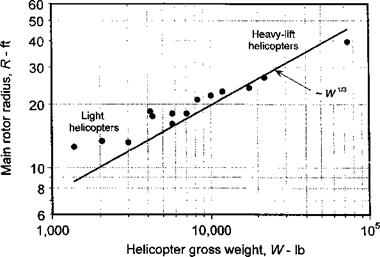
Figure 6.3 gives a summary of main rotor radius versus gross weight for a selection of helicopters (see appendix). Plotting the data on a logarithmic scale accentuates the

Rotor Diameter

Figure 6.3 General trends in main rotor size (radius) versus helicopter gross weight.

Подпись: Istrong correlation between the quantities. This plot shows that the helicopter weight grows much faster than the rotor size. The well-known “square-cube” scaling law gives a simple explanation for this behavior. For geometrically similar aircraft, the overall area of the aircraft increases with the square of a characteristic length, say /, and its volume by the cube of this length; so the weight of the aircraft, W, should also increase with the cube power of a characteristic length, that is, W а Iі or l oc W1/3. Therefore, for a helicopter R oc VF1/3, which indeed is the trend shown in Fig. 6.3.

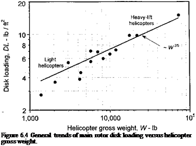
The corresponding trend of rotor disk loading versus gross weight is shown in Fig. 6.4. Remember that the disk loading must be kept as low as possible to maximize hovering performance, although with the larger and heavier helicopters this comes at some price. Because of the various other nonaerodynamic constraints posed in the design, such as the minimization of rotor weight and greater torque requirements, a large rotor diameter is not always practical. Generally, the manufacturer will try to find the smallest rotor diameter that will meet all of the specifications laid down for that helicopter. The square-cube law would suggest that T/A ос 1У1/3, but the results shown in Fig. 6.4 indicate a slightly more rapid increase such that T/A oc W2/5 because of the nonaerodynamic constraints. Therefore, the corresponding power loading will be proportional to W-1/5.

Design of the Main Rotor

Arguably, the main rotor is the single most important component of the helicopter. Good overviews of the design of modem rotor systems are given by JanakiRam et al. (2003) and Rauch & Quillien (2003). Proper design of the rotor is critical to meeting the performance specifications that have been laid down for the helicopter as a whole. The design of the tail rotor is similar to that of the main rotor, but because it has a different set of design constraints it will be discussed separately. There is still a great deal of activity in developing an improved understanding of helicopter rotor aerodynamics and in developing new and improved mathematical models that will more faithfully predict the flow physics and help design more aerodynamically efficient rotors of lighter weight. One should always bear in mind that small, systematic improvements in rotor efficiencies can potentially result in significant increases in the payload capability, maneuver margins, or the forward flight speeds of modem helicopters.

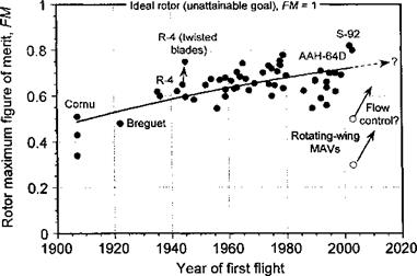
Rotor design efficiency is often measured by figure of merit (see Section 2.8), although its use as a comparative metric is restricted to rotors operated at the same equivalent disk loading. A historical record of measured main rotor figure of merit versus year of initial development is shown in Fig. 6.2, the data (in part) being compiled by Carlson (2002). It is clear that improvements in aerodynamic design have lead to state-of-the-art values of FM approaching 0.82. While substantial gains have been obtained over the years, the slow asymptotic nature of the faired curve suggests that further increases in the FM of helicopter rotors may require much more revolutionary developments in its aerodynamic performance. Potentially, this can be obtained through better integrated aerodynamic optimization of the rotor, such with the use of fully 3-D aerodynamic design techniques combined (perhaps) with the use of forms of active flow control (see page 401). It would seem that values of FM approaching 0.85 may be feasible, although much work remains before such goals are realizable. The current interest in hovering small remotely piloted helicopters and micro air vehicles (see Section 6.14) suggests that at this scale the rotors may have FM values that are close to half of those obtained with full-scale rotors, and clearly there is considerable opportunity for improvement here.

Design of the Main Rotor

Figure 6.2 Main rotor figure of merit versus year of development show sustained im­provements in aerodynamic efficiency, although future gains may be more elusive.

The conceptual and preliminary design of the main rotor must encompass the following key aerodynamic considerations:

1. General sizing: This will include a determination of rotor diameter, disk loading and rotor tip speed. There are several important trade-offs in performance and other characteristics with variations in all of these parameters.

2. Blade planform: This will include chord, solidity, number of blades, and blade twist. The optimal blade planform and twist distribution for hover may not be op­timum for high-speed forward flight. The consideration of other than a rectangular tip shape may be part of the preliminary design.

3. Airfoil section(s): These play an important role in meeting overall performance requirements. On most modem rotors, the use of different airfoils at various stations along the blade will be a likely design choice to maximize rotor performance.

Conceptual and Preliminary Design Processes

The methodology used in a conceptual or preliminary design study is an iterative process that begins with input specifications, such as the required payload and range of the helicopter. A series of performance and rotor sizing calculations based on these requirements are then undertaken using the elementary rotor theory described in previous chapters. The use of momentum theory in its various incarnations is very useful in this regard. Assessments of propulsive efficiency, lift-to-drag ratio, transmission power conversion efficiency, rotor tip speed, rotor figure of merit, and so on, are then performed. After these calculations are complete, a series of weight calculations are performed for the various components that make up the helicopter (rotor, blades, hub, airframe, engines, transmission, etc.). These weights are usually based on empirical equations, with the coefficients in these equations defined based on correlations to historical data. Next, these component weights are used to sum up the empty weight, the fuel weight for the mission is estimated, and the performance of the helicopter is recalculated. The updates are then substituted into the various weight equations and the process runs iteratively until convergence is achieved. Capital acquisition and direct operating costs are then evaluated.

Conceptual and Preliminary Design Processes Подпись: Sizina/Performance Calculations | Takeoff Weight Disk Loading Main Rotor Diameter Power Required (Hover & Cruise) Shaft Torques Tail Rotor Sizing (If Single Rotor) Specific Fuel Consumption WIng/Tail Sizing Conceptual and Preliminary Design Processes

The basic design methodology is depicted in Fig. 6.1. The logical sequence of this process allows trade studies to be performed and perhaps compared with other rotorcraft configurations. The intent is ultimately to select the best design that will meet the specified requirements at minimum cost. The conceptual and preliminary design process is then fol­lowed by a detailed design study at which the elements of the helicopter and its performance are examined in considerable detail. This is done using analysis, ground and wind tunnel testing, construction of a prototype, and finally flight testing. All of these steps involve considerable engineering time and large amounts of money. Flight testing is generally a protracted affair, often involving many months or even years of systematic testing before the helicopter is finally handed off to the customer.

Figure 6.1 Flowchart showing the conceptual design process for a generic rotorcraft.

Overall Design Requirements

Both the conceptual preliminary and detailed design processes comprise a highly interactive effort among aerodynamicists, structural dynamicists, aeroelasticians, material specialists, weight engineers, flight dynamicists, and other specialists. Prouty (1986) gives a good overview of the basic helicopter design process, particularly for military machines. The helicopter design must start with a clear set of specifications, which are defined based on the needs of a potential customer, or more so in the case of military machines, the needs to meet a specific mission requirement. Design technology for the civilian market is driven mostly by customers who emphasize reduced acquisition and operating costs, increased safety, reduced cabin noise and increased passenger comfort, and better overall mechanical reliability and maintainability. Because many of the helicopters in civilian use will operate from heliports and in populated areas, there is also an increasing emphasis on design for reduced external noise. The military have somewhat different requirements. They tend to demand much more in the way of flight performance, speed and maneuver capabilities, and damage tolerance, so the design of military helicopters is often much more difficult and expensive. Military planners also constantly emphasize the need of operational flexibility and adaptability and the need for long operational life with components that can be continuously upgraded. Vulnerability of the helicopter and the survivability of crew and passengers in a combat situation are also issues important to the military. Today, increasing emphasis is being placed on the dual use of military and civilian technology, which is simply the efficient integration of these traditionally separate design technologies. This has benefits for both the customer and the manufacturer.

The general design requirements for a new helicopter will include (not in any order of priority): 1. Hover capability, including both in and out of ground effect operations; 2. Maximum payload in different types of roles or missions; 3. Range and/or endurance un-

A «т. а.п.-.г І. х-ч-чт.-! flirtl-t* m.-L-L-L-l – TL, г – 1 тпігітпш nnn.-ij-li

uci uujLCicin uuiiuiuuiib, *+. v^i Л1ШЛШШШ icvci liigm ajjccu oiiu шалипшп uaan aj^cca,

5. Climb performance, both vertically and with forward speed; 6. “Hot and high” perfor­mance, icing, and other environmental effects; and 7. Maneuverability and agility (for mil­itary helicopters). One general objective for the manufacturer will be to design the smallest and lightest helicopter to minimum cost. A challenge in minimizing costs is to lower the design cycle time, and this is where the role of analysis and improved mathematical models becomes useful. However, the design must proceed on the basis of many constraints, which may limit the number of design choices. These constraints may include (not in any order of priority): 1. Maximum allowable main rotor disk loading; 2. Maximum allowable overall physical size of the helicopter; 3. One engine inoperative performance; 4. Autorotative ca­pability at maximum gross weight; 5. Maximum allowable noise (both civil and military);

6. Various civil certification or military acceptance requirements; 7. Crashworthiness and survivability requirements; 8. Maintenance issues; 9. Radar cross section and detectability (for military helicopters); and 10. Vulnerability (for military helicopters).

The various requirements for a new helicopter design will be initially specified by the Customer. ThcSC are then negotiated With the manufacturer аПи Written ІПІО a Sales СОП – tract. Often the “customer” will be the military forces, which will invite various competing manufacturers to respond to a “Request for Proposal” or RFP. Less often, the manufacturer will risk its own resources to develop a new design in anticipation of a production contract. In the design of the new helicopter, performance guarantees will be made to the customer based on various agreed metrics such as hover capability, payload, range and endurance, and cruise speed. In addition, the performance of the machine with one engine inoperative may be included in the guaranteed performance. Methods for determining compliance with the specified performance by means of predictions, analyses and flight testing will be detailed in the contract. Because any failure of the manufacturer to achieve the negotiated perfor­mance may result in substantial cost and other penalties, the manufacturer needs to have high levels of confidence that the performance guarantees can indeed be met.

The basic procedure that a manufacturer will follow in establishing a performance guar­antee is based on statistical confidence levels of results obtained from both mathematical models and flight tests. A good summary of some of the key flight testing activities con-

/^notarl rlnrirwt tVid логІїІїлоЬлп nf о тлНат Hi7in_otimna Viali і о niiran Ui; Ллігіаг

uuvitu umiug uiv vvxuiivuuvii vsjl «л. iiiwviu ivtjlu~V’ligiiiV’ nv/awpivi givwn uy v/vruwi /*

Confidence values can be assigned to predictions based on the established accuracy of a given mathematical model. Typically, most models will have been in use by the manufac­turer for some time and will be well-validated based on correlation with idealized laboratory experiments, ground and wind tunnel tests of sub – and full-scale rotor systems, as well as flight tests. This will allow the manufacturer to establish good statistical bounds on the confidence levels for the predictions. For example, methodologies validated with reference to a prototype or a similar helicopter will allow a high confidence level to be accessed. In contrast, a completely new helicopter with an advanced rotor design or new blade tip shape may have more uncertainties in the design, and confidence levels in any predictive

methodology will be lower. This, however, is where the benefits of fundamental research and development become useful, and significant payoffs can be realized by producing a much more advanced and competitive helicopter design.