Category The Aerodynamic Design of Aircraft

CONCLUSIONS AND OUTLOOK

We began this introduction to the aerodynamic design of aircraft with an overall assessment of the aeronautical scene, its technical prospects, and of its possible future social implications and motivations. This was a personal view, and some results were anticipated, which have only been des­cribed in more detail later on. We can now review very briefly the main conclusions to be drawn from the results obtained and how far they have taken us towards the aims set at the beginning.

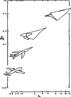
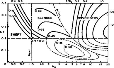
We have discussed design procedures in terms of various types of aircraft, and we distinguish between these solely on the basis of the different types of flow involved: the possible forms of aircraft were grouped together according to three types of flow which are, at this stage, known to be stable and eontvoVlable and, therefore, suitable for engineering applications. No excursion has been made in the discussions here into any other and less orderly flow regimes; nor was there any need for this: it is possible to construct a whole spectrum of major types of aircraft, which covers a network of global transport operations, on the basis of these flows alone. It is hoped that sufficiently convincing explanations have been given of why the types of aircraft can be classified according to their aerodynamic shape, as illustrated in Fig. 9.1, where speed and range are linked so that the flying time is much the same for all.

CONCLUSIONS AND OUTLOOK

Fig. 9.1 The spectrum of aircraft

Whereas the aerodynamic aspects alone allow us to define the types of aircraft and to describe the evolution of the aerodynamic shape, a more complete and unified treatment makes it necessary to consider also the non-aerodynamic aspects. A general method is applied for this purpose and this framework provides a good representation of the overriding trends in the aircraft characteristics, at least in those cases where it can be checked against the properties of actual aircraft. The main conclusion which can be drawn from these investigations is that the types of aircraft differ from one another not only in their aerodynamics but also in most other aspects. Thus different types of fuel go together with different types of aircraft and, in general, each of the latter requires a particular mode of propulsion and type of engine. Again, each is likely to be associated with the use of particular materials and methods of construction, and the modes of operation may also differ. As a consequence, the design procedures generally differ from one type to another, and entirely different types of layout are obtained. These profound and widespread differences between the types of aircraft require equally radical changes in the outlook and the attitude of research workers and designers. In this respect, some psychological difficulties must be overcome because the immense success of the traditional classical layout and method of construction has imbued us all with the notion that every aircraft should have a fuselage for providing the volume needed, separate wings for providing the lift, and separate engines for providing propulsion. We can see now that this concept applies only to classical and swept aircraft but not to slender wings and not to waveriders.

Classical and swept aircraft are designed according to Cayley’s concept and the means for providing volume, lift, propulsion, and controls are separate and largely independent of one another. The most significant feature of the results obtained for classical and swept aircraft is that the practical requirements are in complete accord with the Kutta-Joukowski type of flow and the assumptions of classical aerofoil theory. Sweep is primarily a means for reducing the flying time for a given range. Swept aircraft are eminently suited for flight over a network of short and medium ranges at high-subsonic and low-supersonic speeds. At higher supersonic speeds and longer ranges, the swept aircraft is likely to be superseded by the supersonic slender wing. The type of flow is characterised by vortex-sheet separations from the aero­dynamically sharp leading edges. A flight Mach number of around 2 is a good choice for a transatlantic range. An advantage is to be gained by going to larger sizes, when the means for providing volume and lift will be more and more integrated.

For the special purpose of flying large numbers of passengers or goods over very short ranges, the results suggest that the slender-wing type of aircraft offers a natural solution in the form of an allwing aerobus for subsonic speeds. The layout of this as yet hypothetical aircraft may be much more compact than the corresponding classical layout: its size may be smaller and its weight less, for a given payload. The relatively large passenger cabin performs a useful function as part of the lifting surface.

The waverider type of aircraft to fly at hypersonic speeds over very long ranges up to global distances is as yet entirely hypothetical. It is regarded as a genuine aircraft and not as an orbital transport or spacecraft. The wave – rider is the only type of aircraft among those discussed here where the type of flow changes during flight. At high speeds, the waverider is a fully – integrated non-slender propulsive lifting body with shockwaves contained between the sharp leading edges; at lower speeds, the flow is like that over

Conclusions and Outlook

a slender wing. The changes are expected to be gradual and smooth. The aero­dynamics are such that they allow the use of high-energy fuels with large volume requirements.

It should be noted that we have concentrated on the aerodynamics of what we consider to be the major types of aircraft and that we did not discuss the many existing and possible future derivatives of these. Thus jet-lift air­craft and rotorcraft for vertical take-off and landing have not been dis­cussed. Also, attention has been paid mainly to transport aircraft and not so much to special problems of military aircraft. But it is expected that many of the results discussed here can be read across to these special appli­cations, once they have been fully understood.

Another conclusion that should have become apparent is that the problems which are facing us grow in number and complexity (some discussion of these general trends may be found in AGARD AR-60 (1972)). This is partly a con­sequence of the fact that the requirements for performance, handling quali­ties, manoeuvrability, agility, and, above all, safety are much greater and more stringent than ever before. This is as it should be in a technology which is alive. In view of the very large funds which every worthwhile aero­space project demands, it becomes also increasingly important to ensure that the design aims will be achieved. Consequently, much more information, and much more accurate information, must now be provided before and during every stage in the design of an aircraft to give sufficient confidence for a suc­cessful outcome. Also, the lead time needed for results to be obtained and applied successfully is getting longer and longer. For the same reasons, the penalties for failing to meet the more exacting requirements and specifica­tions are now much higher, and design deficiencies which are discovered late in flight tests can seldom be remedied because of the cost and delays involved.

It is fortunate that the tools required to carry out this work, such as wind – tunnels and computers, have also become much more efficient and powerful and can be expected to continue to be improved. Looking back at the many prob­lems we have discussed, we become acutely aware of the need to use every tool at our disposal to the full so as to obtain the information required. How­ever, as scientists we wish to understand things, and as engineers we wish to alter things and make new ones. In both these undertakings, the acquisi­tion of data needs to be accompanied by the growth of conceptual frameworks, which can account for the data we already have and show us where more are needed. Above all, it is such conceptual frameworks which enable us to formulate intelligent ways of modifying and controlling our part of human endeavours. Ideas and concepts come out of the mind, not out of computers or windtwmels. If there is one overriding purpose throughout these notes above all others, it is to demonstrate the continued need for conceptual frameworks and for understanding the physics of airflows in any work on aerodynamic design.

It is also hoped that the reader will have come to the conclusion that aero­dynamic design is very much alive and that it would be a grave mistake to believe that we have already almost reached the ‘ultimate’. We have by no means reached the aims we can rightly set ourselves. It should have been made clear that major advances are still to come. In a very large number of instances, we have come to a point where we had to state that research had not been completed and had not been brought to any engineering application. Many new ideas and concepts have been described, which have never been taken up. There are probably more open questions than answers in these pages. The existence of so many open and loose ends may be interpreted in part as an indication that we suffer from the effects of vagaries of fashion and of rambling and capricious research policies and personal interests. These notes should prove convincingly that more steadiness and consistency in aero­dynamic research would be beneficial to advances in our knowledge and its application in aircraft design (see also J Seddon (1973)).

Altogether, we can look forward to the most promising technical developments in aviation, and in aerodynamic design in particular, with considerable improvements in existing types of aircraft to be achieved and major new types to be developed. A whole spectrum of aircraft appears before us, with a global network of routes where distances are measured in terms of hours.

This can have beneficial repercussions on the way we want to live, and avia­tion can play a vital part in the task of making man more in control of, and in harmony with, his environment. Never before have the technical and social prospects in aviation been so varied and promising. There is a very long way to go.

Propulsive lifting bodies

It is fairly clear by now what the properties should be of the combined flowfield generated by volume, lift, and propulsion: the compressions caused by volume and lift should be used in the first stage of the flow cycle with heat addition; the expansion stage of the flow cycle should be accomplished without introducing further shockwaves which cannot be utilised also for the provision of volume and lift; and all this should be achieved within a large number of constraints and extra conditions, such as heating, which include not only requirements for overall values for volume, lift, and thrust minus drag, but also details concerning their distribution over the body. However useful such a fully-integrated propulsive lifting body may be, the close integration of so many design parameters makes it difficult to establish a general and comprehensive design theory; an ‘aero­foil theory’ as for the other types of aircraft does not yet exist for wave – rider aircraft. All we can do here is to demonstrate some general design principles by means of specific examples.

At first sight, there seems to be a fundamental contradiction in this integra­tion: we have seen that aerodynamically efficient lifting bodies generate rather weak shockwaves, whereas flow cycles with heat addition are tradition­ally considered to need strong compressions, which can readily be generated in high-speed flight and are one of its attractions. We shall see later that this apparent contradiction can, in fact, be resolved.

With propulsion in mind, we may want to give the body a blunt nose with a strong shock and add heat there. H F Lehr (1972) has demonstrated that such a flow is physically possible and that steady Chapman-Jouguet detonations can be generated in a hydrogen-air mixture at Mach numbers around 5, as long as the velocity of the body is not below detonation velocity, when pulsating detonations occur. (He also demonstrated the existence of steady deflagra­tion fronts attached to the nose of a conical body.) However no thrust force was produced; instead, the drag was increased by heat addition at the nose of a blunt body. This result is only to be expected. It has been confirmed by a calculation of the simple flow of a combustible fuel-air mixture past a twodimensional double-wedge section at a Mach number of 5. A detonation wave, operating at the Chapman-Jouguet point, is assumed to be attached to the leading edge. The thermal efficiency of the flow cycle is quite good, at nth ~ 0.29 . But the drag is doubled, from Cq « 0.05 to 0.10, because of the large increase in pressure over the forward-facing surfaces due to heat addition. Thus nose burning does not appear to be suitable for practical purposes, although there may be exceptions: if the body is very blunt and has a very high drag, then this drag may be reduced by nose burning, just as nose blowing may do (see P J Finley (1966)). This has been shown theoretically by W Schneider (1968) and experimentally by F Maurer & W Brunge (1968). Here, we look for other ways of adding heat to the flow past a body which itself has a low drag.

A profitable line to follow is the addition of heat in a region of the flow – field where the body alone has an expansion, with the aim of eliminating it.

If we think of a lifting body like a caret wing but with the afterbody modi­fied to sweep upwards to a sharp trailing edge, then a good place for burning is on the lower surface of the afterbody, where some compression has already taken place upstream of it. The heat addition itself may again be thought of as either a detonation wave, assuming premixing of fuel and air is feasible, or as a diffusion flame. The suitability of afterbody burning was first recognised by К Oswatitsch (1959) and its physical existence has been demon­strated by experimental results such as those reported by G L Dugger (1959). Base burning, which has already been discussed, may be regarded as a special extreme case of afterbody burning.

We may again consider a simple flow of this kind, that of a combustible fuel – air mixture past a twodimensional double-wedge section, but now with a detona­tion wave, operating at the Chapman-Jouguet point, assumed to be fixed at the ridge line, with a strength and inclination which turns the flow behind the bow shock back along the afterbody, as sketched in Fig. 8.33. We take the

Propulsive lifting bodies

Fig. 8.33 Wedge flows at Mg = 5 without and with afterbody burning assuming onedimensional detonation characteristics

values behind the detonation wave as for a onedimensional flow, although we know that the characteristic direction in the flow immediately behind the wave lies along the wave so that the unknown, and neglected, wave beyond the intersection between bow shock and detonation wave will influence the flow over the whole afterbody. The results in Fig. 8.33 show that the initial expansion would be completely eliminated and the pressure enormously increased over the afterbody, in this simple approximation. The body would experience a large negative drag and the thermal efficiency would be nth “ 0.40 and the propulsive efficiency Лр =0.38 .

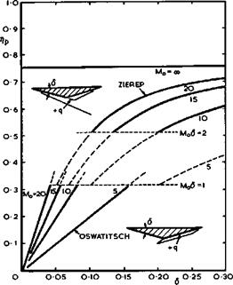
Other instructive examples of flows with external heat addition, which demon­strate effects of the mainstream Mach number, have been given by К Oswatitsch (1959) and J Zierep (1966). Both consider wedge-type twodimensional bodies with a flat top along the mainstream, with heat addition in some form over the lower surface of the afterbody, as sketched in Fig. 8.34. Oswatitsch

Propulsive lifting bodiesLIVE GRAPH

Click here to view

Подпись: Fig. 8.34Approximate propulsive efficiencies for afterbody burning

considers the case where heat, q, is added over an area adjacent to the rear of the body and assumes that both the wedge angle 6 and q are small and that the equations of motion may be linearised. The change in pressure caused by the heat input can then be determined and from it the propulsive efficiency. A simple analytic expression is obtained:

Zierep considers the case where heat is added along the first right-hand characteristic line, which passes through the shoulder of the body, up to a point from where the left-hand characteristic line just passes through the trailing edge (a further extension would not affect the pressure over the body and heat would be wasted). Zierep considers a non-linear hypersonic approximation and assumes that 6 <( 1 and (Mq6 )2 > 1 . Again, an analytic expression for the propulsive efficiency can be derived

Подпись: (8.30)

ГИи

b +

The results in Fig. 8.34 show that the propulsive efficiency increases con­siderably with increasing Mach number (the same trend as in Fig. 3.16) and with increasing wedge angle (i. e. with increasing pressure at combustion).

Propulsive lifting bodies Подпись: Г 0.76 o.43 Подпись: for у = 1.4 for Y = 1-1 Подпись: (8.31)
Propulsive lifting bodies

The latter implies, of course, that the drag over the forebody also increases. Thus a complete answer indicating the overall aerodynamic efficiency can only be obtained from a consideration of the whole flowfield or from the pressure distribution over the whole surface, not from the propulsive efficiency alone. We also see from Fig. 8.34 and equation (8.30) that the propulsive efficiency is bounded and cannot exceed the value

in this particular flow. This reminds us of the fact that the overall heat input in onedimensional flows is also bounded, equation (8.26). The full implications of this fundamental physical limitation in practical designs is not yet clear.

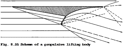
Подпись: Fig. 8.35 Scheme of a propulsive lifting body

We can now establish some of the general features which a propulsive lifting body with external heat addition will have. A possible simplified scheme is shown in Fig. 8.35. This may be thought of as a section of a twodimensional body or, alternatively, as the centre section of a caret-like threedimensional body derived from it, because the design principles discussed in section 8.2 still apply. It is assumed that it is not worthwhile to generate lift on the upper surface, and so all the important events are confined to the lower surface. One shockwave over the forebody provides lift, as on a caret wing, and also the pressure rise needed for adding heat, assumed to take place in a

suitably inclined plane. Downstream of that, the flow expands in a fhalf – openr nozzle and the shape of the lower surface of the afterbody will, in general, be curved. If freestream pressure is not yet reached at the trail­ing edge, which is assumed to be sharp, then at least one upper shockwave and a lower expansion fan will emerge from there. Another expansion fan will start at the lower end of the heating zone to adjust the pressure and flow direction to that behind the oblique shockwave which also starts at that point, as does a shear layer which divides the heated stream from the main­stream air. It is not likely that effects of viscosity will change this flow pattern in its essentials, although there may be a significant upstream influ­ence of the trailing-edge shock. It is clear that a body as in Fig. 8.35 will provide volume and generate lift and that the pressure drag may have a suffi­ciently high negative value to overcome the viscous drag. We can also read­ily think of variants of this general scheme, which may be more practical or more efficient. For example, it may be more efficient to achieve a required compression through several shocks rather than a single shockwave.

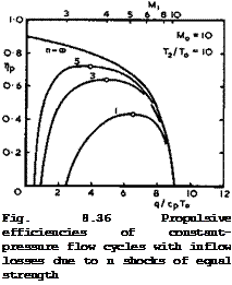
To get some idea of how much difference the shock system makes, we follow L H Townend (1966) and assume the inflow compression to be caused by a number, n, of oblique shocks. These are chosen to be of equal strength because equal-strength shocks give maximum pressure recovery for given n ; n ■ « then describes the isentropic compression. We assume that heat is added at constant pressure. All the properties of the flow cycle can then be deter­mined in closed form, as for the constant-pressure cycle in section 3.6, but now as they depend on the parameter n (for details see the original paper or section 6 of D KUchemann & J Weber (1968)). We reproduce in Fig. 8.36 some results for the propulsive efficiencies for fixed values of the main­stream Mach number and of the temperature ratio, T2/TQ, at the end of com­bustion. This temperature ratio has been limited to indicate that real-gas effects are meant to be avoided. Пр is seen to have a maximum value which depends on the value of n. This decreases considerably as the number of shocks is reduced. (The values for n = « in Fig. 6.35 correspond to the curves in Fig. 3.16). That there is such a maximum follows from the facts that a certain heat input is needed to overcome the inflow losses before a thrust is obtained, and that the heat input itself is limited. Thus inflow losses tend to bring us away from the extremely lean fuel-air-mixtures desirable in an ideal flow cycle.

Подпись: Fig. 8.36 Propulsive efficiencies of constant-pressure flow cycles with inflow losses due to n shocks of equal strength LIVE GRAPH

Click here to view

The shock losses in the inflow manifest themselves as both thrust losses and increases in specific fuel consumption. For a discussion of how these can be determined, we refer to section 9-3 of D KUchemann & J Weber (1953). Here, we illustrate this important fact by a numerical example by comparing values obtained for n = 3 with those for an isentropic inflow (suffix i), for Mq = 10 and a constant cross-sectional area at the beginning of combustion.

The local Mach number there is then Mj = 4 and q/CpTg = 5 . The propul­sive efficiency has fallen to Пр/Лрі = 0.84 . The pressure at the beginning

of combustion has fallen from рц/рд = 280 to P]/Pq = Ю0 . This is still

a very large value compared with those of turbo-jet engines operating at lower speeds; it shows the potential advantages of supersonic combustion.

The relative increase in specific fuel consumption due to inflow losses is 19% and the relative thrust loss is 71%. That the relative thrust loss is so much greater than the increase in specific fuel consumption is partly a con­sequence of the assumption that the front end of the combustion region has always the same size (i. e. Aj = A|. Inflow losses then reduce not only the pressure at which heat is added but also the mass flow through the com­bustion region. We conclude that we must not only aim at keeping the inflow losses small but also adjust the size of the ‘engine’ with a view to reducing the thrust losses, which in turn must be balanced against possible drag and weight increases and changes in lift and volume. This design process cannot be carried out without considering the propulsive lifting body as a whole.

Only a beginning has been made to clarify design aims and methods for com­plete propulsive lifting bodies, and we refer to the discussion of some simple cases in section 4.5 of D KUchemann (1965) and section 6.4 of D KUchemann &

J Weber (1968). An important aspect of the design of complete aircraft is the possibility of deflecting the thrust vector downwards. This has been investigated by J Pike (1971), who concluded that an efficient hypersonic cruising aircraft will have a significant fraction of its weight carried by the deflected jet generated by the heat addition. He derived a relation for the inclination of the propulsive jet, for certain optimum conditions. A considerable advance towards our aim was made in a series of papers by E G Broadbent (1969), (1971), and (1973). He developed an exact numerical method for calculating invisaid heated flows in twodimensions, which is practical and very fast on a computer. The method may be regarded as an essential first step which opens the way to various extensions: to the design of threedimensional propulsive lifting bodies; to make an allowance for the mass of the fuel, which may add significantly to the thrust; to include the effects of viscosity; and to take some account of the fuel-air mixing and of the chemistry of combustion. All this still remains to be done.

Broadbent uses an inverse method for solving the equations of motion. This approach is unfamiliar but has proved very successful. It is to prescribe the streamline pattern and then to calculate the distribution of heat sources needed to make the streamline pattern real. The resulting pair of equations in flow speed and pressure are linear hyperbolic equations with real character­istics along the streamlines and their orthogonal trajectories. The success of the method rests on this important property. It implies that numerical results can be obtained by marching along these characteristics from known conditions. This is done by putting a grid over the region of heating, with gridlines following streamlines and normals. Conditions are assumed known along the upstream normal and, in addition, one of the variables along one of the streamlines must be prescribed.. This, in fact, is just what we want to do in designing a body, because it enables us to choose the pressure distri­bution along part of the wall. The procedure is that the equations are first solved throughout the grid for pressure and flow speed and then the density distribution over the whole region is calculated from continuity. This, together with the pressure distribution, determines the state of the gas throughout the region, whence follows the enthalpy and hence the heat supply required. Most important, we obtain a complete flowfield and, by integration, the lift and thrust and drag forces as well as the volume capacity of the body. The procedure can readily be repeated and adaptations made, if the results do not seem to be satisfactory, for instance, if it turns out that negative heat sources are required or if the thrust is not large enough. The method is, therefore, especially suitable for the early project stage of an aircraft design and allows comparisons to be made between the performance characteristics of a wide range of these intricate and complex shapes.

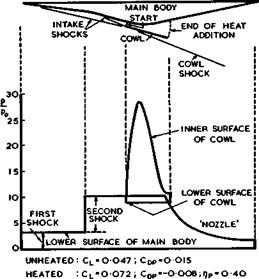
An example of Broadbent’s calculations is shown in Fig. 8.37. The main body

M0=7S

Propulsive lifting bodies

Fig. 8.37 Propulsive lifting body with heat addition within a duct. After Broadbent (1971)

is again flat on top and along the mainstream at Mq ** 7.5 . It has a cross­section roughly like a double wedge. The forebody is shaped to produce two shockwaves which would be followed by an expansion over the afterbody in the absence of heat addition. The body would then experience a small lift and a large drag. In this example, a solid cowl is added to the bodies, which begins at the point where the two ‘intake shocks’ intersect, and heat is added inside the duct so formed between the cowl and the body. This cowl was introduced by Broadbent because he found that purely external heat addition generally had a poor propulsive efficiency. Also, the mean pressure over the forward-facing surfaces was usually greater than that over the rearward-facing surfaces, and the net pressure drag was found to be positive, even though the heat addition greatly reduced it. Now, the pressure distributions in Fig.

8.37 indicate how the expansion is completely eliminated by specifying the pressure over the lower surface of the main body to remain constant at the

value behind the second intake shock. The pressure falls in the half-open nozzle downstream of the duct, but it stays positive. A large force is seen to act on the cowl: this contributes to the thrust force, at the expense of

some negative lift. However, the overall lift is considerably increased by the heat addition and the coefficient of pressure drag, Сдо , is now negative at a value which should be ample to overcome friction forces in steady flight, and which might allow some acceleration of the vehicle. But since the devel­opment of the boundary layer has not yet been investigated, and since no experiments on this general scheme have been carried out, it is not clear whether the flow can be realised in practice. In particular, it should be checked whether the boundary layer on the main body and that on the inside of the cowl will stand the pressure rises through the second intake shock and that behind the cowl lip.

The propulsive efficiency rip = 0.41 is quite good; it is somewhat below but not far short of that of constant-pressure cycles with intake shock losses discussed in connection with Fig. 8.36. But then this particular example does not in any way present the best that can be achieved. Broadbent has calcu­lated many more cases which give some clear indications of desirable aims and how these may be achieved. For instance, one way of improving the lift-to – drag ratio and the propulsive efficiency beyond those of the body with the straight cowl in Fig. 8.37. retaining the same two-shock intake, is to curve the cowl towards the body in such a way as to provide an expansion behind the cowl shook. One such section has given the following excellent set of values: – 0.084, Сцр “ -0.031, and rip = 0.66 at a maximum temperature of about 3000 K, at Mq – 7.5 . Another way of achieving improvements is to incorpor­ate a third shockwave, attached to the lip of the cowl. Whereas the first two wedges deflect the flow downwards, the third cowl shock deflects the flow upwards. This leaves the cowl set at a relatively small angle to the main­stream, and the net thrust may be improved at the cost of some loss in lift, because of the heavy download on the cowl. The propulsive efficiency is then generally between 0.6 and 0.7. There is obviously no limit to the number of variations that could be made, and it would seem advisable to bring in some practical constraints in further steps to be taken.

Very little work has as yet been done on stability and control problems of hypersonic flight and on the flight dynamics of the integrated waverider aircraft we have in mind. Some problems arising when control surfaces are deflected have been mentioned in section 8.4. Some stability and control problems have been discussed by R Ceresuela (1971) (see also F L Roe et al.

(1971) ). It may also be possible to read across from the many results obtained for the present generation of space shuttle orbiters.

It seems also worthwhile to explore the possibilities of using the propulsion system for control purposes. Thrust deflection, which has already been men­tioned, is one of these. But we have also seen how sensitive lift and drag are to the shape of the cowl for the heating duct and, of course, to the actual amount of heat added. These characteristics may also be exploited to control the moments of waverider vehicles. But no work is known to have been done on these important and promising prospects.

There is one further aspect of hypersonic flight, which may introduce new problems of stability and control. Waverider aircraft will most probably be designed to fly on great circles, but should the need arise, for example, to choose an alternate landing site in mid-cruise or to perform any other manoeuvre, then the aircraft must turn on a minor-circle path into a new great-circle trajectory. The longitudinal dynamics of a self-propelled lift­ing vehicle flying on a great circle have been investigated by В Etkin (1961) and non-linear dynamics have been studied by N H Vinh & A J Dobrzelecki

(1969) . T R F Nonweiler (1959) has considered in qualitative terms lateral stability problems near orbital speed. But flight on a minor circle requires a directed aerodynamic force, the direction being a function of speed and of radius of turn. This leads to new characteristic coupled modes, involving the movement of the centre of mass relative to the equilibrium flight tra­jectory which are not present in conventional flight. These problems have been dealt with in an extensive review by A M Drummond (1972) of the steady and perturbed motions of a rigid aircraft flying on a minor circle at con­stant altitude above a spherical non-rotating earth. Performance considera­tions and technological boundaries define an operating regime within which flight is possible, the main limitation being the available thrust. Stability considerations lead to the conclusion that some characteristic oscillation about the steady-flight condition may be poorly damped. Also, some minor instabilities were found. But altogether, Drummond’s investigations show that there exists a sufficiently large operating region which is left open for all envisaged uses of transport aircraft, even under these severe flight conditions at very high hypersonic speeds.

Propulsive lifting bodies

Heat addition to airstrearns

We can now consider the third of the main elements in the design of a waverider aircraft: propulsion – *air breathing propulsionas opposed to rocket propulsion. The discussion will be restricted to selected topics. We only mention some of the many important papers on hypersonic propulsion by G L Dugger (1959) and (1960), В S Baldwin Jr (1960), R R Jamison (1962), D L Mordell & J W Swithenbank (1962),

L H Townend (1962), (1966), and (1967), S L Bragg (1963), A Ferri et at.

(1964) , M Roy (1965), L C Squire (1965), В H Goethert (1966), J W Swithenbank

(1967) , J Pike (1971) and V V Van Camp and E T Williams (1975); and some of the early theoretical work on heat addition to airstreams by H Lomax (1959),

A Mager (1959), and R E Meyer (1960). We have already briefly discussed one­dimensional flow cycles with heat addition in section 3.6 and subsonic and supersonic burners in section 3.7. The need for considering combustion in a supersonic stream was demonstrated by the results in Fig. 3.16, and the need for investigating the use of new fuels, such as liquid hydrogen, in section

1.2. In view of the serious problems of future energy supplies, hydrogen may well be a suitable fuel, especially for hypersonic aircraft (see e. g.

I I Pinkel (1974), F Jaarsma (1974), G D Brewer (1974), A К Oppenheim &

F J Weinberg (1974), A Gann (1974) and W J D Escher & G D Brewer (1975)). We have shown in section 3.7 that heat addition should take place in the flow field of a solid body in order to produce a thrust force. The particular case of base burning has already been mentioned in section 5.9: various ways of burning in wakes have been proposed by J Reid & D KUchemann (1960), and experiments have been carried out by L H Townend (1963), L H Townend & J Reid (1964), and L H Townend et at. (1970) have demonstrated that stable combustion can be achieved in supersonic and hypersonic airstreams. E G Broadbent (1973) has developed theoretical models to simulate base burning, which explain the fluid-motion processes involved (see Fig. 5.83).

In this section, we shall again restrict ourselves to some of the fluid – motion aspects, which govern the main design principles. Thus we shall not deal with the many important problems which arise in connection with inject­ing the fuel and mixing it with the airstream and igniting it, with flame stabilisation, and with the chemical reactions that take place. Much theoreti­cal and experimental information, especially on the structure and propagation of laminar and turbulent flames, may be found in papers by A Mestre & L Viaud

(1963) , G Winterfeld (1967) and (1968), J F Clarke & D G Petty (1970),

R Borghi (1971), F A Williams (1971), F Maurer (1972), E Krause et at. (1972),

R Lindemann (1972), W Dobrzynski & К Baumann (1974), H Rick (1974), R C Rogers & J M Eggers (1974), F Suttrop (1974), M Barrfere (1974), J F Clarke (1975),

G Dixon-Lewis et at. (1975), N Peters (1975), M Kallergis & M Ahlswede (1975) and D R Ballal & A H Lefebvre (1975). Combustion in turbulent flows has been treated by P M Chung (1969) and К N C Bray (1973). In any thermodynamic cycle calculations, the tables for air and combustion products provided in. three systems of units by M S Chappell & E P Cockshutt (1974) will be found very useful.

The work just mentioned is generally concerned with diffusion flames. Corres­ponding information on shoak-induaed combustion and detonation waves may be found in papers by H G Wagner (1963), P M Rubins & T H M Cunningham (1964),

F Suttrop (1965), L H Townend (1966) and (1970), L H Townend & G Joyce (1966),

H Behrens et at. (1970), F BartlmS (1971), F A Williams (1971), H F Lehr

(1972) , and I Teipel (1974). All this work has clarified many of the theoreti cal aspects, and it has demonstrated that both stable diffusion flames and also shock-induced combustion can indeed be established in supersonic and in hypersonic airstreams. Much more work is needed to develop the design tech­nology for propelling hypersonic aircraft, but we may proceed here on the assumption that supersonic combustion is a realistic possibility.

To explain some of the flow phenomena, we follow here the theoretical work of К Oswatitsch (1959) and (1966), J Zierep (1966), (1967), and (1974), and E G Broadbent (1969), (1971), (1973), and (1976).

Consider first the steady flow with heat addition at low Mach numbers. This has been discussed in general terms by D R Chenoweth (1964), but here we can make use of some simplifications introduced by E G Broadbent (1968) in an investigation of the twodimensional flow about an electric arc transverse to an airstream. Applying the usual conservation equations, Broadbent could show that the divergence of the velocity vector arises almost entirely from changes in density through heat addition, and that ehanges in pressure are negligible. If it is assumed that the heat addition is distributed in a known manner, the resulting equations look very like the equations for incom­pressible potential flow past a given source distribution, and then the geo­metry of the streamlines also remains unchanged. But one of the equations contains an extra term which arises from the mass addition. This is because it is assumed that the additional mass is introduced with zero velocity, and part of the favourable pressure gradient is used in accelerating the new fluid up to the ambient speed, whereas sources in a potential flow are adding fluid with the ambient velocity and, therefore, experience a thrust. Thus there is only some resemblance between flows with heat addition and flows with mass addition. Further, heat addition usually introduces vorticity into the flow: consider two neighbouring streamtubes running through the same pressure gradient, one of which receives heat while the other does not; the drop in density in the heated tube will, in general, result in a higher down­stream velocity so that vorticity has been created. It may be thought that, since the heated stream has been energised, it will emerge with a greater dynamic head, but this is not so: there is always a drop in the dynamic head of the heated stream. A thrust force is generated only when the heat is added inside some suitably shaped duct, as we have already seen in section 3.7 in connection with Figs.3.17 and 3.23. But this cannot be very efficient at low Mach numbers because the pressure range available for the thermodynamic cycle is so small.

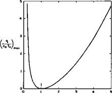
Consider now the more interesting case of compressible flows with heat addi­tion at high Mach numbers, where we can refer to the extensive summaries of present knowledge provided by J Zierep (1974) and E G Broadbent (1975), and where further references may be found. Some instructive results can be derived for a simple one-dimensional flow with addition of mass, momentum, and energy, where a number of different flows is possible, depending also on whether Mq > 1 or Mq < 1 . For Mq > 1 , in the absence of shockwaves or detonation waves, both energy addition and mass addition lead to a decrease in the velocity, whereas momentum addition produces an acceleration; for Mq < 1 , however, the opposite is true. Generally, the effects of mass and momentum addition are of the same absolute magnitude and may, therefore, cancel one another. Solutions of the conservation equations show, in particu­lar, that there is an upper limit to the amount of mass or energy that can be added to a steady stream and also an upper limit to the amount of momentum that can be removed from it. Thus we see again a qualitative resemblance between the addition of heat and of mass to compressible flows. If only heat is added, the maximum value of the amount of heat per unit mass turns out to be

Heat addition to airstrearns(8.26)

which is illustrated in Fig. 8.31. In the neighbourhood of Mq = 1 , only a small amount of heat can be added and this leads to a velocity equal to that

LIVE GRAPH

Click here to view

Heat addition to airstrearns

M0

Fig. 8.31 Maximum heat addition as a function of Mq

of sound: the flow is choked. This implies, for example, that not all the curves in Fig. 3.16 can be realised, but it will be seen that this is not a severe restriction in practice. We note that, if more heat is added than that given by equation (8.26), it is no longer possible to maintain a steady flow. The resulting unsteady flows have been investigated by F Bartlma (1963) and (1971).

Although considerations of onedimensional flows reveal some important features and effects of heat addition, what we really need are design methods for two­dimensional and for threedimensional flows, where heat is added continuously in the neighbourhood of solid bodies, possibly over some extended region. Before we discuss such methods in the next section, we may briefly consider the possibility of applying discontinuous flame fronts in a physically realistic manner.

Consider first a combustible mixture of a gaseous fuel and air at rest. Suppose a reaction between the two could be initiated in some plane and a flame front produced. This flame front, or deflagration wave, is a combus­tion process without pressure increase; it will propagate normal to itself by a process governed mainly by conduction of heat away from the flame front, which sets off new reactions. The speed of propagation of these deflagration waves is relatively low; for example, a plane flame will propagate at about 0.05m/s in a methane-air mixture and at about lOm/s in a gas consisting of 2H2 and 02 . On the other hand, the widths of the combustion zones are quite small; they are about 5 x 10“V and 5 x 10"6m respectively in the two cases quoted above. Now let such a deflagration wave be superposed upon a flowing fuel-air mixture. In general, the characteristic time and length scales implied in the chemical kinetics are quite different from those of the flow process, so that chemical kinetics and gasdynamics can be studied separately. However, in a propulsion system, the flame front should be stationary relative to the moving body, and it is difficult to think of a flowfield where the velocities are low enough to make it so in a system of reasonable size, unless extremely high angles of sweep of the flame front are contemplated, in which case the tangential velocity component along the flame front may well introduce some other mechanism in addition to heat conduction. Such a combustion process is particularly difficult to visualise in a

supersonic stream, so that deflagration waves are not very likely to find an application in hypersonic aircraft.

Next, consider the question of how chemical reactions can be initiated and maintained, at some fixed station in a supersonic premixed combustible stream of air and fuel, without changing the cross-sectional area of the stream involved. We think of a process where it is justified to assume that the chemical process is very much faster than the flow so that the characteristic length scale of the reactions is again very much smaller than a characteristic dimension of the flow. In other words we think of a process where the prob­lems of gasdynamics can again be separated from those of chemical kinetics and where, as far as the former are concerned, the addition of heat occurs at constant area and may simply be replaced by discontinuities in some of the functions of state. A physically meaningful process of this kind is obtained if the heat addition at constant area is combined with an ordinary shockwave just upstream of it. We may then assume that the temperature rise through the shock is large enough to initiate the chemical reaction. The combination of a shockwave and discontinuous heat addition at constant area is a detona­tion wave. A plane detonation wave propagates normal to itself at a speed which may be as high as the speed of sound behind it, i. e. it may travel

faster than the corresponding shockwave in a non-reacting gas and is, there­

fore, well suited for combustion in a supersonic stream. Its main drawback is, of course, that it can only exist in a flow which contains a combustible mixture and, therefore, a premixed stream must be provided. If the chemical kinetics of these processes are considered in more detail, it may be found that the reactions are delayed and occur some distance downstream of the shockwave. In this case, we may speak of shock-induced combustion. For our purpose, we make no distinction between such combustion and the detonation wave proper.

Some aspects of the changes of state involved in a detonation wave normal to

Heat addition to airstrearns Heat addition to airstrearns

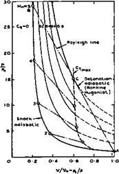
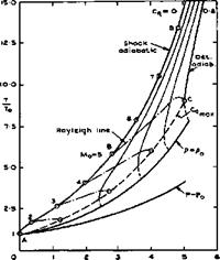
a stream with a Mach number Mq are illustrated in Fig. 8.32, where a

Fig. 8.32 Diagrams of state of a gas with heat addition at constant area

LIVE GRAPH

Click here to view

Подпись: C Heat addition to airstrearns Подпись: (8.27)

non-dimensional heat-input coefficient has been used, which is defined as

The diagrams have been drawn for an ideal gas, but this simplifying assump­tion is not necessary. The shockwave part of the detonation wave brings about a non-isentropic change of state from the initial conditions A to state B. The addition of heat is then another non-isentropic change from В to C along a so-called Rayleigh line. As is well-known, there is a limit to the amount of heat that can be supplied to an airstream at constant area. The maximum is reached when the Mach number behind the detonation wave is unity and this happens at the so-called Chapman-Jouguet point (shown as C in Fig. 8.32) where the Rayleigh line is a tangent to the Rankine-Hugoniot adiabatic for that amount of heat in the p, v-diagram. The Chapman-Jouguet point defines also the highest possible heat input and the dashed curves to the right of the line marked mv cannot be realised in a steady flow. Again, this does not impose a severe restriction in practice. We note that the pressure falls during the heat addition along the Rayleigh line although the overall pressure change through the detonation wave (from A to C) is a pressure rise. Comparing flow cycles with detonation waves and constant-area combustion with flow cycles with constant-pressure combustion (see section 3.6), for the same Mach number, compression, and heat input, we note that the pressure immediately behind the detonation wave is considerably lower than that behind constant-pressure combustion and that the temperature there is also less. However, temperatures and velocities at the end of the flow cycle, in the ‘jet’, are much the same in both cases and consequently also the thermal and propulsive efficiencies. The widening of the stream tube due to heat addition is also much the same in both cases.

Details about these matters may be found for instance in J Zierep (1974) and D Ktlchemann (1965), where oblique waves are also discussed which are more relevant to hypersonic propulsion than the normal waves assumed in Fig. 8.32. As in the case of plain shockwaves, only the velocity component normal to the wave front is changed and the tangential component remains the same, the normal component following the rules of onedimensional flows. With К Oswatitsch (1966), we may make a distinction between nominally subsonic and supersonic plane wave fronts, in a supersonic mainstream, depending on whether the front is more highly swept or less swept than the Mach lines. This dis­tinction is analogous to that made in wing theory, as discussed in section

6.3, equation (6.37). Subsonic fronts have an upstream influence up to the relevant Mach line, and the normal velocity component can be increased or decreased, depending on the heat input. Thus the velocity vector may be turned either way, away from the mainstream direction. The normal velocity component is always decreased by a supersonic front, so that the velocity vector is turned towards the front. J Zierep (1967) has given an interesting relation for the change of the velocity component Vx in the mainstream direction, which holds for both subsonic and supersonic wave fronts, swept through an angle ir/2 – a :

Heat addition to airstrearns(8.28)

The first term on the right-hand side is the well-known Ackeret term for shockwaves without heat addition. This demonstrates very clearly the effects

which the various parameters have, bearing in mind that – 1 = cot u,

where у is the Mach angle as defined by equation (3.43) and Fig. 4.66.

In general, however, detonation waves do not exist in midair but are anchored to a wait at some point where the slope changes appropriately. Therefore, we shall continue this discussion when we come to complete flowfields in the next section.

Work is also being done on engine nacelles, on the assumption that hypersonic aircraft will be powered by separate propulsion units. We refer here to the interesting theoretical and experimental investigations by P Contensou et al.

(1973) , which led to a dual-mode ramjet with alternative subsonic or super­sonic combustion in the same chamber. This permits one to obtain a perform­ance near to that of a continuously adaptable ramjet for flight up to Mach numbers of 6 or 7, while retaining a fixed geometry for the air intake and for the nozzle during the whole mission. It may be possible to adapt these principles also to the integrated propulsion of waverider aircraft.

Effects of viscosity

Flows at hypersonic Mach numbers can bring about drastic changes in the effects which viscosity can have, especially when the air can no longer be treated as a perfect gas and the so-called real-gas effects must be taken into account. But we have already seen that the wave­rider aircraft we have in mind are not likely to penetrate deeply into flight regimes where the speeds and temperatures are so high that real-gas effects

dominate the flow. Therefore, we are primarily interested in flows where effects of viscosity can still be assumed to be confined to boundary layers in perfect gases. But, in such boundary layers, there are now significant gradients normal to the surface not only of the velocity but also of the temperature, T, and the density, p. The basic theory of such boundary layers is well-developed, and we refer here to textbooks by H Schlichting

(1960) , A Walz (1969), and R N Cox & L F Crabtree (1965) and to an extensive survey by R Michel (1968), where further references may be found.

Подпись: Pr Подпись: (8.23)
Effects of viscosity

Apart from the introduction of two further variables, T and p , we must also include the possibility that the viscosity, у, the thermal conductivity, к, and the specific heat of air, cp, are all functions of the absolute temperature. Thus we have to consider a further non-dimensional parameter to characterise heat transfer, in addition to the Reynolds number and the Mach number. A suitable parameter is the ratio between the rates of diffusion of vorticity and of heat, which is called the Prandtl number and defined as

The numerical value of the Prandtl number for air at room temperature is about 0.7, which is not far from a value unity that leads to some simplifications.

Effects of viscosity Подпись: (8.24)

In fact for twodimensional steady laminar flow with Pr = 1 , the boundary – layer equations give the same function of z for both the velocity profile Vx(z)/Vq and the temperature profile T(z)/Tq, so that the thicknesses of the velocity and thermal boundary layers are then identical. This is the so – called Reynolds analogy, which postulates that heat and momentum are trans­ferred by the same mechanism, and which is often assumed to hold also in turbulent flows and when the Prandtl number is not unity. If we measure the heat, qw, transferred across unit area to or from a wall at the temperature Tw from or to a stream at the temperature To by the non-dimensional Stanton number

the Reynolds analogy states that

Подпись: (8.25)St = JCf T

w

where C, = ■ –s-

К

Effects of viscosity

is the skin-friction coefficient. These simple relations indicate at least that it is worthwhile to investigate heat transfer and skin friction together. Considerations of similitude also play an important part in hypersonic aero­dynamics (see e. g. L Lees (1953), W D Hayes & R F Probstein (1959), J Zierep (1971)). Some phenomena depend not only on Mach number and Reynolds number separately but only on a combination of the two. For example, hypersonic flowfields may depend primarily on a parameter proportional to Mg/i^Re. Another significant parameter is

which can be shown to be proportional to the boundary-layer thickness. These considerations indicate that viscous interactions between the boundary layer and the external flow become more and more important as the Mach number increases.

In this section, we shall discuss some effects of viscosity, which have a bearing on the design of waverider aircraft with aerodynamically sharp lead­ing edges:

skin friction, aerodynamic heating, and displacement effects in attached boundary layers;

conditions which may lead to flow separations, and possibly reattachment, and the consequences of such flow phenomena;

a brief digression into some problems of re-entry vehicles, in as much as they may reveal and clarify effects in a strong manner, which may occur weakly also on waverider aircraft;

flows with injection of a different gas and boundary layers with injection or suction;

effects of heat conduction in the body, especially near the sharp leading edges of waveriders.

This selection of topics evidently covers only a small portion of the field of conventional hypersonics, which is dominated by blunt-body aerodynamics. Thus we shall not discuss a kind of interaction, which is typical of blunt – body flows, and which is caused by the vorticity generated in the stream out­side the boundary layer by a highly-curved bow shock. This vorticity may have a strong influence when it is of the same order as the average vorticity in the boundary layer associated with the shear stress. We assume here that such conditions may largely be avoided in the design of waverider aircraft. But strong viscous interactions may also occur on wings with sharp leading edges, especially at the moderate Reynolds numbers frequently encountered in test facilities. We refer here to the work of J C Cooke (1964) and L Davies

(1970) on how possible changes in the viscous-induced force and moment characteristics may be estimated. Note that the full-scale Reynolds number is likely to decrease with Mach number, mainly because the flight altitude is expected to increase (from around 25km at Mq = 5 to around 35km at M0 = 10).

We have already mentioned some of the many methods for calculating the development of compressible boundary layers in earlier chapters. For laminar layers, we refer especially to the methods by С C L Sells (1966), С В Cohen & E Reshotko (1955), and N A Jaffe & A M 0 Smith (1972). Such methods can, in principle, be extended to apply to regions of strong interaction between the boundary layer and the external stream, by simultaneous solution of the boundary-layer equations together with a relation between pressure and flow direction at the edge of the boundary layer obtained from the isentropic flow equations. L Lees & В L Reeves (1964) have derived one such method based on the boundary-layer integral equations for momentum and moment of momentum, and have used it to give successful predictions of shock-induced separation and reattachment. Subsequently, J M Klineberg & L Lees (1969) extended the method to apply to flows with heat transfer. When the boundary-layer equa­tions are coupled in this way with a relation between pressure and flow direction at the edge of the boundery layer, a singularity arises that was discussed in both these papers. In consequence it was found necessary to distinguish between subcritical and supercritical viscous flows in their methods. J L Stollery & W L Hankey (1970) have shown that, by using a simpler boundary-layer method, the critical boundary that arises from the equations can be removed from the domain of practical interest, and is there­fore, they argue, of no physical significance. A W Bloy HP Georgeff

(1974) have found that the method of Klineberg & Lees gives good agreement with their measurements of surface pressures and heat transfer rates in two­dimensional flows over sharp compression and expansion corners at Mg = 12 , and В G Gautier & J J Ginoux (1973) have modified it to compute viscous interactions over a continuous range of ratios between wall and stagnation temperatures. They found satisfactory agreement with experimental results for twodimensional flows over flat plate-wedge models with widely-different wall cooling rates, and their method may be regarded as a significant improve­ment over previous attempts to calculate viscous interactions where the wall temperature distribution is prescribed. E H Hirschel (1975) had discussed various methods concerned with boundary layers or boundary-layer-like flow – fields at high Mach numbers, which are dominated by viscosity rather than displacement effects, and where strong pressure gradients normal to the sur­face may occur. He has derived the general equations governing such flows and recommends the application of finite-difference rather than integral methods for their solution.

For turbulent boundary layers, we refer to calculation methods by J C Rotta

(1959) , L F Crabtree et at. (1965), J E Green (1972), D В Spalding & S W Chi (1968), H Fernholz (1969) and (1971), К G Winter & L Gaudet (1970), P Bradshaw & D H Ferriss (1971), and J E Green et at. (1972). It cannot yet be said that the relative accuracy of these methods has been assessed, even for two­dimensional flows at fairly low Mach numbers. Some theoretical as well as experimental uncertainties remain unresolved, as has been demonstrated, for example, in carefully-executed yet incomplete experiments on a flat plate by D G Mabey et at. (1974). They found that the measured velocity profiles can be fitted very closely to the family of theoretical profiles proposed by Rotta; and that the technique developed by J M Allen (1968) for estimating skin friction is fairly accurate. The flat-plate skin-friction laws of Spalding & Chi and of Winter & Gaudet are in fairly good agreement with the measurements but significant deviations become apparent when the Mach number is increased (to the still relatively low value of 4.5). The measurement of temperature profiles still presents some difficulties, but there are now well-established techniques for measuring heat transfer to the wall (see e. g.

D L Schultz & T V Jones (1973) and К G Winter et at. (1975)). Available techniques for measuring the total temperature profile through the boundary layer have been examined by G Drougge & G Hovstadius (1975) and their accuracy assessed. Measurements by existing probes of different designs have been made, both simultaneous measurements in a given facility and comparative measure­ments with the same probe in different facilities. In general, the agreement between the various probes is good, but some unexplained anomalies remain.

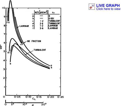
For caret wings, the overall skin-friation drag Сцр does not vary much with Mach number if it is measured as a fraction of the total drag Cj)m reached when L/D has maximum value which, in turn, is generally close to. the L/D – value at the design condition. For relatively thin •wings (t « 0.04), the skin friction share is about 1/3 of Срщ and thus about the same as that for slender wings at supersonic speeds. But it is only about 1/5 for thicker lifting bodies (t «0.1) which have a higher pressure drag. Thus skin
friction matters relatively less on thick lifting bodies than on any other type of aircraft, and the emphasis is shifted towards the problems arising in connection with aerodynamic heating and with the achievement of natural laminar flow.

Uncertainties in estimating skin friction and heat transfer become consider­ably greater when the flow is threedimensional. We must then rely mainly on experimental data, and there are not many of these. Tests on delta wings are relevant in the present context, and we refer to those by H Thomann (1962) and A L Nagel et al. (1966). Some typical results of heat-transfer measure­ments by A J Edwards (1975) on the compression side of a flat-cropped, delta wing are reproduced in Fig. 8.18 (for Re = 1.4 * 10^, Mq = 8.2) . The heat
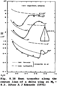
Подпись: */* Fig. 8.18 Heat transfer along the centre line of a delta wing at MQ = 8.2. After A J Edwards (1975) LIVE GRAPH

Click here to view transfer along the centre line of the model is given in form of Stanton numbers. The outstanding feature of the results is the large variation of St along the chord, especially at the higher angles of incidence. This may be attributed to transition from the laminar to the turbulent state, which typically takes a considerable length to be completed. This can clearly be seen by comparison with the curves calculated according to L F Crabtree et al• (1965). Transition is probably caused by the sweeps or crossflow, instability described by W E Gray (1952, unpublished) and P R Owen & D G Randall (1952).

G T Chapman (1961) has shown that their criterion remains valid also in super­sonic flows. At a ■ 0 , the boundary layer appears to be laminar over about 2/3 of the length. Transition moves gradually forward as the angle of incidence is increased. Very roughly, the ‘transition line’ is parallel to the leading edge at some constant distance downstream of it.

Thus the state of the boundary layer is of considerable importance not only for lift and drag, as we have already seen in connection with Fig. 8.4, but also for heat transfer. Unfortunately, the transition process is still imperfectly understood and transition Reynolds numbers are difficult to measure and to calculate, as they depend on many factors. Here, we can refer only to a few of the many papers on the subject, such as those by В E Richards & J L Stollery (1966), J L Wilson et at. (1969), and to the very extensive review by M V Morkovin (1968). Generally, in the range of Mach numbers of interest here, transition Reynolds numbers between about 106 and 10^ have been measured, but higher values up to about 3 x 10? have also been found. It appears that the transition Reynolds number, based on conditions at the edge of the boundary layer and on the distance from the leading edge to the mid­point of the transition zone, increases as the flight Mach number increases. Heat loss from the surface by radiation or conduction has the effect – within certain limits – of increasing the transition Reynolds number still further: typically, the combined effects of Mach number and heat loss may increase the transition Reynolds number by an order of magnitude between subsonic speeds and a Mach number of about 10. Yet another effect of the Mach number on the laminar boundary layer is to decrease its sensitivity to roughness (see e. g.

J L Potter & J D Whitfield (1962)). Again, typically, the size of roughness to have a significant effect on the transition Reynolds number on a flat plate may increase by an order of magnitude between subsonic speeds and a Mach number of about 5. For these reasons, hypersonic flight speeds offer the prospect of higher transition Reynolds numbers than those obtained at lower speeds, without special attention to surface finish. It may be possible to achieve natural laminar flow over large parts of the surface, without all the accessories which usually detract from the potential advantages of this type of flow. J R Collingboume & D H Peckham (1966) have considered these matters in some detail and conclude that even all-laminar boundary layers on both surfaces of a caret-like aircraft may be a feasible prospect for a relatively small aircraft (of a weight of about 200kN) with a low wing load­ing at cruise (of about 1.2kN/m^) at a Mach number of about. 10; the associated surface temperatures may be about 600°C or less.

In this context, the flow near the leading edges needs special consideration. The pressure field may be such that the flow within the boundary layer is directed inwards whereas the streamlines at the edge of the boundary layer may be deflected outwards. These crossflow conditions produce longitudinal vorticity which contributes to instability and reduces the transition Reynolds number. Now, the leading edges of the waverider aircraft discussed here are intended to be nominally sharp, but will have a certain finite radius in practice. Collingboume & Peckham have estimated values of the critical nose radius below which heat-transfer rates should correspond to theoretical values for a laminar boundary layer, and above which the heating rates exceed these and hence, it is inferred, transition to turbulent flow has begun at the attachment line along the leading edge. For a caret-wing aircraft with s/Я = 0.3 and a wing loading of 1.2kN/m*, they estimate the critical nose radius to be about 1.5cm at Mg = 5 , and about 2.5cm at Mg = 10 . It may be feasible to achieve these small values in practice. The structural implications of this will be discussed further below.

The actual temperature at the attachment line along a swept cylindrical lead­ing edge may be estimated, for example, by a method developed by I E Beckwith & J E Gallagher (1961). The results have been found to be in good agreement with experimental results obtained by A Naysmith (1971) in free-flight tests on a caret wing with rounded leading edges.

Returning to the compression surface of wings, we note from the results in Fig. 8.18 that even a simple strip theory, based on calculations for two­dimensional flows by L F Crabtree et at. (1965) can represent at least the general trends fairly well, if the state of the boundary layer is known. The method of D В Spalding & S W Chi (1968), applied in this way, gives similar results. But A J Edwards observed significant threedimensional effects away from the centre line, which cannot readily be predicted. Strip theory, based on local distances from the leading edge, has also been applied to experi­mental results on caret wings with some success by J Picken & G H Greenwood (1965), R A East & D J G Scott (1967), and G H Greenwood (1971) and (1974). Greenwood tested a caret wing with a right-angle comer at the ridge line at speeds up to Mg = 4 and found that the heat-transfer rates in the immediate vicinity of the comer are reduced to about 60% to 70% of the level away from the corner, where the measured heating rates are in good agreement with estimates from a strip theory, based on results for the twodimensional turbu­lent flow over a flat plate. This strong and favourable comer effect may be associated with the near-conical nature of the flow, which was probably coni­cally subsonic under the test conditions. The opposite effect has been found by H Pfeiffer & H J Schepers (1974) in tests near a streamwise right-angle corner between two flat plates with sharp unswept leading edges. There, streamwise vorticity and an associated secondary shockwave near the comer increase both skin friction and heat transfer substantially. These effects may be of considerable practical importance and require much further elucida­tion. But we may conclude in general terms which kind of corner should be avoided in aircraft design and which may be used in engineering applications.

We can now consider the boundary-layer characteristics of caret wings in some more detail to get at least a notion of what the main effects may be.

J R Collingbourne & D H Peckham (1966) have investigated the broad effects of the shape, wing loading, flight altitude, and transition Reynolds number on skin friction and on the aerodynamic efficiency of caret wings. Calculations for both laminar and fully-turbulent boundary layers have been carried out by D Catherall (1962) and (1964), who determined the displacement thickness, the shear stress, and the temperature at the wall for a number of design cases.

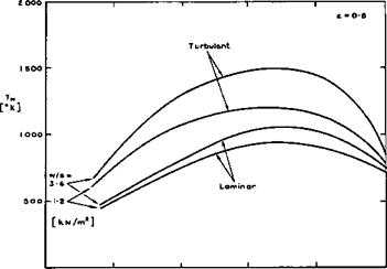
In general, in the Mach number range of interest here, the displacement thick­ness can be expected to be small compared with the dimensions of the body, and the interference effects between the two sides of the compression surface may not be large and may possibly be favourable. C S Sinnott (1963) has carried out extensive calculations of the temperature at the wall for turbu­lent boundary layers under conditions of equilibrium between convective heat transfer to the wall and heat radiation away from it. The emissivity factor has been taken as є – 0.8 in the examples quoted below. It emerges that the surface temperature on the compression surface depends mainly on the wing loading (see equation (8.10)) and not so much on the altitude of flight, above an altitude of about 30km. It is, therefore, possible to obtain a rough guide to the surface temperature to be expected by plotting this nearly – constant value against the flight Mach number for various values of the wing loading.

An example is shown in Fig. 8.19 for the temperature at a station which lies about 10m downstream of the leading edge. Upstream of this station, the temperatures are higher and downstream they are lower. We find that the temperatures increase substantially with Mach number. That they fall again at higher Mach numbers is caused by the fact that account has been taken of the centrifugal forces acting on the mass of the aeroplane, which allow a reduction in the lift to be obtained from the compression surface. But this

LIVE GRAPH

Click here to view

Effects of viscosity

О З Ю lb 20 25

Me

Fig. 8.19 Equilibrium wall temperatures. After Sinnott and Catherall

occurs beyond the range of Mach numbers we have in mind for waverider air­craft. We note that the temperatures are generally not high enough to bring in real-gas effects in a major way; they may matter only in localised regions. We note especially the large differences between the temperatures in turbulent and in laminar boundary layers. In view of the considerable heating problem which these aircraft are bound to have, it is vitally important to know not only the development of the boundary layer to a high degree of accuracy but also where у and in what way> transition occurs. For example, if the boundary layer remained turbulent, then the surface temperature would increase con­siderably if the flight Mach number were increased from 5 to 10. If, on the other hand, the boundary layer was turbulent at Mq – 5 but fully laminar at Mo = 10 , then the surface temperature would remain roughly constant through­out this Mach number range.

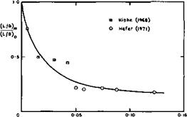
Some instructive experimental results for flows where the effects of viscosity Were especially large have been provided by G Hefer (1971). He tested a caret wing designed for a Mach number of 8.5 at that and at higher Mach numbers up to 12 in a rarefied airflow down to Reynolds numbers of 5000, so that the rarefaction parameter M(j//Re exceeds 0.1. The displacement flow caused by the boundary layer can then be quite large so that the basic angle of the wedge is effectively increased and the shockwave displaced outwards from the plane of the leading edges. However, the pressure distributions, as influ­enced by the viscous interaction, are comparable with results obtained from a theory for twodimensional flow. The lift coefficient in particular, can be estimated as for a wedge in inviscid flow, once the displacement surface is known, even at these low Reynolds numbers. The drag coefficient, on the other hand, is considerably increased by the effects of viscosity. An example is shown in Fig. 8.20, where the maximum lift-to-drag ratio is plotted as a fraction of that estimated for inviscid flow. Hefer*s results are consistent with those obtained by К Kipke (1968) and (1970), and it will be seen that the reductions in aerodynamic efficiency can be very large. We may conclude from this that hypersonic aircraft should preferably be designed to avoid the rarefied flow regime and to keep the rarefaction parameter very small.

Effects of viscosity

Мо/ТЙЇ

-Fig, 8.20 Experimental lift-to-drag ratios of caret wings

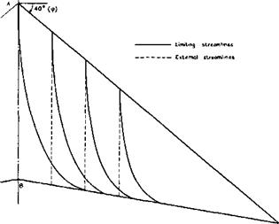
We now proceed to consider some flows where the pressure field may be such that flow separations may occur. An interesting example is the flow over the Townend surface (see Figs. 3.10 and 3.11), where the pressure behind the compression waves is not uniform so that the boundary layer development differs essentially from that along a flat plate. This boundary layer is remarkable in that it develops spanwise crossflow components even though the external streamlines are straight in plan view, because there are spanwise pressure gradients. J C Cooke & О К Jones (1964) have obtained an approxi­mate solution for the laminar boundary layer along a Townend surface. The threedimensional flow in the boundary layer is still relatively simple because of the conicality of the flow about the tips of the compression sur­face. In particular, the limiting streamlines in the surface cross each ray from the tips at the same angle. Thus they all curve outwards as indicated in the example shown in Fig. 8.21. This curvature leads, in the first place, to a possible sweep instability of the laminar boundary layer, as discussed above. In the second place, separation may occur because the pressure field

Effects of viscosity

Fig. 8,21 Streamlines over a Townend surface at Mq = 6.8. After Cooke and Jones

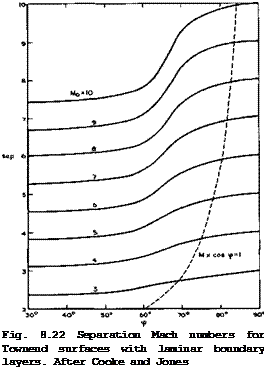
Подпись: Fig. 8.22 Separation Mach numbers for Townend surfaces with laminar boundary layers. After Cooke and Jones
Effects of viscosity

is wholly unfavourable, in the sense as defined by E C Maskell & J Weber (1959), because the pressure rises streamwise and inwards. If separation occurs as a consequence of the limiting streamlines forming an envelope, this separation line must lie along a ray from the tips, in this particular flow. Although the crossflow is not normally small near the separation line, the calculation has been carried through to separation and a Mach number, Msep, has been determined down to which the flow can be retarded before separation occurs for given mainstream Mach numbers, Mq, and angles of sweep, ф, of the line where compression begins. An example is shown in Fig. 8.22. We

find that very highly swept initial compression lines in a conically subsonic flow regime appear to lead to early separation of the laminar boundary layer, whereas a useful amount of compression may be obtained if the initial com­pression line is not so highly swept. For instance, with an initial Mach number of 10, a compression down to about Mj = 7.5 may be obtained, corres­ponding to a compression ratio of about 6.6. The separation Mach number is not directly related to that obtained in the corresponding twodimensional flow, as it is in the case of swept wings. The corresponding twodimensional values appear here as the limit ф •+■ 0 . These results have not yet been subjected to experimental tests, and the behaviour of turbulent boundary layers is not known.

Actual flight vehicles may have many regions of high compression that can cause boundary-layer separation and, possibly, reattachment. These are of special interest because of the very high heating rates that may arise locally. In a conventional layout with distinct wings, fuselage, engines,

and control surfaces, such regions include deflected flaps, shock interactions in inlets, blunt fins or other protuberances on fuselage or wing, axial comers in inlets, wing-body and wing-fin junctions, and such regions at the leading edge of wing and fins, which are subjected to the impingement of shockwaves from the fuselage or other forward components. Note that all these interactions must be expected to be highly threedimensional. An exten­sive review of these problems and of available methods for predicting and for dealing with these effects has been given by R H Korkegi (1971) who concludes that, in the final analysis, the severity of heating caused by viscous inter­action may be such that it is far more desirable to design around them than to attempt to cope with them through weighty replaceable ablation shields or equally bulky and sophisticated forms of cooling. This is another strong reason why we want to concentrate here on design methods for integrated wave – rider shapes, where many of these interference problems do not occur. But not all of them can be avoided altogether, and one that has to be faced is that introduced by the deflection of control surfaces and attendant flow separations.

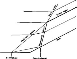
Separations induced by a sudden change in the inclination of a wall have been studied for a long time, mostly for twodimensional flows. The change in flow direction is communicated through the boundary layer upstream of the comer and may induce a separation of the boundary layer and subsequence reattach­ment. This flow is somewhat related to the flow in Fig. 4.64, where a shock­wave interacts with a boundary layer, but here the prescribed directions of the wall constrain the flow more firmly. The simplest model of a two­dimensional flow, where the result of the separation is a bubble, is sketched in Fig. 8.23. All the streamlines and also the surface of separation are

Effects of viscosity

Fig. 8.23 Schematic model of a flow near a corner

assumed to be straight, as are the shockwaves. There is at least one up­stream shock, adjusting the flow to the change of direction near the separa­tion line, and one downstream shock, adjusting the flow near the attachment line. These two branches intersect and continue as a single main shock into the stream. The flows that pass on either side of the intersection line should suffer the same pressure rise and the same overall change in direction, but it cannot be expected that the actual velocities should also be the same. Therefore, a shear layer or vortex sheet must be introduced downstream of the intersection line. This type of flow has been studied theoretically and experimentally by F Wecken (1949) and N H Johannesen (1952), and E Eminton

(1961) has shown that a solution for a simple flow as in Fig. 8.23 exists only for a very limited range of Mach numbers – for each angle. She concluded from her experiments that the actual flow remains similar to that in Fig.

8.23 but that it is determined by the viscous effects around the feet of the branches, and that the external inviscid part of the flow appears to be able to accommodate itself readily by small deviations from the simplified model. This means that we must expect that Reynolds number and Mach number have strong effects on this type of flow, including conditions for the pressure rise needed to cause separation. This flow is also related to flows up a step or down a step and to base flows, which have already been discussed in section 5.9. All these have been extensively investigated, experimentally and theoretically, and there are various criteria for incipient separation to occur, depending on the initial state of the boundary layer, and for estimat­ing the development of the separated flow. We mention here the work of M J Lighthill (1953), D R Chapman et at. (1957), J C Cooke (1963), L Lees &

В L Reeves (1964) and J M Klineberg (1969). P Carrifere et al, (1975) have given an extensive summary of the various methods for calculating turbulent separated flows. In the end, however, we must rely on experimental data, especially when threedimensional effects play a part. Valuable results for the pressure and the heat transfer in separated and reattached flows at relatively low Mach numbers (up to 4) have been obtained by J Picken (1960) by means of the free-flight technique (see also J Picken & D Walker (1961)).

Out of the many other experimental investigations we refer here to the systematic work done on turbulent boundary layers at Mach numbers between 3 and 9 carried out at the Imperial College. This work has been summarised by J L Stollery (1975) who also reviews earlier theoretical and experimental developments in this field. The work includes tests by G T Coleman et al.

(1971) and (1973) on attached boundary layers along flat plates, which showed that the method of H H Fernholz (1971) gives the most reasonable overall pre­diction, although it gives the opposite trend of skin friction with wall temperature ratio to that generally accepted. A comprehensive and critical assessment of the accuracy of all the available prediction methods is still outstanding. Further tests by D M Rao (1970) and (1975), G M Elfstrom (1972), G T Coleman & J L Stollery (1972), and A J Edwards (1975) are concerned with attached and separated flows in compression corners and include tests on delta wings with trailing-edge flaps on the lower surface, deflected downwards.

A schematic summary of the various effects of the Reynolds number on the flow characteristics is shown in Fig. 8.24. Only the separation and reattachment shocks are shown; at higher Mach numbers, their intersection may not be rele­vant to the viscous flow near the comer. This diagram indicates again how important transition is in these flows. As an example, Fig. 8.25 shows the heat transfer on a delta wing with flap, which is to be compared with the results for the plain wing in Fig. 8.18. The heat transfer rises steeply in the separated region and reaches a peak near the attachment line. When the flow is turbulent, the heat transfer reaches a plateau in the separated region and then rises rapidly again to a peak near reattachment. This peak heat-transfer rate may exceed the value at the stagnation line in two­dimensional laminar flow. The pressure distribution which determines – the control forces and moments achieved by the deflected flap, follows a curve which is closely similar to the heat-transfer distribution, again with a high peak near the attachment. We note from Fig. 8.25 that theoretical estimates for twodimensional flow give a rough qualitative indication of the heat – transfer levels along the centre line of the wing, but significant
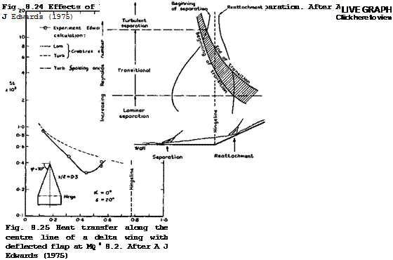
Effects of viscosity

threedimensional effects have also been observed. For a critical review of the various criteria put forward to predict initial separation in laminar and turbulent boundary layers subjected to weak and strong interactions with shockwaves we refer again to J L Stollery (1975). One of his conclusions is that an oblique shockwave penetrates well into the boundary layer, and that

it is convenient to divide the layer into an outer, primarily inviscid but rotational, zone and a thin inner viscous layer, as in the flow model proposed by G M Elfstrom (1972).

These flap-induced flow separations are so important because their upstream influence can extend very far. This can be seen from the examples in Fig.

8.26 from tests by L Davies (1970), D M Rao (1970) and (1975), and A J Edwards

(1975) , where x = xs. The difficulties in predicting this become apparent from the spread of the data, with no obvious systematic trends.

Effects of viscosity

LIVE GRAPH

Click here to view

Similar separations have been observed in axisymmetric flows when a flare is put on a body of revolution. According to D И Kuehn (1961) and G T Coleman &

J L Stollery (1974), the deflection angle to cause incipient separation is slightly higher in axisymmetric flow than in twodimensional flow. There is again a close similarity between the surface-pressure and heat-transfer-rate distributions in the two cases. This suggests that criteria evolved from the large amount of information available for these relatively simple flows may be used as a guide in the design of control surfaces for hypersonic vehicles.

We mention that attempts are being made to deal with more complex flows in a unified manner (see e. g. R N Gupta & С M Rodkiewicz (1975)) and to treat unsteady flows (see e. g. D Rues (1973) and W Schneider (1974)).

There is very little evidence about viscous effects and especially aerodynamic heating on the lee side of lifting bodies. Windtunnel tests by H Thomann

(1962) and free-flight tests by J В W Edwards (1965) and by G H Greenwood (1968) on delta wings with nominally subsonic and supersonic leading edges were all made under flow conditions where vortex-sheet separation from the leading edges occurred. It was found that the magnitude and distribution of heat-transfer rates to the surface follow again very closely those of the local surface pressures. The method of L F Crabtree et alm (1965) can be applied to predict heat transfer quite successfully if local flow conditions,
derived from the measured local pressures, are used. If the same method is applied, using flow conditions appropriate to the free stream, then measured values lie well below those calculated for the corresponding flat plate, especially in the region underneath the vortex sheets; they come nearer to these values in the middle region between the attachment line. Generally, the peak heating rates decrease with increasing sweepback angle but the rates near the leading edge increase. Vortex-type flows were also observed by A H Whitehead Jr (1970), D M Rao (1971), and D M Rao & A H Whitehead Jr (1972), but the implications are not yet clear.

We digress now to consider very briefly another possible application of the waverider design principle: that is to vehicles suitable for lifting re-entry into the atmosphere and, in particular, to space shuttle orbiters. This application was proposed by L H Townend (1970) and has been supported by theoretical work by L C Squire (1971) and (1975) and put to the test in many experimental investigations, e. g. by L Davies et at. (1971), R Houwink (1972)

В E Richards (1973), G T Coleman (1973), R W Jeffery & J К Harvey (1974), and R J Stalker S J 1 Stollery (1973) and (1975). The tests were carried out at high Mach numbers and very high angles of incidence, appropriate to lifting re-entry conditions. The waverider shapes with sharp edges and recessed undersurfaces are exactly opposite to the convex shapes with highly rounded leading edges commonly thought suitable for this purpose. The main advantage of bodies with recessed undersurfaces stems again from the fact that the flow may be contained and crossflow and spillage around the edges prevented or reduced. This means that, during re-entry itself, substantially higher lift coefficients (both per unit lift-to-drag ratio and maximum lift) can be generated as compared with, say, a flat-bottomed delta wing. This may lead to lower rates of heat transfer since deceleration may occur at higher altitudes so that, for a given flight speed, ambient and local air densities are lower. In addition, it has been found that the heat transfer to the wave­rider is less than that to the delta wing, from which it was formed, under similar flow conditions, by up to about 30Z at Mq = 20 (R W Jeffery &

J К Harvey (1974)). The theory of L C Squire (1967) gives good answers and, when suitably applied, can provide good predictions also of results obtained in high-enthalpy flows by R J Stalker & J L Stollery (1975) in a Stalker-Tube where significant non-equilibrium effects could be measured. The waverider may also offer better manoeuvrability and, after re-entry, it may glide hypersonically at higher lift-to-drag ratios than bodies of other shapes and thus improve the range and the cross-range. We already know that we can expect good flying characteristics at low speeds*. In his designs, L C Squire

(1975) has shown how extreme caret shapes may be avoided and how more practi­cal layouts may be obtained and further aerodynamic advantages gained by going to curved concave lower surfaces. When such bodies are put into a free mole­cular flow, multiple interactions of the diffusely reflected molecules occur since any point on one side of the lower surface can be seen from any point on the other. Explicit solutions for the flowfield of neutral atoms have been given by W Wuest (1975) and applied to caret wings. The waverider design principles have not yet been applied in practice.

The acute heating problem of hypersonic vehicles has led to an intensive search for means of cooling the surfaces. Aerodynamically, this can be

* We may note that the wings of a shuttle will still have a high temperature when they land on return. Windtunnel tests by J F Marchman III (1975) indicated that such heating may increase the drag of the wing; but no effects were detected on the development of the leading-edge vortices nor on lift and pitching moment.

achieved very effectively by injecting cool air or some other gas into the boundary layer. This can be done in various ways: by injecting a secondary gas through one or more slots into the mainstream (film cooling); by inject­ing a secondary gas through a porous surface (transpiration cooling); or by the gaseous decomposition products of ablating materials (ablation cooling).

In every case, the injection of a cool gas into the boundary layer not only cools the surface but also reduces the skin-friction coefficient. But this does not imply that the drag is necessarily reduced: by injection, or suction, the overall drag of a turbulent boundary layer may be higher than that caused by skin friction alone, as has been shown by J В Edwards (1961).

Many of the available theoretical and experimental investigations of turbulent boundary layers with fluid injection have been reviewed by L 0 F Jeromin

(1970) who gave an extensive list of references which is not repeated here.

Effects of viscosity Подпись: F Подпись: pwVzw p0Vx0 Effects of viscosity

We reproduce in Figs. 8.27 and 8.28 some of his collections of typical experi­mental results for the reductions of skin friction and of heat transfer by air injection through a porous surface, where the shaded areas give a rough indication of the experimental scatter. The parameter

is a measure for the rate of injection. These reductions can be quite sub­stantial. It should not be deduced from this particular way of plotting the results that fluid injections becomes less effective with increasing Mach number: for example, a plot of Cf/Cfo against F gives very roughly about the same reduction of the skin-friction coefficient due to injection independ­ent of the Mach number. Jeromin also discusses work on the injection of gases other than air. The injection of a light gas, such as helium, gives much bigger reductions of skin friction and of heat transfer because the smaller molecular weight leads to the formation of a layer of reduced density and viscosity close to the wall. In such layers consisting of different gases, diffusion processes and their measurement present additional problems. These have been investigated e. g. by W Wuest (1962), E Krause (1966), S V Patanker & D В Spalding (1967) and E Krause et al. (1972), where a detailed discussion of theoretical and experimental results may be found. Other work by P A Libby (1962), A Kumar & A C Jain (1973), and К Gersten & J F Gross (1973) deals with various other aspects of mass injection. The work of F L Fernandez & L Lees

(1970) is especially concerned with the effects which the finite length of a twodimensional flat plate with distributed injection may have. A special problem arises from the fact that, if the conventional boundary-layer assump­tions of constant pressure throughout are made, a particular value of uniform injection rate exists, beyond which no theoretical solutions can he obtained, as has been shown by 0 Catherall et al. (1965). Fernandez & Lees employ the method of В L Reeves & L Lees (1964) to demonstrate that, as injection is increased, the velocity profiles become inflected, the sonic line moves away from the wall, and the flow becomes subcritical. The effect of termination of injection can then be felt upstream of the end of injection. In particu­lar, as injection rates approach the maximum value which can be entrained by a constant-pressure mixing layer, virtually the entire blowing region experi­ences a falling pressure due to the effect of finite length. This effect provides for a smooth transition from a boundary-layer flow to one where mixing is negligible, except in a thin layer near the streamsurface which divides the injected and the mainstream gas. The general prospects for the active cooling of hypersonic transport aircraft have been reviewed by J V Becker (1971).

Another powerful means of cooling is the ejection of a stream of gas out of the ТЮ8Є of a blunt body, where cooling is most needed. The flow is similar to that discussed in section 5.2 in connection with Fig. 5.5(a) and its main feature is the supposed existence of a free stagnation point upstream of the orifice. The aim is at designing shapes which allow a steady flow like that sketched in Fig. 8.29 to be maintained: the ejected gas is to remain attached to the surface and turned through about 180°: the free stagnation point should remain in a fixed position in the subsonic part of the flow behind the

Effects of viscosity

Fig. 8.29 The model of Eminton for the flow out of a forward-facing orifice

detached curved shockwave typical of blunt body flows. It is instructive to follow the steps which have been taken in the aerodynamic design of such shapes to reach this aim, at least in part. In early experiments by H M McMahon (1958) and CHE Warren (1958), the flow was found to be highly unsteady because the ejected gas separated from the wall of the orifice and formed a jet. Where the jet reattached to the surface, the heat transfer was high, as to be expected. McMahon put a nearly vertical ‘deflector cap’, upon which the stagnation point could rest, upstream of the orifice and success­fully steadied the flow, in a manner similar to the effect of the horizontal ‘splitter plates’ of D M Heughan (1953) in the region of a rear stagnation point. However, this only shifted the problem to that of cooling the cap. Warren put swirl into the flow in the ejection pipe, which caused less dis­turbance to the mainstream but did little to reduce the temperatures around the nose. S H Lam (1959) realised that the walls should be shaped so as to avoid large adverse pressure gradients and separation. He devised a method for calculating shapes along which the pressure is constant and equal to the undisturbed pressure in the incompressible mainstream. This is obviously an extreme and restrictive condition, and it was E Eminton (1960) who developed a more general method for obtaining shapes where the pressure remains constant at a prescribed value along the curved part. The calculation uses a hodo – graph method and is a counterpart, to that of designing constant-pressure air intakes, as discussed in section 3.7 (see Fig. 8.13). Eminton’s method is restricted to inviscid twodimensional flows, and it was expected that the gas ‘ would maintain an approximately constant pressure around these contours in the face of two alternative mainstreams – one flowing slowly enough to be con­sidered incompressible, the other fast enough to be hypersonic. M G Hall

(1963) has followed up Eminton’s work and W Wuest & H von Trotha (1964) have extended it to cover flows where the density and the molecular weight of the ejected gas are different from those of the mainstream. They also calculated the shape of the interface between the two gases, and this enabled W Wuest

(1966) to calculate effects of viscosity, including those of thermal diffu­sion, by deriving exact solutions of the Navier-Stokes equations. Thermal diffusion has only a small effect if a light gas (like helium) is ejected at a lower temperature than the heavier air in the mainstream. For a heavy gas, thermal diffusion is the stronger the greater the temperature difference.

These design methods have been successful in that experiments, e. g. by L M Tucker & M G Hall (1963), P J Finley (1965), and J Reid & L M Tucker (1968), on bodies of revolution and on unswept and swept leading edges with Eminton’s calculated contours demonstrated that attached flow in the manner of Fig. 8.29 can, in fact, be achieved under certain conditions, ejecting air or CO2 . But the actual pressure distributions were, in general, not the same as those calculated. To achieve agreement, it would seem necessary to take account of the mixed nature of the flow. When the ejected mass flow exceeded certain limiting values, the flow separated and formed a forward­facing jet. These flows with subsonic and with supersonic jets have been studied extensively by E P Sutton & P J Finley (1964) and by P J Finley (1965) and (1966), who developed an analytical model of the flow involving a separa­tion bubble and subsequent reattachment. Even this flow may be steady in the region around the free stagnation point, and Finley derived a sufficient condition for steady flow to be obtained. Another aspect of these flows is that of the thrust and drag forces associated with them. Since the gas ejected forwards is ultimately turned downstream, it should produce a forward thrust on the body equal to that which would be obtained if the same gas were ejected directly downstream, provided the turning is accomplished isentropic – ally. Hall has derived a relation for the ideal thrust recovery, and Tucker

has measured similar values in some of his experiments; in some cases, he found thrust values even higher than the ideal – this may be explained by the fact that the actual axial force includes a wavedrag component which is related to the shape of the detached shockwave: a separated flow with a bubble may effectively ‘sharpen’ the nose, and so the greatest reduction in wavedrag, or thrust recovery, occurs with the bluffest nose contours.

The investigations of flows with nose ejection have all been restricted to symmetrical arrangements and are obviously incomplete. It is not clear how such flows may be applied in the design of waverider aircraft. It would be of interest to study asymmetrical flows from swept edges of lifting bodies and also the possibility of ejecting combustible gases for the purpose of confining cooling with providing fuel for a propulsion unit further downstream.

Another means of keeping temperatures down, which is probably especially appropriate to waverider aircraft, is making use of heat conduction within the structure of the lifting body. A general account of the problem involved has been given by H Schuh (1965), but here we refer to the work of T R F Nonweiler (1952), which is relevant to the design of the aerodynamically sharp leading edges, which are such a vital feature of this type of aircraft under all flight conditions, and which introduce the most severe heating problem. Simple theory would lead one to expect that the temperature at a sharp leading edge would be the so-called thermometer value, which exceeds the practical structural limits of most familiar materials at flight speeds above about Mq = 5 . This is the main reason why sharp leading edges have so far been rejected as a practical possibility and round blunt shapes adopted, which, strictly^ are aerodynamically unsuitable because they can neither contain attached shockwaves at high speeds nor fix separation lines at low speeds. Nonweiler has opened up the prospect that, by allowing a small nose radius (of the order of 1cm) and by suitably distributing con­ducting materials within the wing structure, the temperature can be kept within reasonable bounds, even at extreme hypersonic speeds. The general design concept is to incorporate heat conducting material along part of the leading edge, as sketched in the example in Fig. 8.30.

In his theoretical work, T R F Nonweiler (1952) and (1956) developed the model of a conducting plate, whose thickness is small but whose conductivity is large. This implies that the relative changes in absolute temperature across the plate can be ignored, and that the conductivity within the material along the surface has the dominant effect. The magnitude of the surface temperature of the hypothetical conducting plate is related to the magnitude of the heat flux into the surface. It is presumed that the surface is cooled by radiation and that, without conduction, an equilibrium state would be reached. Typically, if this equilibrium temperature is about 1200 К at a sharp leading edge, than a material of infinite heat conductivity would reduce the temperature there to about 900 К by letting heat flow away from the leading edge to other parts of the structure. Depending on the shape and size and kind of conducting material, the actual values of the tempera­ture at the leading edge lie between these two, but the temperature at the rear of the plate is generally slightly above the radiation equilibrium temperature. Nonweiler’s theory leads to the establishment of similarity relations and to a simple approximate method for calculating the temperature distribution along the plate; the results are in good agreement with those of another method due to £ C Capey (1966); and an assessment of the optimal distribution of conducting material may be made in particular applications.

LIVE GRAPH

Click here to view

The Aerodynamic Design of Aircraft

Effects of viscosity

Fig. 8.30 Temperature distribution along stainless steel model of a leading edge. After Nonweiler (1969)

The theory also shows that sweepback will reduce the leading-edge temperature. On a wing of delta-like planform, the temperature will reach a maximum at the apex and also at the tips, if the geometry of the conducting surface is left unchanged along the leading edges. But these effects are slight and can readily be controlled by a locally enhanced provision of conducting material.

The calculated results have been well confirmed in suitably-designed model tests by T Nonweiler et al, (1969) and (1971). A typical example is shown in Fig. 8.30, where the material was stainless steel and had a trapezoidal shape, being twice as thick at the rear end as at the front end. Even though these investigations are not complete, we may nevertheless conclude that a modest provision of conducting material may avoid the need for a large leading-edge radius. The indications are that the associated weight penalty is not severe. Even lighter systems may be thought of: heat may be conducted away by means of ordinary heat pipes or by electro-fluid-dynamic heat pipes. These possible schemes make the prospects for waverider aircraft more realis­tic, but more work is needed to provide a firm basis for practical design methods.

Off-design characteristics

The design of waverider shapes from known flowfields seems deceptively simple. We can imagine nothing aerodynamically simpler than generating lift in the way achieved by the caret wing at its design condition, with a uniform high pressure underneath and freestream pressure above, where at least the inviscid flow is an exact solution of the equations of motion. Yet a closer inspection of the flow reveals that its properties are not as simple as all that, even at the design point, and that they become quite complicated at conditions only just removed from the design point, although it may still be possible to solve the flow problem by small – perturbation techniques. If a waverider operates at conditions far removed from its design point, it loses all of its special properties and becomes, from the point of view of computation, no different from any arbitrary sharp – edged shape. The caret wing is again a suitable object of study to clarify and to classify possible flow patterns which may occur in various off-design conditions. Some knowledge of the types of flow to be expected should be helpful when interpreting experimental results and when we later discuss some theoretical approaches.

In these considerations, we can make use of some general properties of conical flows (see e. g. S H Maslen (1952), J W Reyn (1960), В M Bulakh (1962),

D KUchemann (1962)). In particular, we must refer back to the distinction to be made between nominally subsonic, sonic, or supersonic flows, which have been explained in section 6.3, equation (6.37). Further, it must be possible to recover the design solution as a special case of a more general calcula­tion procedure.

Consider only flows where the shockwave is attached to the conically-supersonic leading edges of a caret wing and suppose that either some technique involving threedimensional characteristics or some finite-difference scheme were avail­able to calculate the main part of the disturbed flow. Conditions to be satisfied include the boundary condition of tangential flow on the wing sur­face, and the oblique shock relationships at the outer edge of the flow.

Along the leading edges, where these two surfaces meet, both conditions must be satisfied: the freestream flow must be turned there parallel to the surface by the attached shockwave.

We can now consider a region around the leading edge, which is so small that we can assume the shockwave to be planar (and the surfaces to be plane with a straight leading edge on those shapes which are more general than caret wings). The problem is then equivalent to finding the flow over the lower surface of a yawed wedge. Consider a plane normal to the leading edge; the flow can be resolved into a component along the edge and a component in the plane with the incident Mach number Мд. In inviscid flow, the former has no effect since the wedge could be translated parallel to itself without changing the flow. The problem, therefore, reduces to that of solving for a stream with the Mach number Мд , to be deflected through and angle 6n (see Fig. 3.9). The angle on between the direction of Мд and the shockwave then follows from the cubic equation for oblique shockwaves, which involves Mn, on, and 6n, and is the same as for a twodimensional flow*. In general,

* Although this equation is well-known and may be found in many textbooks, its solution is tedious and often requires very precise calculations to ensure acceptable accuracy in the results. A computer program and charts prepared by J Pike (1972) may be used to obtain numerical answers.

we know that there will be either two, one, or no thermodynamically permis­sible solutions. If there is no solution, we must suppose that the shock­wave is, in fact, detached. If there is one solution, then we suppose that the shock is about to detach. If there are two solutions, we may call them ‘weak’ and ‘strong’ by analogy with the corresponding twodimensional flow.

We define the weak solution as the one where the shockwave lies closer to the surface and causes the smaller entropy rise.

It is as well to observe here that the distinction between ’weak’ and ‘strong’ solutions is not absolute, but depends on which parameters of a problem are held constant. For example, consider the family of caret wings shown in Fig. 8.10, all of them formed from streamsurfaces of the same twodimensional

Off-design characteristics

———- Strong solution for local flow

——— Weak solution for local flow

Off-design characteristics

b Conical projection

Fig. 8.10 A family of caret surfaces derived from the same wedge flow

wedge flow, and all supporting the same shockwave which would be judged ‘weak’ from a twodimensional viewpoint. However, if we were to adopt coordinates normal to the leading edge of one of the carets which has a very low aspect ratio (e. g. AA’ in Fig.8.10(a)), we should observe <5n to be small, and an to be large. We should then judge this same shockwave to be strong. There is of course no real paradox. Of the two possible shock solutions to the yawed-wedge problem, one is identified with the twodimensional shock of Fig. 8.10(a), and the nature of the alternative solution depends on the aspect ratio of the caret wing being considered. The situation is sketched in Fig. 8.10(b). For large aspect ratios (e. g. DD’ in Fig. 8.10(a)) the alternative solution lies outside the twodimensional solution; for small aspect ratios it lies inside. There is an intermediate aspect ratio for which they coincide. In measurements made specifically to test this point (Keldysh

(1969) ), it was found that the twodimensional solution always appeared, and the same conclusion is reached by analysing the results of Crabtree and

Treadgold (1966). Therefore, in these threedimensional flows, the strong shock solution can exist, but although there is no need to reject it, it does have a rather exceptional status, as we shall see below.

In the meantime let us note that the family of caret wings in Fig. 8.10 also introduces us to a classification of conical flows. When the shock as viewed from the leading edge is strong, the flow is conically subsonic (elliptic) in the whole contained region; whereas in the case of the weak shock, the flow remains conically supersonic (hyperbolic) near the leading edges and becomes conically subsonic only within a conoid from the apex (the parabolic surface) as indicated in sketch (b) of Fig. 8.11.

Off-design characteristicsOff-design characteristics(»)

Off-design characteristics

(ь)

Fig. 8.11 Possible mixed-flow regimes

This leads us to a consideration of off-design patterns of mixed flows, in Fig. 8.11, for a succession of cases representing changes in anhedral angle, for which the flow is conically supersonic behind the leading edges and conically subsonic near the middle. Case (c) with zero anhedral is the flow over the lower surface of a plane delta wing*, for which a numerical solution has been given by D A Babaev (1962). The flow in the hyperbolic region has a velocity component on the surface, which is directed away from the centre line. The pressure is higher there than near the middle, and the pressure rise takes place in the elliptic region. D A Babaev finds that no discontinu­ity need be introduced near the parabolic surface, i. e. the air passes the sonic surface in a continuous manner. In case (a), however, the flow in the hyperbolic region has a velocity component directed towards the centre line, and the pressure is higher in the elliptic region in the middle. The

* In the present context, the plane delta wing may be regarded as a caret wing designed for the Mach number Mq = « .

shockwaves attached to the leading edges are initially still plane hut are closer to the surface than in the design condition, case (b). They do not intersect but are joined by what may be regarded as a strong and nearly plane wave in the middle, which is clearly visible in the shadowgraphs shown by L F Crabtree & D A Treadgold (1966). There has been some doubt as to how the pressure rise is accomplished by that part of the air which enters the sub­sonic region from the two supersonic regions. A simple conjecture (for an inviscid flow) has been drawn in Fig. 8.11(a), which includes two further discrete shockwaves and two singular points where three waves intersect.

This flow pattern has been observed by V N Alekseev & A L Gonor (1974), who not only confirmed the existance of the inner pair of shockwaves but also found that these may cause flow separations, in a manner as in Fig. 8.9, when these shockwaves are strong enough (e. g. when the angle of incidence is high enough). In all cases in Fig. 8.11, the supersonic flow does as it sees fit and follows simple rules; it leaves it to the subsonic region to adjust the flow and to straighten it out. In case (a), the shockwave has turned the flow too far in; in case (c), it has turned the flow too far out; when the turning is just right, we have the design conditions. Even though the possible types of flow on simple caret wings have not yet been fully clari­fied, we can say nevertheless that the prospect of finding satisfactory solutions to these mixed-flow problems appear to be much brighter than in the cases of transonic aerofoils and of supercritical swept wings, which have been discussed in section 4.8 and in Chapter 5, because of the constraints exercised by solid surfaces and because the flow tends to be uniform, at least in some regions. Furthermore, the transonic flow past aerofoils has features which make it difficult to use it in engineering applications, where­as mixed flow on caret wings does not appear to have these.

We can now attempt to summarise the various ■possible flow patterns over the compression surface of caret wings in a schematic diagram, showing only the main parameters a and Mq (numerical values for various examples may be found in L C Squire & P L Roe (1969), and see also L C Squire (1968)).

Fig. 8.12 shows the simplest and most natural version for caret wings with s/H-values of interest here, according to P L Roe (1972). The line SRQT signifies design conditions with a plane shockwave, the shock as seen normal

Off-design characteristics

Fig. 8.12 Possible flow boundaries for caret wings

to the leading edge being weak along SQ and strong along QT. Within the region to the right of SRQT the shock system lies inside the plane connecting the leading edges, as in Fig. 8.11(a). To the left, a flow regime exists in which the shockwave bulges outward, as far as a boundary PQ which corresponds to detachment conditions at the leading edge. To the left of PQ, no attached solution can exist. Above QT, although local attached solutions can be found at the leading edge, it seems impossible to calculate the remainder of the flow in a way compatible with them. Roe concludes that the shock detaches along the line PQT, but that the mechanism of detachment is different along PQ and QT. If the arc PQ is crossed from below, the shock detaches because it can no longer provide the required deflection. If the arc QT is crossed from below, the shock detaches because it is displaced by the inner shock moving out to the leading edge and beyond. With this interpretation, the attached shock at the leading edge is always weak, except along the arc QT of the design curve. On QT, although the flow has a very simple appearance, it is actually in a singular state of transition between two flow regimes.

Although this interpretation is plausible and self-consistent, it would be put on a firmer basis by careful measurements. Also, although it accounts for the geometry of relatively shallow, ‘wing-like’ caret surfaces, it is incomplete as regards very deeply anhedralled surfaces, for which special cases may exist where crossed shocks appear as described by J H L Venn and J W Flower (1970). These deeply anhedralled surfaces are relevant to con­troversies about the nature of minimum drag bodies at hypersonic speeds, as discussed by G G Chernyi (1964). Experimental data relating to such flows have been given by A L Gonor and A I Shvets (1967) and I C Richards (1976).

The various types of flow, which we have identified, may be expected to occur also on more complex shapes than the simple caret wing, but very little work of this nature has been done so far. We can also think of an odd situation where we arrange to have a weak shock along part of the leading edge and a strong shock along another part if the leading edge of a waverider, generated from a wedge flow, is highly curved. The initial generating shockwave is actually the same and 6n will stay the same for every point along the leading edge, but Mn will decrease. Such ‘mixed’ leading-edge shockwaves are the rule rather than the exception on waveriders generated from axisym – metric flowfields, as in Fig. 8.5. Nevertheless, J Pike (1968) found no abnormal behaviour in his experiments on cone-flow waveriders.

Even simple caret wings with attached shockwaves have upper surfaces which are no longer streamwise in many off-design conditions. Consider, therefore, what kind of flow pattern we can expect in such cases where the flows over the two surfaces are still independent of each other but where the mainstream is required to be turned downward over the upper surface. The simplest way of turning the flow over the leading edges is through a Pvandtl-Meyer expansion. A limit to this is set when vacuum is reached and the required turning angle cannot be achieved. But this is not likely to happen in most cases of practical interest, as can be seen from Fig. 8.13, where the angle of incidence of a sweptback edge is shown, at which M = °° is reached in expanding from the mainstream Mach number Mg. Good numerical answers for the expanding flow can be obtained from a computer program by J Pike (1972). The expanded flow is directed towards the centre line so that we are again faced with the question of how it can be turned back in the middle region, as in the flow past afterbodies in Figs. 8.8 and 8.9.

Подпись: LIVE GRAPH Click here to view
Подпись: M0 Fig. 8.13 Angle of incidence a of an edge swept back through (90 - y) at which M = « is reached in expanding from free stream MQ

The Aerodynamic Design of Aircraft

This problem occurs in its simplest form on the flat upper surface of a delta wing with nominally supersonic leading edges, set at an angle of incidence ot ; it has received much attention in this form. We can speculate that there should be a region of uniform conically supersonic flow inboard of the leading edges, as indicated in Fig. 8.11(d). A simple way of turning it back would be through a conical shockwave, the flow adjusting itself in the conically-subsonic, high-pressure region in the middle. This general flow pattern is consistent with that in Fig. 8.9 and also with the compressive flow patterns in Fig. 8.11. It is correct in a general way but not in detail.

Theoretical solutions for the supersonic flow past thin delta wings have been • given by L R Fowell (1956) and numerical solutions by D A Babaev (1962) who confirmed the existence of shockwaves (see also В A Woods (1970) and J Pike

(1971) ). In this case, we also have carefully executed experiments by W J Bannink et al. (1965) and by W J Bannink & C Nebbeling (1973). In tests on a delta wing with s/SL = 1 at a = 12° and Mq * 2.9 , they found that the flow was essentially conical and did have a shockwave but that this was not strong enough to cause flow separation. A qualitative pattern of the conical characteristics is shown in Fig. 8.14 for a halfwing with the tip at A. The region of the Prandtl-Meyer expansion is now shown in detail, and the flow is uniform and directed inwards in the region AMKC. There is a shockwave CKS, which extends beyond the boundary characteristic BMK. The conical sonic line BS meets the shockwave at the point S where the strength of the shockwave tends to zero. The straight characteristics in the Prandtl – Meyer flow continue along curved extensions beyond BM and are reflected as compression waves at the sonic line BS. Thus, in the region between the sonic line and the boundary characteristic, there are expansion waves along one family of characteristics and compression waves along the other family. Across the characteristic AMS, the compression waves continue further along the straight characteristics in the region of conical simple waveflow and are eventually absorbed by the shockwave* There is also a good theory for calcu­lating such flows, by P Kutler & H Lomax (1971), which allows shockwaves to

Off-design characteristics

Fig. 8.14 Flow pattern over upper surface of delta wing. After Bannink and Nebbeling (1973)

be found without a priori knowledge of their existence. Their results agree remarkably well with the experimental results of Bannink and Nebbeling, whereas Babaev’s numerical results are now considered to be inaccurate in some respects, such as the flow quantities in the region of uniform flow.

Подпись: tan “N Подпись: tan a/cos ф 2 2 і MQ cos ф (1 + sin a tan ф) Подпись: (8.18)

All these considerations hold when the flows over the compression and expan­sion surfaces are independent of each other, But matters become less simple when the lower shockwave detaches from the leading edges and is no longer contained between them. The subsonic flow around the sharp edges may then not be of the simple Prandtl-Meyer type but lead to a flow separation involv­ing a vortex-sheet, as already discussed in section 6.3, Fig. 6.28. It is again convenient to describe the conditions in terms of the velocity compo­nents parallel and normal to the leading edge in the plane of the upper surface and to introduce the angle of incidence and the Mach number component normal to the leading edge:

A Stanbrook and L C Squire have analysed a large number of experimental data and concluded that the flow pattern changes from leading-edge separation to attached flow at a value of MN which lies between 0.6 and 0.8 at low angles of incidence and increases with angle of incidence. This holds also for wings with curved leading edges where conditions change along them. It would seem highly desirable to extend this investigation with a view to refining this rough categorisation.

We can now summarise the various flow patterns which occur on both surfaces of a lifting caret wing, designed to have a flow as in Fig. 8.11(c) at some values of s/A and Mq in the top right-hand region of Fig. 8.1, as the wing proceeds from low Mach numbers through sonic speed and supersonic speeds until its leading edges are conically supersonic. At the low-speed end, it will behave like a slender wing, as described in Chapter 6, with vortex-sheet separations from the leading edges, as shown in Fig. 3.6. The effects of anhedral on the development of the vortex sheets and on the forces, discussed in connection with Fig. 6.35, are particularly relevant in this context.

Just below Mq = 1 , a shockwave system will build up near the trailing edge, and there will be a noticeable upstream influence of a blunt base. As the leading edge approaches near-sonic conditions, a local supersonic region may appear above the now flattened vortex sheet, terminated by a shockwave, as shown in Figs. 2.13 and 6.28. A detached shockwave will form below the lower surface. As the mainstream Mach number is increased further, this shockwave will attach itself to the leading edges in the manner shown in Fig. 8.11(c) and a Prandtl-Meyer expansion will attach the flow to the upper surface, as indicated in Fig. 8.14. Eventually, the shockwave terminating the local supersonic region on the upper surface may be strong enough to separate the flow and to lead to a pattern as in Figs. 2.12 and 8.9. At the design condition, the contained shockwave over the compression surface will be plane as in Fig. 8.11(b), and the upper surface could be streamwise. The more complex shock systems in Fig. 8.11(a) over the lower surface and in Figs. 8.11(d) and 8.9 over the upper surface need not occur in normal flight and might be reached only inadvertently.

A remarkable feature of what might seem a rather complicated succession of flow patterns is that the changes in pressures, forces, and moments on the body are all small, gradual, and smooth. This has been demonstrated very convincingly in extensive experimental investigations by U Ganzer (1973) at subsonic, transonic, and supersonic speeds. Some of his results for a caret wing designed for Mq = 7 are shown in Fig. 8.15. This gives schematic flow patterns and pressure distributions over both surfaces at various mainstream Mach numbers for conditions when the upper surface is always streamwise.

These results fully confirm the conjectures and theoretical expectations we have about the types of flow which may occur.

There is a great variety of theoretical approaches for calculating the flows we have in mind. Some of the theories have already been mentioned, and we describe now very briefly some of the others which are relevant to our objective. A linear theory for delta wings with supersonic leading edges and with anhedral or dihedral has been given by R M Snow (1947). Pressure distri­butions are obtained in closed form. This theory can only apply when the product Mqci < 1 . Linearised theory in its standard form should apply only in off-design conditions when the Mach number is low enough for the Mach cone from the apex to lie well outside the leading edges.

A more elaborate theory for configurations with attached shockwaves has been developed by W D Hayes et al. (1961). Generally, the method of characteris­tics can be applied. A Frohn (1974) has extended the analytical characteris­tic method of К Oswatitsch (1962) to threedimensional flows, but this-has not yet been applied to lifting wings with supersonic leading edges. L C Squire (1965) has used the method of linearised characteristics in determining the flow past sharp-edged conical bodies; for extensive surveys of numerical methods of characteristics for threedimensional flows we refer to P I Chushkin (1968) and (1974). A L Gonor (1973) has reviewed theories of hypersonic flows

———– Upper turfocc

Подпись:Подпись: -0-1 о CP 0*1 Off-design characteristics———– Lower surface

o y/s

Off-design characteristics

Fig. 8.15 Flow patterns and pressure distributions over a caret wing. After U Ganzer (1973)

past wings and paid special attention to caret wings; his survey must be regarded as an indispensable source of material in the present context.

Several other theories for waverider shapes have been discussed by P L Roe et at. (1971) and by L C Squire (1971). The theory of F Walkden & R H Eldridge

(1967) is a linearisation about the design condition. The shockwave is assumed to be attached and of the strong type. F Walkden & P Caine (1974) have given a solution for the flow past a specific thick non-lifting wing and also for a thin lifting delta wing with drooped leading edges, using a finite – difference technique (see F Walkden et at. (1974)). The results are much the same as those obtained by the shock-capturing technique of P Kutler & H Lomax (1971). In spite of the advances represented by these methods, it is usually required that the flow be supersonic everywhere, and a number of problems still remain.

There are some theories in which simplifying assumptions are made or empirical elements introduced, to predict pressures more rapidly than by the methods discussed so far. We mention here the work of В A Woods (1970), P L Roe (1971) and (1972), and M L Larcombe (1972) and (1973). J Pike (1972) has used the solution of R M Snow (1947) and applied it as a linear perturbation to the uniform design condition. The shock is assumed to be attached and of the weak type. W H Hui (1971) and (1972) also assumes that the shock is attached and treats the flow in the conically subsonic region near the centre line as one which differs only slightly from the twodimensional supersonic flow over a flat plate at the same angle of incidence as that of the lower

ridge line of the caret wing. The results of Pike and Hui are in good agree­ment with experimental results, and their methods may be regarded as reason­ably accurate for simple conical wings. W H Hui (1973) has also investigated the effect of yaw on the flow over delta wings. An exact method for calcu­lating the flow past caret wings with attached shockwaves at Mach numbers below the design value has been developed by U Ganzer (1975), following the numerical procedure of D A Babaev (1962).

What is needed for practical purposes is a theory which can not only deal with attached shockwaves but can also give adequate predictions of the detachment boundary (PQT in Fig. 8.12) and of the flow in the region beyond that. Such a theory is the thin-shock-layer theory which we shall now des­cribe briefly, following a presentation by P L Roe (1972). This theory may be regarded as an extension of the simple Newtonian theory (equation (8.13), case (3)). In this, the flow behind a given shockwave becomes infinitely dense and the initial deflection of a streamline crossing the shock becomes identical to the local inclination of the shock itself, in the double limit M0 °°> Y 1 • The streamlines have no curvature in the body surface, i. e. they follow geodesics, or paths of shortest distance. Thus, each streamline, when it strikes the body, takes an initial direction in the surface such that the actual turning angle is minimised; thereafter, it follows that geodesic which passes through the initial point in that direction (see e. g. W D Hayes

(1958) , J P Guiraud (1960), J Pike (1972)). If the wing is conical, its surface is developable, i. e. it can be unrolled without stretching to yield a flat surface. The geodesics of a conical wing are, therefore, straight lines in the developed surface.

This leads to the model of the flow of thin-shock-layer theory, in which the shockwave and the body surface almost coincide and all the captured air flows in a very thin layer between them. As a numerical measure of how thick the shock layer is likely to be in a given problem, we may consider the density ratio є = Po/ps across some typical part of the shockwave, which should be a small quantity. This is given by

(y + 1)Mq sin^o

Подпись: є Подпись: у + 1 Off-design characteristics Подпись: (8.19)

for a perfect gas, where о is the local shock inclination angle. Since the shock layer is supposed to be thin, we may take as a typical value of о the actual angle of incidence of the surface, so that

This quantity is always greater than 1/6 for air, and it is somewhat surpris­ing that we shall find that results from this theory show useful agreement with experimental results even at very moderate values of Mq and a, when the allegedly small parameter є has a value close to unity.

Thin-shock-layer theory was originally developed by A F Messiter (1963) and has since been extended by К Hida (1965) and especially by L C Squire (1967),

(1968) , (1968), (1971) and (1974), who made it into a practical method, which can be used with confidence over a wide range of Mach numbers. Without going further into details, we know that, for conical wings, the pressure

distribution and the shock shape can be written as follows:

Cp = 2 sin^a (1 + ep(y/x)) , (8.20)

yg/x = є tan a q(y/x) , (8.21)

with є from equation (8.19). This shows clearly the theory as an extension of the Newtonian approximation. The two functions p(y/x) and q(y/x) depend on the cross-sectional shape of the body and are found by solving a rather complicated integral equation. Solutions for a wide range of conical wings with diamond, flat and caret cross sections have been presented by L C Squire (1968). R Hillier (1970) and (1972) has given results for wings with biconvex cross sections and for delta wings with general, non-conical, thickness distributions. He has also applied the theory to yawed wings.

V V Shanbhag (1973) has developed a fast computer program which is capable of determining the two functions for conical wings of any cross section at any given flight condition. In an extension of the method, L C Squire (1974) has shown how the accuracy can be improved in certain cases by using results from thin-shock-layer theory as a first approximation and then recalculating the flow with a more representative density ratio based on the shock shape found in the first approximation.

The problems in thin-shock-layer theory are well posed, especially for flows with detached shockwaves. For shock detachment itself, Squire’s modified theory gives the condition

Подпись: (8.22)cos Ф

1——

є tan a

for flat conical wings. Squire’s results are compared in Fig. 8.16 with experimental results by L F Crabtree & D A Treadgold (1966) for a caret wing, where the test range lies very close to the detachment curve. Also, the test range cuts the design curve twice, at a = 16.2° and at 12°. The design point at 16.2° lies on the strong branch of the design curve and that at 12° is just on the weak branch. Thus both types of shock can exist in a real flow, and we find that the pressures are uniform at both points and agree with the values for the twodimensional flow past the generating wedge. At the higher angles of incidence, the shockwave is almost certainly detached. Squire’s theory represents the resulting pressure rise towards the leading edges quite well; the later modified version can be expected to fit even better. Thus this theory may be regarded as a useful design tool. What remain to be done are further extensions to non-conical flows and investiga­tions of the conditions for leading-edge separations to occur behind detached shockwaves.

There is much support for the flow models assumed in these theoretical approaches from experimental investigations, many of which have already been mentioned. Pressures and shock shapes are generally of the kind predicted (see e. g. G H Greenwood (1970) and L C Squire (1971)), and changes in the type of flow when the Mach number is reduced to low-subsonic values have pro­duced remarkably smooth changes in the forces and moments on waverider bodies (see e. g. U Ganzer (1973) and R F A Keating and В L Mayne (1969)). Whenever serious discrepancies between predictions and experiments have been found, these can be attributed to some effects of viscosity which will be discussed

Подпись:

Подпись: LIVE GRAPH Click here to view Подпись: Next Page
Off-design characteristics

The Aerodynamic Design of Aircraft

in section 8.4. Here, we refer to two examples where some discrepancies have been clearly apparent.

0-3 –

Off-design characteristics

О

Fig. 8.16 Pressure distributions over the lower surface of a caret wing

One of these is concerned with the pressure distribution over the upper sur­face of some delta wings at the relatively low Mach number of Mq = 3.5 , where the shockwave is detached and stands off a long way and leading-edge vortex sheets result from a flow separation. J Szodruch & L C Squire (1974) have observed that a pressure rise near the trailing edge (which, on an air­craft, could be induced by trailing-edge flaps) can lead to bursting of the vortex cores and thus cause a complete change of the flowfield over the whole of the upper surface.

The other example concerns an off-design flow like that in Fig. 8.11(a). A caret wing was tested by L F Crabtree & D A Treadgold (1966) at its design angle of incidence but above its design Mach number. The results in Fig. 8.17 indicate the shock pattern, as deduced by means of a conical shadowgraph technique, by D Pierce & D A Treadgold (1964), and also the pressure distribu­tion over the lower surface. A crude theoretical model of the flow may be constructed by assuming plane shockwaves attached to the leading edges, as in a twodimensional flow in planes normal to the leading edges, and then assuming the existence of oblique shockwaves which turn the inner flow into a direction parallel to the plane of symmetry. In the real flow, the two pressure levels are reached near the leading edges and near the centre line, but the dis­continuous pressure change is smoothed out, perhaps in the manner indicated in Fig. 8.9. Similar results have been obtained in free-flight tests by J Picken & G H Greenwood (1965).

Previous Page

Off-design characteristics

Fig. 8.17 Flow pattern and pressure distribution over the lower surface of a caret wing. After Crabtree and Treadgold

There is as yet little information about the effectiveness of controls on waoeriders and about their dynamic behaviour. What there is suggests that this effectiveness is strongly dependent on viscosity, as will be discussed in section 8.4. Here, we mention the case of yawing motions where predictions based on the assumption of inviscid flow may give good answers, and where the generation of lift on compression surfaces by shockwaves may produce results which are quite different from those for wings where lift is generated by suction forces induced by vortex sheets over the upper surface. We recall that slender wings generally have an unstable rolling moment due to sideslip (see e. g. Fig. 6.55). The reverse may be true for waverider wings.

К Y Narayan (1974) has demonstrated experimentally that the perturbation in pressure due to yaw may be almost independent of the streamwise distance from the apex of the wing, so that pressures may be calculated on the assumption of conical flow, as in the theories of R Hillier (1970) and W H Hui (1973). Theoretical and experimental results for a gothic wing with a flat lower surface and for thin delta wings indicate that the perturbation due to yaw generates a stabilising rolling moment. But this may not be generally true for complete waverider configurations, as has been shown in extensive theo­retical and experimental investigations by К Kipke (1973). If the moments are referred to the centre of the volume, Kipke’s results for several caret wings at Mach numbers between 6 and 10 show that the rolling moment as well as the yawing moment due to sideslip are statically unstable, although much less so than on slender wings at low speeds. Kipke has also investigated the effect of a central fin on the lateral stability; he finds that lateral stability can be achieved more readily at higher Mach numbers and when s/f £ 0.25 .

Design of lifting bodies from known flowfields

8.2 Although we want to deal in the end with a fully-integrated propulsive lifting body, we may con­veniently separate some of the problems and begin with the design of bodies which provide volume and lift together.

To get some idea of the possible performance and properties of waveriders, we consider first the simplest of them all, the Nonweiler or caret wing, at its design condition. How its shape is derived from the known exact solution for the inviscid flowfield of a twodimensional wedge has already been described in section 3.4 (see Fig. 3.9). We now want to find out roughly what the drag forces are that attend the provision of volume and lift for a family of bodies of this shape and of various lengths and spans and, in particular, we want to see whether the shapes which are efficient at high speeds have sufficient span for flight at low speeds. We must bear in mind, however, that these simple bodies cannot be expected to represent "practical" or "optimum" shapes in any sense.

For a family of such wings, each at its design condition with a plane shock­wave contained between its leading edges, we include in the estimates the lift and pressure drag contributed by its compression surface and the skin-friction drag contributed by both its lower surface and its streamwise upper surface; but we do not then have any lift contribution from the upper surface and we ignore any drag contribution from the base.

A convenient set of geometric parameters to describe this family of shapes is (see Fig. 3.9):

6 , the initial wedge angle, which may also be interpreted as the angle of incidence of the body; s/й, the semispan-to-length ratio; from which can be derived

volume 1 . „ 1 „ч

t – —уте – = – у tan S, (8.2)

SJ// J і/і7й

which is a volume coefficient based on the projected plan area S = si. The wetted surface area excluding the base is then

Design of lifting bodies from known flowfields

the first term being the contribution from the upper surface and the second from the lower. Here the shock angle, о, enters the analysis; it is related to the mainstream Mach number, Mg, and the initial wedge angle, S, by

, 2 + (y – 1)M? sin2o

6 = a – tan ———- £— ——- * (8.4)

(y + 1)MQ sin a cos a

if we restrict ourselves to ideal gases. The analysis can thus be carried out in terms of the basic parameters s/й, t, and Mg ; all the others can be derived from these.

Waverider Aircraft

The uniform pressure over the lower surface is given by

Подпись: (8.5)Подпись:P ~ PC

Vo

hence the lift coefficient

C – C cos 6 = —– Ц—- r

P (1 + 9t s/A)*

Design of lifting bodies from known flowfields Design of lifting bodies from known flowfields

and the wavedrag coefficient due to both volume and lift

which is independent of Mach number, whereas, with skin-friction drag,

С,.- = C, S /S, included,

Подпись: L D Design of lifting bodies from known flowfields Подпись: Q + 9T^S/A]* 3C TVS/A P Подпись: (8.9)
Design of lifting bodies from known flowfields

DF f w

where Cf is the usual skin-friction coefficient. In the subsequent examples, Cf is generally taken to be constant, Cf = 0.001 , to see more clearly what the general trends are.

Some results plotted in Fig. 8.2 show that the lift-to-drag ratio has a maxi­mum value at some value of the semispan-to-length ratio. This comes about because the effects of pressure drag and of friction drag have opposite trends: at higher values of s/A, the provision of a given volume coefficient requires larger initial wedge angles and hence stronger shocks; at lower values of s/A, the relative contribution from skin friction increases as a consequence of the larger ratio of wetted area to plan area. There is another feature of these results: at high values of s/A and also, of course, in inviscid flow, the thinner bodies give the better lift-to-drag ratios; but at sufficiently low values of s/A, the order is reversed and thicker bodies have a higher value of L/D than thinner ones. This is the opposite to what is generally true for linear systems with small perturbations where the drag contributions, especially those resulting from the volume and the lift, are essentially additive, to a first order. The unusual behaviour in the present case is partly due to the fact that the skin friction contribution increases as s/A decreases; it is also a consequence of the fundamental feature that volume and lift cere provided simultaneously by the same shockwave.

It is as well here to repeat, however, the caution sounded earlier, that these designs are not practical or optimum. In particular, the caret wing which has

LIVE GRAPH

Click here to view

Design of lifting bodies from known flowfields

Fig. 8.2 Lift-to-drag ratios of caret wings at Mq = 10 . After Collingbourne and Peckham (1966)

small s/l, or low design Mach number, will be penalised by large anhedral and attendant skin friction drag. To remove this disadvantage, and thereby extend the envelope of profitable operating conditions, is the object of the generalisations mentioned later. For the time being, however, the analysis of caret wings will serve to direct our attention to the more promising combinations of parameters.

The characteristics outlined above indicate that the provision of volume is not such an exacting task at hypersonic speeds as it is with swept and slender wings at subsonic and supersonic speeds. There is an envelope to the curves drawn in Fig. 8.2, and even quite high values of т reach it at reasonably high values of L/D. This means that it should be possible to accommodate the large volume required for liquid hydrogen and to design efficient lifting bodies with t = 0.08 as a typical value (rather than т = 0.04 , which is typical for slender wings for supersonic flight).

We also find that good cruising efficiencies and hence the long flight ranges implied in Fig. 8.1 are reached at values of s/Jt, which lie in the range required to achieve good low-speed characteristics. Thus the indications are that the volume requirements and the low-speed and high-speed characteristics

are essentially compatible.

This compatibility is confirmed by the results in Fig. 8.3 for another family of caret wings with constant volume coefficient, designed for different Mach numbers between 3 and 10, with Mq = » shown as a limiting case (still for an ideal gas!). Because skin friction is included, L/D depends on the Mach number, unlike equation (8,8) for inviscid flow, but what is remarkable is the very small variation with Mach number. It would appear that, with this parti­cular type of flow, the relative entropy increases associated with the provi­sion of volume and lift do not increase rapidly with flight Mach number.

The actual maximum value of L/D depends, of course, strongly on the value of the skin-friction coefficient Cf. To see this a little more clearly,

LIVE GRAPH

Click here to view

Design of lifting bodies from known flowfields

Fig. 8.3 Lift-to-drag ratio of caret wings with т – 0.08


Fig. 8.4 shows the results for т – 0.08 from Fig. 8.2 plotted in a different way together with curves along which the aerodynamic loading

Design of lifting bodies from known flowfields

10


Fig. 8.4 Lift-to-drag ratios of caret wings with т = 0.08 at

P “ Pr


L

S


(8.10)


(1 + 9t2s/JD*


is kept constant and where the skin-friction coefficient has been estimated for laminar flow and for turbulent flow (as for boundary layers along flat plates with a length of about 30m) according to the actual velocity outside the boundary layer and the flight altitude implied. It should be noted that for an aircraft flying at high supersonic Mach numbers, the aerodynamic load­ing (L/S) falls below the wing loading (W/S) on account of the centrifugal effect: at M = 10 the difference amounts to about 15%. We find that the aerodynamic loading has not a large influence but that the state of the boundary layer has, especially in cases where the angles of incidence are low and the shockwaves weak. The curve for Cf = 0.001 may be regarded as representing roughly the case of turbulent boundary layers. These results indicate the importance of the effects of viscosity, which will be discussed in more detail in section 8.4.

Caret wings with plane shockwaves were originally proposed by T R F Nonweiler

(1959) and corresponding non-lifting bodies with star-shaped cross-sections by G I Maikapar (1959). Their properties have been calculated by D H Peckham

(1962) and by J R Collingbourne & D H Peckham (1966) who considered also the effects of an inclination of the upper surface to generate some (small) lift there, and of wing loading, flight altitude transition Reynolds number, and parasite drag. The lift and drag produced by a wedge in supersonic flow, either directly or by interference, has been calculated by P L Roe (1967).

There are many experimental investigations of caret wings, and we mention here those by L C Squire (1962), L Pennelegion & R F Cash (1962), D M Sykes

(1962) , D H Peckham (1964), L F Crabtree & D A Treadgold (1966), J Picken &

G H Greenwood (1965), К Kipke (1968) and (1970), G Hefer (1971), and U Ganzer

(1973) . The results always confirmed that the flowfield at the design condi­tion is indeed as predicted, i. e. the shockwave is practically plane and attached to, and contained between, the leading edges, and the pressure is uniform over the compression surface. The effects of viscosity can be appreciable in model tests at low Reynolds number (e. g. К Kipke (1968) and G Hefer (1971)), but otherwise the flow model is not only simple but also realistic.

Nonweiler’s concept can be applied much more widely to construct more compli­cated shapes. For example, a delta wing with the cross section of the lower surface shaped like an inverted W, rather than an inverted V, will produce two plane shockwaves. L C Squire (1962) has pointed out that any shape formed by the intersection of a plane containing the shockwave with a cylinder of arbitrary cross-sectional shape supports a twodimensional flow.

If any element of the cross section has curvature, the leading edge will have a corresponding curvature in plan view. The concept may be extended to bodies supporting twodimensional flows with multiple shocks, leading to isen – tropic compression in the limit of the Townend surface already described in section 3.4, Figs. 3.10 and 3.11 (see L H Townend (1963) and (1967) and also J Pike (1972) where the concept has been applied to the design of supersonic sails). A C Southgate & J R Pedersen (1963) have pointed out that this con­cept leaves a wide choice to the designer of hypersonic vehicles, and-that this may prove valuable in satisfying trim and stability requirements over a wide speed range.

Waverider Aircraft

Design of lifting bodies from known flowfields

The possibilities are by no means exhausted with the flows discussed so far. In principle, much more general shock shapes may be prescribed and the shapes of the bodies, which support them, determined. This has been done, for example, by L W Schwartz (1974) for hypersonic flows generated by parabolic and paraboloidal shockwaves, leading to blunt bodies. We are more interested here in bodies with sharp edges and near-delta planform, and the method of J G Jones (1963) for designing lifting configurations from the flowfields of non-lifting cones is better suited for our purpose. This method was extended and generalised by В A Woods (1963), J G Jones & В A Woods (1968) and J G Jones et at. (1968). Conical flowfields are well known (see A Busemann (1929), G I Taylor & J W Maccoll (1933)) and well documented (see Z Kopal (1947) and D J Jones & W J Rainbird (1971)). Two simple cases of how this concept may be applied are illustrated in Fig. 8.5. A single shockwave is again used, but it is curved and forms part of the conical shockwave in the

flow past a right-circular cone at zero angle of incidence. The pressure over the compression surface is then no longer uniform, although the flow is conical about the apex of the original cone. Two types of compression sur­face may be distinguished. A surface of type A is formed by the streamlines which emanate from chosen leading edges along the shock cone, and which pass through the apex of the solid cone itself. These surfaces always contain part of the original cone surface and thus provide a concentration of volume near the centreline. The simplest shape of this type is the half-cone under­neath a thin flat delta wing, with a shock attached to the leading edges, as proposed by A J Gggers (1960). A surface of type В is formed by streamlines passing through leading edges which do not come from the apex of the original solid cone but from a new apex which lies somewhere along the bottom generator of the conical shockwave. These shapes start initially like the flat-sided caret wings and then become more and more curved further downstream. There is thus a large variety of shapes readily available.

The Nonweiler concept has been extended to derive shapes of still greater generality by J Pike (1970). (See also P L Roe et al. (1971)). Pike studied in particular flowfields about annular bodies of revolution like that sketched in Fig. 8.6. The shape of the shockwave is again prescribed in advance and given by the equation

Design of lifting bodies from known flowfields(8.11)

The delta wings derived from this, with the apex at the point N, constitute

Design of lifting bodies from known flowfields

Fig. 8.6 Shockwave parameters 6ц, an<i R for body of revolution

a five-parameter family, four of the parameters being contained in the shock­wave equation and the fifth being the semispan-to-length ratio s/& . The angle 0{j controls the wing thickness and the pressure level near the nose of the configuration, and the angle 0g performs a similar function for the regions near the tips. The parameter R controls the type of flowfield, which corresponds to the flow about a pointed body of revolution when R = 0 and to a twodimensional flow when R = 1 . In all calculations carried out so far, the flow deflection in the base plane has been prescribed to be constant, with a value compatible with the shock strength at В. Fig. 8.7 shows on the right-hand side cross-sectional shapes and on the left-hand side pressure distributions for a typical configuration of this kind <0ц = 30°,

0g = 18°, n = 4, R = 0.1, s/i = 0.3, Mg = 4). It represents a considerable improvement over the earlier and simpler designs: it offers the choice of making the crosswise and lengthwise volume distribution more realistic and it gives a better aerodynamic efficiency at the same time (L/D =11, ignoring friction and base drag, whereas a corresponding caret wing would have L/D = 10 , by equation (8.8)). Pike also studied the effects of varying the

Design of lifting bodies from known flowfields

Fig. 8.7 Pressure distributions and sections of a configuration derived from the flowfield of Fig. 8.6. After J Pike five parameters for Mq = 4 . The angle 0g cannot be reduced much below 18° without making the wing thickness too small at the tips, or increased much above 18° without causing the value of L/D to fall. The other para­meters have only a very small effect on the lift coefficient. From the view point of aerodynamic efficiency, the best value of s/i is slightly below 0.3; values slightly above 0.3 give a more realistic wing geometry. Increas­ing the parameter R from 0 to 1 has the effect of steadily increasing the anhedral angle and producing a rather flat maximum in L/D at about R = 0.2. An increase in the angle 6ц reduces L/D by only a small amount but increases the anhedral angle markedly. The curvature parameter n has almost no effect on L/D, but it can be used to reduce the amount of anhedral. A simultaneous increase of both вjj and n can improve the overall geometry by concentrating the volume further forward, without sacrificing the aero­dynamic efficiency appreciably.

A problem that has received much attention is that of finding ‘optimum shapes ‘ for lifting bodies of given lift and volume. We should note from the outset that this approach is rather restrictive: if we are interested in the design

of complete aircraft, we should consider propulsive lifting bodies, and we shall see in section 8.6 that when this is done the resulting shapes may be derived from lifting bodies but are not necessarily based on the more restric­tive optimum shapes. Generally, we cannot expect that any ‘optimised’ calcu­lated shape could do anything more than provide a guide to the designer. Therefore, we give only a very brief account of attempts at deriving optimum lifting bodies, following the summary given by P L Roe (1972) (see also A Miele (1965; J D Cole & J Aroesty (1965); J Pike (1966); P L Roe (1969);

A L Gonor (1973)).

We should be aware also of the enormity of the work involved in a really general and soundly-based solution to the problem of optimisation of shapes. First of all, we should need a computer program capable of calculating the inviscid flow past a general threedimensional wing-like shape. For this program to inspire real confidence, it would have to be based on the complete Euler equations of inviscid motion, and its logical structure would have to be sophisticated enough to take account of shockwaves in locations which are not known a priori, possibly embedded in the flow field as well as attached to the leading edges. Simplifications are needed and would follow if we could assume that the shockwave was attached everywhere, so that the upper and lower surfaces were independent. The solution is also greatly aided if the assumption of conical self-similarity can be made and if the flow near the leading edge is like that past a yawed wedge. But, in principle, it would be necessary to specify the unknown shape by a large number of parameters, and to treat all these as independent unknowns in some sort of multidimensional search technique, the strategy of which would form a research subject in itself. The solution for inviscid flow would then have to be combined with a really good analysis of threedimensional compressible boundary layers. It is clear that we cannot hope for a general solution for quite some time to come. Therefore, the purpose of this kind of theory should be to provide a catalogue of ‘good’ shapes, together with the assumptions used to obtain them, and some sort of explanation of the way these assumptions are reflected in the geometry of the shapes.

As an illustration of existing optimisation methods, consider the very simple case of a twodimensional body z(x) of unit chord and cross-sectional area

1

A = J (1 – x) dx (8.12)

0

Подпись: C P
Подпись: (8.13)
Design of lifting bodies from known flowfields

on the assumptions that the upper surface lies along the mainstream and that the base drag can be ignored. We also use approximate solutions of the equations of motion and assume that the pressure over the lower compression surface has the form

This includes as special cases (I) linear theory, when

Подпись:C, – 2/8 , C2

Подпись: c, = 2/8 , Подпись: 2f + 4 264
Design of lifting bodies from known flowfields

(2) Busemann’s second-order theory, when

(3)

Design of lifting bodies from known flowfields Подпись: 0 Подпись: 2 .

Newtonian theory for slender bodies, when

To obtain the minimum value of CD for given values of CL and A leads to a differential equation for the contour of the lower surface:

2Cli+3C2(i)2 + Xl(Cl + 2C2f) + X2(1-x> = 0 * <8*,6>

Подпись:Подпись: 0 ,

Design of lifting bodies from known flowfields

where Л] and Л2 are Lagrange multipliers. In the special case of linear theory, this reduces to

which can be integrated:

z(x) = – XjX + ~~ £(1 – x)2 – lj

Подпись:That is, the optimum contour is parabolic, with Xj and the required values of and A. We note that
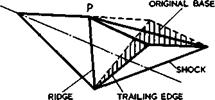
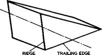
1

z(D “ /І dx = CL/C1 *

0

i. e. all wings having a given lift pass through the same point in the base plane. Of these, the one with the least drag of all is the wedge which leads to the caret wing in a threedimensional flow. If we actually need a greater cross-sectional area than that of the wedge, for the same lift, the best way of adding the extra area is by means of a ■parabolic curve. If, on the other hand, we need less area, the best policy would be to use the wedge section since this has less drag than any other and offers without penalty a bonus volume over and above our needs. What matters too, is the question of whether the volume distribution is such that the centre of gravity is in the right place so that the aircraft can be balanced and brimmed.

The same general conclusions hold in the non-linear case C2 Ф 0 . The detailed shape of the section is altered but can still be expressed analyti­cally in the form of a power law in x. The compression surface is still convex, and the effect of adding the non-linear term is to concentrate the volume further aft. Results showing the same general trends have been obtained by G J Maikapar (1966) and R S Bartlett (1966). It may seem somewhat surprising that it pays to generate a given overall lift by having a stronger shockwave, and more lift, over the front part than the corresponding wedge and then having some expansion, and taking lift off, over the rear. One might have expected that, on the contrary, a concave surface with a centred com­pression of a large number of weak waves (as in Fig. 3.10, leading to the

Townend intake surface in Fig. 3.11) should be more efficient than the wedge flow with one shock (as in Fig. 3.8, leading to the caret wing in Fig. 3.9).

That this is not so may be explained by a more detailed consideration of the

final downward deflection of the captured mass of air, which is needed to generate a given lift force; the smaller the mass of air captured and the larger the downwash imparted to it, the higher will be the drag force for a given lift.

To obtain reliable answers requires a good theory, and there are some doubts as to whether any of the approximations used above are sufficiently accurate. But to treat even the twodimensional flow with any greater accuracy than this would be a formidable task. Again, we should bear in mind that the general conclusions may be quite different when propulsion is included and considera­tion given to energy addition to a captured airstream, which will affect lift and thrust and drag as well as volume and trim.

All the bodies discussed so far were assumed to have a streamwise upper sur­face and hence a certain base area. Such a base is not likely to be accept­able in a real aircraft design, so that means must be found to eliminate it. Again, the inclusion of propulsion provides a natural means for this purpose (see section 8.6). Here, we describe some ways of how this purpose may be achieved by shaping the upper surface.

A very simple way of modifying a caret wing to have no base area but a sharp tra-Lling edge is illustrated in Fig. 8.8(a). The lower edge of the original base is the new trailing edge, so that the flow over the compression surface remains unaltered. The front part of the upper surface is still streamwise, but then two swept ridge lines from a point P to the wing tips are incor­porated and two sloping plane surfaces from these ridge lines to the new trailing edge. Such an afterbody shape was first proposed by A A Griffith

(1956) , with a view to achieving a low afterbody drag. In principle, there could be a Prandtl-Meyer expansion around the ridge lines, which directs the flow inwards towards the plane of symmetry. To turn it back into the main­stream direction could involve a useful, and possibly drag-reducing, recom­pression process. This recompression could be continuous, and L R Fowell (1955) has given a criterion for the maximum deflection angle below which the compression should be shockless. The criterion itself has been questioned by В M Bulakh (1958), but there is agreement that there should be a shockwave if the deflection angle is an ‘over expansion’ exceeds some value. What happens in a real flow has been investigated by D A Treadgold (1960) on a simplified model illustrated in Fig. 8.8(b). There are again two ridge lines behind a

Design of lifting bodies from known flowfields

(a) MODIFIED CARET WING

Design of lifting bodies from known flowfields

(b) BODY TESTED BY PIERCE « TREADGOLD

Fig. 8.8 Afterbody shapes downstream of ridge lines.

streamwise forebody of constant chord, to give the same Mach number and boundary-layer conditions along the ridges. The ridge lines are nominally near-sonic, i. e. the Mach number component normal to the ridge is near unity. The afterbody is a single plane surface sloping down at an angle of 23° relative to the forebody. Typical experimental flow patterns are given in Fig. 8.9, where the left-hand side shows limiting streamlines in the surface and the right-hand side an interpretation of the flow, based in part on

Waverider Aircraft

Design of lifting bodies from known flowfields

LINE

Fig. 8.9 Flow pattern over body of Fig. 8.8(b). After Treadgold

observations using a conical shadowgraph technique developed by D Pierce &

D A Treadgold (1964) (see also V N Alekseev & A L Gonor (1974)). We find that there is indeed a Prandtl-Meyer expansion around the ridges; when the ridges are nominally supersonic, the measured pressures agree remarkably closely with calculated values (note that linearised theory would wrongly predict a suction that tends to infinity as //a, where n is the distance normal to a sonic ridge line). This close agreement is the more remarkable since there is a clearly-visible upstream influence in the boundary layer such that the stream­lines in the surface begin to turn well before the ridge line is reached. Downstream of the ridge line, the viscous flow, subjected to a strong adverse pressure gradient, turns into a separation line well before it reaches the centre line. The flow is not conical about the apex of the afterbody. Since the separation line is highly swept, the resulting separation surface is a vortex sheet, as described in section 2.4, Fig. 2.12. Inboard of the separa­tion line, the viscous flow drawn into the core of the vortex sheet is actually directed outwards, away from the attachment line which is associated with the vortex sheet. The attachment surface divides the air which is drawn into the vortex core from that which is not and forms a nearly-parallel stream near the centre line. The inviscid external stream follows a quite different pattern: it is always directed inwards, and the turning is achieved mainly through a shockwave which is situated above the vortex sheet. Thus we have a fundamental flow pattern, where changes in the direction of the flow are required, and where these are achieved in different ways in the viscous region and in the inviscid region. With afterbodies of this kind, the drag is not likely to be low and the designer of an aircraft cannot be expected to use them, but we shall meet similar types of flow again when we discuss off-design conditions in section 8.3.

We can infer from this that we must look for other and less simple types of flow if we want to shape the upper surface of waverider aircraft, possibly with the aim of making the upper surface also contribute to the lift. The streamline-tracing technique from known flowfields can again be used so as to preserve the calculable nature of the flow. The simple expansion surface of J W Flower (1963), based on the twodimensional Prandtl-Meyer expansion has already been described in section 3.4, Fig. 3.12. The construction of Flower’s expansion surface necessarily implies that the keel is directed downwards from the mainstream direction and that the leading edges must lie in a Mach plane whose inclination is о = sin”l(l/Mg) , i. e. they are directed upwards if they are swept back. These features introduce a matching problem if such an expansion surface is to be joined onto a compression surface. For example, the leading edges of the expansion surface, which have dihedral, can­not be joined to the leading edges of a caret compression surface, which have anhedral. Flower has pointed out that his expansion surface can be joined more readily onto two or three caret surfaces so that the complete configura­tions have cross sections in the form of a Y or an X. But this may introduce large surface areas and hence friction losses. It is, therefore, worthwhile to generalise the approach, and to turn away from twodimensional to axisymmetric flowfields as a basis.

Suitable streamsurfaces, which are relatively flat, may be found in the flow – field over the tapering rear end of a body of revolution, as described by К C Moore (1965) and J G Jones et at. (1968). The most promising technique employs an ingenious idea by J Pike (1966): two axisymmetric expansion flows are placed side by side in such a way that their Mach cones intersect. A streamsurface can be drawn which starts upstream of the expansion regions and is initially parallel to the mainflow. As soon as it enters either expansion region it curves inwards. Any interaction between the two fields can be prevented by placing a vertical fin surface between them. The overall geo­metry can be chosen in such a way that the two sides of the fin surface also conform to streamsurfaces of the two flows. The particular advantage of this method lies in the fact that volume may be selectively removed from mid­semispan positions and remain concentrated near the middle. The resulting volume distribution may help to solve the ‘packaging problem’ which is typical of hypersonic aircraft, where items requiring relatively large volumes must be stowed away.

To see the design of lifting expansion surfaces in perspective, we must remember two aspects. One is that the lift generated by suction can never be a large portion of the overall lift and will decrease with increasing Mach number, simply because vacuum conditions may be reached and set a limit to it, as has been discussed already in section 6.4 in connection with Fig. 6.38.

The other is the difficulty that the expanded flow must be compressed again somehow somewhere near the trailing edge which is likely to be unswept. For example, the streamlines over Flower’s surface are straight in planview and no recompression takes place over the surface. A shockwave at the trailing edge might then bring the pressure and the flow direction back to mainstream conditions, but this will introduce the familiar shockwave/boundary-layer interaction problem. It is possible that the upstream influence of the shock­wave in the boundary layer may reach quite a long way upstream and that strong shocks may cause a bubble separation, which induces positive pressures over the surface that counteract or even reverse part of the suction produced by the expansion. Not much is known about this effect and about what would be a reasonable course to take in aircraft design. It is clear, however, that the emphasis in the aerodynamic design of hypersonic aircraft should be on the design of the compression surface.

WAVERIDER AIRCRAFT

8.1 The waverider concept and its possible applications. We shall now dis­cuss the aerodynamics of a type of aircraft which as yet exists only in our minds. The technology for building it has not yet been developed. Therefore, we cannot carry out a simple performance analysis, as we did before with other types of aircraft, to determine the types of flow and the kind of aircraft shape we should investigate before going into details. We must find some other criteria to direct us towards some definite aims. This lead can be provided by the social motivation of aviation and by some fundamental know­ledge in fluid mechanics, which has been worked out during the last century.

We have already pointed out in Chapter 1.3 (see also P L Roe (1972)) that, in all the history of travel, we may observe two constants which, because they concern human nature, may confidently be extrapolated into the future. One of these is the significance of personal contact between people, and the other is the reluctance of most people to undertake frequently journeys which last for more than a few hours. Regardless of how any of us personally regards the prospect of a "global village" in which all men are members of a truly inter­national society, it does seem very probable that this is the eventual destiny that a peaceful earth must tend toward. But this cannot come about until all major cities and centres of population are brought within a few hours of each other: the means of travel must grow to embrace the globe. To do this in a way which suits human nature is the contribution that aviation can make, and this must be our ultimate aim.

Following P L Roe (1972), we may think in terms of regions which will have to be brought within reach of convenient travel. We may suppose that the number of journeys people will wish to make from one region to another depends in some way on the number of "attractions" to be found in the other region, such as trading centres, political capitals, mineral wealth, holiday resorts, or just "people" and "places" they would like to meet and to see. If we suppose that the attractiveness of a region is simply proportional to its area, then the requirement for journeys over a distance R is

J(R) = sin (irR/R ) , (8.1)

g

for a spherical earth, where Rg = 20000km is the "global range". Very roughly, the actual distribution of population in large cities, shown in Fig.

1.5, looks like that, with a secondary peak at short ranges in the already developed regions and a maximum for the potentially most heavily used trans­port routes at about one quarter of the way around the globe. This is a striking enough conclusion, and we may expect that the actual transport requirement will, in time, approach something like that given by (8.1).

If we now add the condition that the journey time should not exceed about 2 hours, say, we find that the existing types of aircraft, which we have dis­cussed so far, cannot do the job. A slender aircraft flying at Мд m 2 would take more than twice that time to get one quarter of the way around the globe, and a high-subsonic swept-winged aircraft would take 8 to 10 hours or

more (see (1.13)). What we are looking for, therefore, is an aircraft that can fly at least at a Mach number between 4 and 5 and can speed up to Mach numbers between 8 and 12, say, to cover the full global range in good time. This, then, gives us a starting point: we cannot be satisfied with the types of aircraft we have got – we have to think out and develop at least one further type, if we take our responsibilities towards probable long-term transport needs seriously.

But could existing types of aircraft even achieve half a global range? The estimates given in Fig. 1.3 indicate: yes, but only just. We can now supplement these results by applying the aerodynamics of swept and of slender aircraft derived in previous chapters in a way which will give us some overall view of the comparative capabilities of these types of aircraft and, at the same time, chart out where we should look for a new type. To do this

in a simple way, we use the Br£guet equation (1.7) for the range and assume

some modest values on present technology for the combined propulsive aero­dynamic efficiency TipL/D such as ЛрЬ/D «3 at Mq = 2 for swept aircraft, in accordance with the results in Fig. 4.9. We also assume that aircraft can be designed to have a reasonable payload fraction when the fuel fraction is Wf/W ■ 0.45 and when the fuel is kerosene. As before (see e. g. Fig. 4.76), we describe the geometry of the aircraft simply by the box size, s/I, into

which it can be fitted. In a diagram with s/i and Mq as axes as in Fig.

8.1, lines along which R/Rg reaches certain values can then be drawn. This diagram can be subdivided into regions by three other lines which have some aerodynamic significance: a line along s/fi – 0.2 is meant to indicate that aircraft below it will be inadequate on the airfield; a line at Mo “ 1 indicates sonic speed but has no longer the significance of a "barrier"; a line along which $s/& ■ 1 indicates where a delta wing has a nominally sonio teading edget which has a greater general significance. The results in Fig, 8.1 show that the main regions of application of swept and of slender aircraft fall quite neatly into the sub-divisions of the diagram. Swept air­craft could achieve R/Rg = 0.5 but would take too long a flight time. If we impose a time limit, then we should regard high-subsonic or low-supersonic

WAVERIDER AIRCRAFT

Fig. 8.1 BrAguet ranges for various types of aircraft

LIVE GRAPH

Click here to view

swept aircraft as best suited for ranges up to between 2000km and 3000km; a range of about 5000km could be achieved in good time if we could entertain the idea of designing a swept aircraft to fly at Mq = 2 . Slender aircraft cannot quite achieve R/Rg =0.5 ; their peak turns out to lie underneath the "groundline" s/l = 0.2 , as it were, and only the application of powered lift on a big scale, as originally proposed by A A Griffith (1954, unpub­lished), could make this realisable in aircraft. Slender wings are obviously best suited for transatlantic and intercontinental ranges at Mach numbers around 2. All these existing types of aircraft lie clearly to the left of the line gs/H. = 1 .

This leads us to search for a new type of aircraft in the region to the right of the line &s/l = 1 and above the line s/l = 0.2 , and this, in turn, must bring in a new type of flow. Any aircraft shapes in that region can no longer cause only small disturbances in the air; we must now consider shapes which produce strong shockuaves in the flowfield and find means for applying these usefully. We can expect that these strong disturbances will be caused by the means for generating lift and also by the means for providing volume and propulsion. P L Roe (1972) has developed a line of basic arguments which leads to the conclusion that the part of the aircraft that provides volume should be integrated with the propulsion system and also with the lifting system, i. e. we should deal with the concept of an aerodynamically integrated propulsive lifting body. This implies that the flowfields to be considered represent the combined effects of all three means together, not the super­position of various effects of separate means with an essentially small amount of "interference" between them.

Another condition, which we are not prepared to renounce, is that the new type of aircraft should be able to fly well at low speeds and be capable of taking-off and landing, preferably without a change in its geometry. We know of only two types of flow which will allow this: one is the classical aero­foil flow, and the associated shapes are clearly unsuitable for flight in the Mach number range envisaged; the other is the slender-wing flow, and in this

case we can expect that the associated shapes might be suitable. We may,

therefore, try to find shapes which behave at low speeds like the slender wings we already know. Thus we can state at once that we want to consider shapes with aerodynamically sharp edges and near-triangular planform with a semispan-to-length ratio of about 1/4 (i. e. not below about 1/5 and not above about 1/2). In cruising flight, the leading edges will be nominally super­sonic, as defined in section 6.3, equation (6.37).

These general features imply that we do not expect to find shapes which can have the same type of flow throughout the whole flight range. The aircraft with a given value of s/i will have to pass the lines Mq = 1 and

6s/A = 1 and back again. This change in the type of flow is an important

departure from previous practice, and we must prepare ourselves to cope with such changes. We can at least demand from the outset that they should be gradual and controllable.

We have already discussed in general terms how lift can be generated at high Mach numbers by a thick body (see section 3.4, Fig. 3.9) and how thrust can be generated in flow cycles with heat addition (see section 3.6, Fig. 3.16).

We have also indicated that liquid hydrogen might be a suitable fuel for high-speed flight (see Chapter 1.2), and we assume now that this will be applied. These elements can then be combined to derive a complete aircraft. The shapes to be considered are described by the generic term "waverider" because at some design condition, a shockwave may be contained between the leading edges below the body. Anticipating results to be derived below, we can draw some lines in Fig. 8.1 for ranges which may be achieved by wave- riders, again on the assumption that an aircraft with reasonable payload can be constructed when the fuel fraction Wp/W =0.45 . Such estimates may not be very reliable, at the present state of knowledge, but they can give us a first overall view and a crude map of what lies before us (see e. g.

D KUchemann (1965), J Seddon and A Spence (1968), D Ktlchemann & J Weber

(1968) ).

The estimates in Fig. 8.1 show that the waverider aircraft of interest, which we should investigate further, all lie sensibly to the right of the line gs/£ = 1 . These shapes are aerodynamically non-slender and they are thus quite distinct from the others. The new aerodynamics and the use of hydrogen fuel dramatically increase the range beyond that of existing types of air­craft, to cover half to full global ranges within the time limit we set our­selves. This implies that the flight Mach numbers of interest lie between about 4 and about 12. It does not seem worthwhile to go further and faster.

A more detailed analysis by D H Feckham & L F Crabtree (1967) has come to the same general conclusions. They assumed a more realistic flight path, with a climb at a constant acceleration of 0.2g, then a cruise phase at a constant Mach number, and finally descent along a glide path. For the ranges and Mach numbers considered here, they find that there is a substantial phase of cruising flight within the atmosphere left, i. e. we are dealing with an ordinary aircraft again, not with a boost-glide vehicle which does not cruise and might leave the atmosphere. This distinguishes the waverider aircraft to be discussed also from any of the various space vehicles, although, as it happens, the shapes to be considered may also be suitable for space shuttle orbiters, as shown by L H Townend (1972) (see also L C Squire (1975)).

This restriction to aircraft flying in the atmosphere at Mach numbers below about 12 allows us to leave aside, on the whole, any matters associated with rarefied gasdynamics or real-gas effects in flows (for a discussion of condi­tions when such effects may arise, see e. g. W Wuest (1970), (1973), and

(1975) ). We shall be concerned again with continuum gasdynamics in the ordinary sense and discuss inviscid compressible flows as well as some vis­cous interactions, but not the chemical reactions which go together with heat addition to air flows. Thus, even though we deal with a hypothetical new type of aircraft, we can build on much basic knowledge which has been avail­able for a long time and apply results which have been found by men like W J M Rankine (1870), E Mach & P Salcher (1887), H Hugoniot (1885) (1887) (1889), D L Chapman (1899), E Jouguet (1905) (1906), L Prandtl (1907), and Th Meyer (1908). A possible waverider aircraft may bring their work to some technological application. This means that, strictly, we are concerned with supersonic flows past bodies which cause strong perturbations, where the air can be treated as a continuum substance in thermodynamic equilibrium. Some use the term hypersonic to describe such high-speed flows, and the waveriders to be discussed would then be hypersonic aircraft.

The aerodynamic background information we need to deal with these flows can be found in many textbooks, and we mention here those by R Courant &

К 0 Friedrichs (1948) H W Liepmann & A Roshko (1957), R N Cox & L F Crabtree

(1965) , and W D Hayes & R F Probstein (1966).

Design considerations

One design problem is to find a compact layout, as in Fig. 7.2, where the passenger cabin can he fitted properly into a wing of given planform. A parameter which may be used to characterise this aspect is N/S, where N is the number of passengers to be carried and S the wing plan area. We also make the assumption that the plan area of the cabin is related to the number of passengers, e. g. by Sc = 0.7N[m^] . This passenger density can be determined from (7.5) for given values of the wing loading. It turns out that, since Wp/W reaches maximum values at certain values of W/S, it also reaches maximum values at certain values of N/S, i. e. it is not worthwhile to make N/S as large as possible. The optimum values of N/S lie between about 0.6/m^ and 0.8/m^, depending on the value of the specific structure weight factor ui^ , Lighter structures allow a lower passenger density. Again, the maximum of Wp/W is very flat, and, if the optimum values of N/S should be too large for practical purposes, some departure from them need not result in a large payload penalty. Practicable values of N/S may lie below the optimum values, between 0.5/m^ and 0.6/m^. The wing loading must then be adjusted accordingly to slightly lower values than the optimum values in Fig. 7.4. It should thus be possible to find a satisfactory solution to the layout problem. The design of the cabin itself is then mainly a structural problem.

The balancing problem is closely related to the layout problem. It should be somewhat easier than that for a slender supersonic aircraft. Again, the fore – and-aft position of the engines may be used to balance the aircraft about the position of the low-speed aerodynamic centre.

Equation (7.5) can also be used to work out how the payload fraction depends on the value of the effective aspect ratio A/K , for different passenger

densities and structure weights. All the results show the same trend: a slight improvement as A/К is increased, and a levelling out and no further improvement beyond about A/K = 2 . We draw from this the important conclu­sion that the values of A/К of interest lie between about 0.5 and 2, i. e. the values of s/l lie roughly between 0.25 and 0.5. This is a belated justification of the assumption made at the beginning: that we are dealing with slender wings. Thus the various design limitations of the allwing aero – bus lead again to a region of no conflict, like that for supersonic slender aircraft in Fig. 6.72, but this region is now larger since the supersonic cruise restriction has been removed.

It is still beneficial to achieve values towards the higher end of the A/K – range: this will allow lower wing loadings and lower CL-values on the airfield, and also lower take-off thrusts. But, again, it is not worthwhile to strive to go beyond about A/K = 2 . In the aerodynamic design, therefore, the methods discussed in Chapter 6 can be applied again. In particular, the information in sections 6.5, 6.6, and 6.9 can be used, with the main data on lift, drag, and stability in Figs. 6.48, 6.49, and 6.51. The warped wing in Fig. 6.58 was designed with an application to an allwing aerobus in mind.

As yet, no such aircraft has been fully designed and built; but there is no doubt that the early studies of S В Gates and G H Lee were on the right lines. Much more work needs to be done on all aspects of the design to establish the usefulness of the concept more firmly. But the available information indicates that the prospects are promising and that a slender allwing aerobus could use­fully fill a gap in the range of air transports.

Performance considerations

To obtain a first rough survey of the poss­ible performance of this type of aircraft and of the main propulsion and structural aspects, we shall adapt the simple first-order performance analysis of section 4.1 for the present purpose and change some of the assumptions to make them more suitable for short-range aircraft. But it should be clear from the outset that some of the concepts used before, such as the Brdguet range, tend to become inadequate for flight over short ranges (see e. g. D H Peckham

(1974) ). We illustrate this by quoting first some results from an analytical treatment of the performance of short-range aircraft by S В Gates (1965), which brings out clearly those parameters that really matter and can provide a sense of direction to other numerical work. In this analysis, the basic assumptions are: the flight path consists of a climb, followed by cruise at constant speed and height, followed by a descent, and it is always below the tropopause; the slope of the path is small so that its square, and thus the curvature of the path, may be neglected; as a first approximation, the weight is constant, and so the lift is equal to the weight throughout; the fuel used, though neglected as a fraction of the weight, is itself a vital part of the economy of the short-range service; and finally, the Mach number never exceeds the critical value, and so the drag coefficient remains essentially constant.

The motion of the aircraft is then governed by (6.7) which can be written as

an equation for the flight path


Подпись: (7.1)

Подпись: Ж (h * ^ ' L7D
Подпись: ds V dh dh/dt

where t is the time. The engine thrust Th can be put equal to the sea – level thrust times a function of the density p(h) and the flight speed V. The lift-to-drag ratio is a function of Cl. The distance travelled and the time this takes can then be worked out, as well as the fuel used, if the specific fuel consumption of the engine is known.

The main conclusions from Gates’ analysis for flights over ranges of about 400km and of about 30 to 50 minutes duration are as follows:

(1) It seems probable that the installed thrust will be fixed by the airfield ;performance. The latter is also important with regard to the time spent on the airfield, which may be as much as one-third of the total time of flight.

(2) Once the aircraft has taken off, two broad alternatives for the flight ■path are open:

(a) Level acceleration near the ground to some high speed, which is then held constant for the rest of the flight. The flight time is constant on all such paths, and height can be used to economise fuel.

(b) Level acceleration near the ground to some speed less than the con­stant speed of case (a), followed by the rest of the flight at a speed which increases with height. A simple and practical example of this alternative is flight at constant JpV^ or constant equivalent airspeed. In all such paths, the time is a minimum when the whole flight is spent on climb and descent, and it is likely that this condition minimises the fuel as well. Typical examples of this kind are illustrated in Fig. 7.3.

Work of this nature is by no means complete and further studies should lead to firmer conclusions. In particular, existing methods for estimating in more detail take-off and landing manoeuvres could be applied (see e. g. D H Perry

(1969) and (1970) and R F A Keating (1974)), as well as multivariate analysis (see e. g. D L I Kirkpatrick & Joan Collingbourne (1973) and D L I Kirkpatrick (1974)) to obtain refined numerical answers under realistic constraints. But the general trends are reasonably clear and have been supported by the studies of G H Lee (1965). We note, in particular, that it pays to fly fast (at Mo = 0.8, say) and to fly high (at h = 6km, say), even over short ranges.

We can now consider some aspects of the engineering feasibility of the slender allwing concept and carry out a performance analysis and weight breakdown like that described in sections 4.1 and 6.2 but adapt it to the present purpose.

The various weight items, which add up to the given all-up weight, are now:

wuc

= 0.05W

undercarriage

w

S

= 0.05W

services and equipment

w

p

payload

WFU

= 0.5W

p

furnishings etc.

WF

fuel used

WR = 0.1W

reserve fuel

WE

installed engine

ww

wing, including cabin

Performance considerations

This list is largely the same as that for the supersonic slender aircraft in section 6.2, except that the weight of the furnishings has been reduced to indicate that less comfort might be provided in a short-range aerobus service

by (4.3). This assumes that the range R is given by BrAguet’s relation (1.7), which cannot be correct for flight paths like those in Fig. 7.3, but the error introduced by this in the weight analysis is not large, because the fuel fraction will generally turn out to be small. In the numerical examples below, we put R – 600km, i. e. between the values mentioned above. The

propulsive efficiency in subsonic flight is taken to be well below that at supersonic speeds, at rip = 0.25 . Other numerical values are Cdf = 0.0065 for the zero-lift drag coefficient, which is the same as that used in section 6.2; and A/K = 1 , which may be interpreted as implying a value of A near

1.5, or s/A near 0.35, and К = 1.5 . The maximum value of L/D is then about 11, which is consistent with the curve shown in Fig. 7.1.

Подпись: Th a W Performance considerations Подпись: (7.4)

The main change, the effect of which we want to demonstrate, is that the thrust and weight of the engine are to be determined from airfield rather than oruise considerations. Thus (6.5) is not now used. On the airfield, (6.6) and (6.8) still apply, and we note here that the factor 0.3 in (6.6) may be rather high and could possibly be lower for turbofan engines of high bypass ratio. It remains to find a relation for the thrust-to-weight ratio Tha/W for a prescribed field length. One that is suitable for our purpose has been derived by G H Lee (1965);

(see also D KUchemann & J Weber (1966)). Here, 6a is the climb angle and X is a parameter proportional to the field length; a typical value of X – lOkN/m^ corresponds to a relatively short runway of about 1400m length up to lift-off. A remarkable feature of this relation is that Tha/W depends only on the square root of the term (W/S)/(A/K) .

Подпись: W _E = W Performance considerations Подпись: - 0.3 Performance considerations Подпись: (7.5)

The various weight items can now be put together and the payload fraction determined:

We note first of all that, in contrast to the corresponding equation (4.10) for the classical aircraft, the parameter n appears in (7.5) only in the last term (fuel used). Hence, the question of finding an optimum value of n is now trivial: the largest payload fraction is obtained when n = 1 or nearly 1 (depending on how К varies with C^), i. e. when the aircraft flies near a CL~value which corresponds to the maximum of L/D, as assumed in Fig. 7.1.

We note further that the aspect ratio appears in such a way that the payload increases with increasing A/K. But the wing loading W/S now appears in two terms which oppose each other. They arise from the wing weight, which decreases with increasing wing loading, and from the engine weight, which increases.

There are several ways to determine the value of the wing loading which gives the highest payload fraction. If (7.5) is used directly without further con­straints, assuming n = 1 , an optimum value of W/S can be calculated and

Подпись: W S Подпись: (7.6)
Performance considerations

turns out to be

For the set of numerical values used above, the optimum values of W/S lie between 1 and 2kN/m^ and the corresponding payload fraction is about 0.3. But flying at the Ci/-value where L/D has its maximum, which this optimisation procedure implies, may lead to excessive cruising heights, even above the tropopause. This would not be consistent with very short ranges and might require engines with more thrust and weight than were needed for the airfield performance.

A constrained, and more realistic, optimum wing loading. is obtained if we postulate that the aircraft should cruise at Mcr =0.8 at a constant height h = 6km, so that qcr = 21kN/m^ also remains constant. The aircraft cannot then fly at the maximum value of L/D , and the fuel used will vary with the wing loading. The fuel fraction is given by the last term in (7.5), which can be rewritten in the form

R 1

R / °DF 1 c

(7.7)

Hr) (L/D)

‘p 4 ‘cr

%VCLcr ^ Lcr/

9

where

г _ W/S

Lcr q * 4cr

(7.8)

This can be inserted into (7.5) for the payload fraction, where the wing loading now appears in two further terms which again oppose each other. The optimum payload and wing loading must now be determined numerically. With the numbers used before, a typical weight breakdown is shown in Fig. 7.4, where the values of W/S which give the optimum payload are marked. According to this, the payload may Ъе as high as 30% of the all-ыр weight and thus better than that of corresponding aircraft of the classical type (see e. g. Figs. 4.3 and 4.4): a well-designed allwing aerobus presents a worthwhile target!

The constrained optimum payload is only slightly less than that corresponding to (7.6). We note further that the payload varies only little on either side of the optimum values of W/S so that there is quite some latitude in the choice of W/S, which may be used to satisfy other design requirements.

Fig. 7.4 also illustrates once more the incentive to reduce the other weight items, such as furnishings, to improve the economics. Again, an air-traffic control system which would allow a reduction of the reserve fuel would bring a worthwhile increase in payload.

In one of the examples in Fig. 7.4, the optimum wing loading is W/S = 2.8kN/m^. The thrust-to-weight ratio at take-off is then Tha/W = 0.56 , by (7.4). This is rather high, and implies that a high level of engine noise must be expected while the aircraft is on the runway. A longer runway than that assumed here would reduce Tha/W and hence the noise. But the engine may be throttled back after take-off. For example, (6.7) gives a climb-out speed Va = 95m/s at an angle 6a = 3° and CLa = 0.5 for Tha/W =0.22 . This reduction, together with the noise-shielding effects discussed in section 5.9, should make the allwing aerobus a quiet aircraft in flight.

LIVE GRAPH

Click here to view

Performance considerations

Fig. 7.4 Weight breakdown of a family of slender allwing aircraft

SLENDER AIRCRAFT FOR FLIGHT AT SUBSONIC. SPEEDS OVER SHORT RANGES

7.1 Gates1 concept of an aerobus. Most of the design problems discussed so far have been concerned with aircraft to fly over medium or long ranges, like the transatlantic range. Yet we have argued in Chapter 1 (see Fig. 1.7) that there is also a short-haul transportation gap to be filled by aircraft, when these take over from road and rail transport at distances beyond 300km or 500km. A typical short-haul operation may be a sortie of 2 x 400km without refuelling at the stop in between.

LIVE GRAPH

Подпись:Click here to view

Short-haul transport makes special demands: above all it must be cheap; and high technical standards as well as reliability, leading to high utilisation and low maintenance costs, can contribute to making it cheap, (see e. g.

A L Courtney (1965) and R H Whitby (1965), H Ziegler (1972)). Further, short – haul as compared with long-haul transport is special in that the actual door – to-door travel time may be substantially longer than the flight time owing to surface travel and airport processing, apart from any airborne or ground delays (see e. g. F R Steven (1973)). For these reasons, various attempts are made to design specialised aircraft for the purpose and to devise some integrated transport system. Technical solutions include helicopters and air­craft that can take-off and land vertically. We do not discuss these here but concentrate on one possible concept which has been proposed by S В Gates

(1960) , (1964) and (1965) (see also H H В M Thomas & D Rttchemann (1974)).

Gates had the social aspects of long-term developments in aviation foremost in mind. He wanted air transport expanded from a special service for only a small number of people to a utility service for everybody: his aerobus was to provide cheap wraps for air travellers. Although Gates’s ideas caught the imagination of many so that ‘airbus’ is now a household word, the present air­craft to which the name airbus has been given do not strictly conform to what Gates had in mind. His much more radical proposals still remain to be deve­loped and put into practice. For our purpose here, Gates’s aerobus provides an instructive example of the possibilities of aerodynamic design.

Gates argued that Cayley’s concept does not necessarily lead to the only possible layout within a given set of aerodynamics. He proposed to discard the fuselage, as a non-lifting parasite, whose structural virtues are often cancelled in a conventional layout anyway, and consider once again allwing aircraft. An "aeroplane consisting of one wing, which would house all compo­nents, engines, crew, passengers, fuel and framework" was, in fact, patented as early as 1910, by H Junkers, and other notable attempts to design tailless allwing aircraft have been made by G T R Hill (1926) with his Pterodactyl, by A Lippisch (1931), by J К Northrop (1940), and by Armstrong Whitworth (AW 52, 1947). All these retained unswept or swept wings of fairly high aspect ratio and none was really successful. Another more suitable layout had to be found, and a strong contender turned out to be the slender wing.

If a classical aircraft is to be designed for very short ranges, its layout will be much the same as that of a long-range aircraft, as has been shown in section 4.1. In some ways, the design may be more demanding: a wing whose aspect ratio is still high must be combined efficiently with a relatively bigger fuselage, since the payload fraction will be higher (see Figs.1.3 and 4.4); and high-lift devices may have to be more effective, if shorter runways are to be used, i. e. the problems indicated in Fig. 4.10 may be more severe.

On the other hand, the potentially high aerodynamic efficiency of such an air­craft may not be fully used: the aircraft may cruise well below the maximum value (L/D)m of the lift-to-drag ratio because the fuel fraction is relati­vely small and the engine weight matters more. To illustrate this point, the L/D-curve of a typical swept aircraft from Fig. 4.1 has been redrawn in Fig.

7.1, but with the cruise point somewhere well below (L/D)n. This L/D-value is assumed to be sufficient to achieve the required short range. This is where the slender wing comes in: such an L/D-Value can be achieved also by a slender wing at subsonic speeds. To illustrate this, the appropriate L/D – curve of a typical slender aircraft from Fig. 6.2 has been reproduced in Fig. 7.1. The slender aircraft will cruise at a lower CL~value than the classical aircraft, i. e. it will have a larger wing and a lower wing loading.

A lower wing loading was one of Gates’ early, design aims: it should make take­off and landing easier and safer. But it must be shown that the low wing loading is compatible with the other design aspects, especially with the structure and engine weights. This will be considered in section 7.2.

To fix our ideas, we may think of a slender allwing aircraft for short ranges having a compact shape like that sketched in Fig. 7.2, by comparison with a corresponding swept-winged layout, where the shading indicates the inhabited areas. The span of the allwing aircraft is significantly smaller than that of the swept aircraft, but its semispan-to-length ratio (about 0.35) may be larger than that of a slender aircraft to fly at supersonic speeds (about 0.25). The wing will have to be thick enough to house the flat3 non­cylindrical, passenger cabin, which in turn implies that the aircraft must be large enough, having, perhaps, 150 seats or more (although 100-seaters have

SLENDER AIRCRAFT FOR FLIGHT AT SUBSONIC. SPEEDS OVER SHORT RANGES

Fig. 7.2 Comparison between classical and allwing layouts

been studied and found to be not impossible). The gradual evolution of all­wing aircraft from swept wings to compact slender layouts has been described by G H Lee (1965) and supported by project studies. It was during this work, done at Handley-Page, that J В Edwards realised that, for an allwing slender aerobus, the engines could be mounted above the wing so that the engine noise would be shielded very effectively by the wing, as has already been described in section 5.9.