Category THEORETICAL AERODYNAMICS

NASA Aerofoils

A concerted effort within the National Aeronautics and Space Administration (NASA) during the 1960s and 1970s was directed toward developing practical aerofoils with two-dimensional transonic turbulent flow and improved drag divergence Mach numbers while retaining acceptable low-speed maximum lift and stall characteristics and focused on a concept referred to as the supercritical aerofoil. This distinctive aerofoil shape, based on the concept of local supersonic flow with isentropic recompression, was characterized by a large leading-edge radius, reduced curvature over the middle region of the upper surface, and substantial aft camber.

The early phase of this effort was successful in significantly extending drag-rise Mach numbers beyond those of conventional aerofoils such as the National Advisory Committee for Aeronautics (NACA) 6-series aerofoils. These early supercritical aerofoils (denoted by the SC (phase 1) prefix), however, experienced a gradual increase in drag at Mach numbers just preceding drag divergence (referred to as drag creep). This gradual buildup of drag was largely associated with an intermediate off-design second velocity peak (an acceleration of the flow over the rear upper-surface portion of the aerofoil just before the final recompression at the trailing edge) and relatively weak shock waves above the upper surface.

Improvements to these early, phase 1 aerofoils resulted in aerofoils with significantly reduced drag creep characteristics. These early, phase 1 aerofoils and the improved phase 1 aerofoils were developed before adequate theoretical analysis codes were available and resulted from iterative contour modifications during wind-tunnel testing. The process consisted of evaluating experimental pressure distributions at design and off-design conditions and physically altering the aerofoil profiles to yield the best drag characteristics over a range of experimental test conditions.

The insight gained and the design guidelines that were recognized during these early phase 1 investi­gations, together with transonic, viscous, aerofoil analysis codes developed during the same time period, resulted in the design of a matrix of family-related supercritical aerofoils (denoted by the SC (phase 2) prefix). Specific details about these profiles can be found in Reference 1.

Aerofoil Geometry

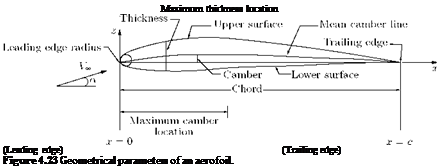
The geometrical section of a wing obtained by cutting it by a vertical plane parallel to the centerline of the aircraft is called aerofoil section. The lift generated and the stall characteristics of a wing strongly depends on the geometry of the aerofoil sections that make up the wing. The geometric parameters that dictate the aerodynamic characteristics of the aerofoil section are; the leading-edge radius, the mean camber line, the maximum thickness and the thickness distribution of the profile, and the trailing-edge angle. These parameters are shown in Figure 4.23.

4.16.1 Aerofoil Nomenclature

The tests made at Gottingen during World War I contributed significantly to the development of modern types of wing sections. Up to about World War II, most wing sections in common use were derived mostly from the work at Gottingen. During this period many families of wing sections were tested in the labora­tories of various countries, but the work of the National Advisory Committee for Aeronautics (NACA)

Подпись: Maximum thickness location (Leading edge) (Trailing edge) Figure 4.23 Geometrical parameters of an aerofoil.

was outstanding. The NACA investigations were further refined by separation of the effects of camber and thickness distribution, and the experimental work was performed at higher Reynolds number than were generally obtained elsewhere. As a result, the geometry of many aerofoil sections is uniquely defined by the NACA designation for the aerofoil.

Aerofoil geometry are usually characterized by the coordinates of the upper and lower surface. It is often summarized by a few parameters such as: maximum thickness, maximum camber, position of max thickness, position of max camber, and nose radius (see Figure 4.23). One can generate a reasonable aerofoil section given these parameters. This was done by Eastman Jacobs in the early 1930s to create a family of aerofoils known as the NACA Sections. The NACA aerofoils are aerofoil shapes for aircraft wings developed by the National Advisory Committee for Aeronautics (NACA). The shape of the NACA aerofoils is described using a series of digits following the word “NACA.”

The NACA 4-digit and 5-digit aerofoils were created by superimposing a simple mean-line shape with a thickness distribution that was obtained by fitting a couple of popular aerofoils of the time:

у = ±(t/0.2) x (0.2969×0’5 – 0.126x – 0.3537×2 + 0.2843×3 – 0.1015×4).

The camber-line of 4-digit sections was defined as a parabola from the leading edge to the position of maximum camber, then another parabola back to the trailing edge, as illustrated in Figure 4.24.

Leading edge

c

Figure 4.24 Illustration of the camber line of a 4-digit NACA aerofoil.

NACA 4-Digit Series:

The first digit implies the maximum camber in percentage of chord (c), the second digit gives the position of maximum camber in 1/10 of chord, the last two digits give the maximum thickness in percentage of chord. For example:

1. NACA 4412 aerofoil has a maximum camber of 4% of chord, with the maximum camber located at

0. 4c and thickness-to-chord ratio 12%.

2. NACA 2412 aerofoil has a maximum camber of 2% located 40% (0.4c) from the leading edge with a maximum thickness of 12% of the chord. Four-digit series aerofoils by default have maximum thickness at 30% of the chord (0.3c) from the leading edge.

3. NACA 0015 aerofoil is symmetrical, the 00 indicating that it has no camber. The 15 indicates that the aerofoil has a 15% thickness to chord length ratio: it is 15% as thick as it is long.

After the 4-digit sections came the 5-digit sections such as the famous NACA 23012. These sections had the same thickness distribution, but used a camber-line with more curvature near the nose. A cubic was faired into a straight line for the 5-digit sections.

NACA 5-Digit Series:

In NACA 5-digit series the first digit gives approximate maximum camber in percentage of chord, the second and third digits give the position of maximum camber in 2/100 of chord and the last two digits give the maximum thickness in percentage of chord. This NACA 23012 is an aerofoil with maximum camber as 2% of c, position of maximum camber at 60% of chord and t/c = 0.12.

Four – and five-digit series aerofoils can be modified with a two-digit code preceded by a hyphen in the following sequence:

1. One digit describing the roundness of the leading edge with 0 being sharp, 6 being the same as the original aerofoil, and larger values indicating a more rounded leading edge.

2. One digit describing the distance of maximum thickness from the leading edge in tens of percentage of the chord.

For example, the NACA 1234-05 is a NACA 1234 aerofoil with a sharp leading edge and maximum thickness as 50% of the chord (0.5 chords) from the leading edge.

In addition, for a more precise description of the aerofoil all numbers can be presented as decimals.

1-series:

A new approach to aerofoil design pioneered in the 1930s in which the aerofoil shape was mathematically derived from the desired lift characteristics. Prior to this, aerofoil shapes were first created and then had their characteristics measured in a wind tunnel. The 1-series aerofoils are described by five digits in the following sequence:

1. The number “1” indicating the series.

2. One digit describing the distance of the minimum pressure area in tens of percent of chord.

3. A hyphen.

4. One digit describing the lift coefficient in tenths.

5. Two digits describing the maximum thickness in percentage of chord.

For example, the NACA 16-123 aerofoil has minimum pressure 60% of the chord back with a lift coefficient of 0.1 and maximum thickness of 23% of the chord.

The 6-series of NACA aerofoils departed from this simply-defined family. These sections were generated from a more or less prescribed pressure distribution and were meant to achieve some laminar flow.

NACA 6-Digit Series:

In NACA 6-digit series the first digit refers to the series, the second digit gives the location of minimum Cp in 1/10 chord, the third digit gives the half width of low drag bucket in 1/10 of CL, the fourth digit gives the ideal CL in tenths of CL, the fifth and sixth digits give the max thickness in percentage of chord.

An improvement over 1-series aerofoils with emphasis on maximizing laminar flow. The aerofoil is described using six digits in the following sequence:

1. The number “6” indicating the series.

2. One digit describing the distance of the minimum pressure area in tens of percentage of chord.

3. The subscript digit gives the range of lift coefficient in tenths above and below the design lift coefficient in which favorable pressure gradients exist on both surfaces.

4. A hyphen.

5. One digit describing the design lift coefficient in tenths.

6. Two digits describing the maximum thickness in tens of percentage of chord.

For example, the NACA 612-315 a = 0.5 has the area of minimum pressure 10% of the chord back, maintains low drag 0.2 above and below the lift coefficient of 0.3, has a maximum thickness of 15% of the chord, and maintains laminar flow over 50% of the chord.

After the six-series sections, aerofoil design became much more specialized for the particular appli­cation. Aerofoils with good transonic performance, good maximum lift capability, very thick sections and very low drag sections are now designed for each use. Often a wing design begins with the defi­nition of several aerofoil sections and then the entire geometry is modified based on its 3-dimensional characteristics.

NACA 7-Digit Series:

Further advancement in maximizing laminar flow has been achieved by separately identifying the low pressure zones on upper and lower surfaces of the aerofoil. The aerofoil is described by seven digits in the following sequence:

1. The number “7” indicating the series.

2. One digit describing the distance of the minimum pressure area on the upper surface in tens of percentage of chord.

3. One digit describing the distance of the minimum pressure area on the lower surface in tens of percentage of chord.

4. One letter referring to a standard profile from the earlier NACA series.

5. One digit describing the lift coefficient in tenths.

6. Two digits describing the maximum thickness in tens of percentage of chord.

7. “a =” followed by a decimal number describing the fraction of chord over which laminar flow is maintained. a = 1 is the default if no value is given.

For example, the NACA 712A315 has the area of minimum pressure 10% of the chord back on the upper surface and 20% of the chord back on the lower surface, uses the standard “A” profile, has a lift coefficient of 0.3, and has a maximum thickness of 15% of the chord.

NACA 8-Digit Series:

Eight digit series profiles are supercritical aerofoils designed to independently maximize airflow above and below the wing. The numbering is identical to the 7-series aerofoils except that the sequence begins with an “8” to identify the series.

However, because of the rapid improvements in computer hardware and computer software, and because of the broad use of sophisticated numerical codes, we often encounter aerofoil sections being developed that are not described by the standard NACA geometries.

The Velocity and Pressure Distribution

For finding the velocity distribution around a given aerofoil, it is necessary to relate the angle of incidence a to the circulation Г around the aerofoil. This is done by applying the Joukowski hypothesis. In reality, the full Joukowski circulation required to bring the rear stagnation point to the trailing edge is not realized, because of the following:

• Air is a viscous fluid, and the flow near the trailing edge of an aerofoil is modified by the presence of the boundary layer and wake, caused by the viscosity.

• The zero thickness for the trailing edge, stipulated by the Joukowski hypothesis, is not possible in practice. Therefore, the trailing edge must be rounded to some degree of curvature. The finite thickness of the trailing edge owing to this rounding-off forces the rear stagnation point to deviate from the position given in the ideal case.

Therefore, if Г is the full Joukowski circulation (theoretical circulation), it can be assumed that the practical value of circulation is only кГ, where k is less than unity.

The velocity Vc, anywhere on the circle, given by Equation (4.11), is:

Knowing the distribution of Va/Vx, over the aerofoil, from Equation (4.17), the pressure coefficient around the aerofoil can be estimated.

Note that, with Equations (4.14), (4.15) and (4.17), the aerofoil shape, the velocity around it, and the Cp distribution around it can be computed, for the given values of b and e.

Example 4.5

For an aerofoil with b = 100 mm, e = 1/10 and (a) к = 1.0 and (b) к = 0.95, kept at a = 5°, determine the velocity and pressure around the transformed aerofoil.

Solution

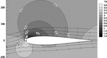
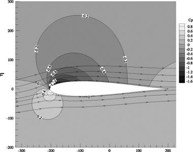
The aerofoil shape, the streamline pattern over the profile and the pressure coefficient variation around it, for the values b, e and a, listed in the problem were computed for Г = 1.0 and 0.95, with the routine given below. The results are given in Figures 4.18(a)-(d).

For Г = 1, the aerofoil shape, the streamlines and the pressure coefficient distribution around the aerofoil are shown in Figure 4.18(a). It is interesting to note that the flow leaving the aerofoil, at the trailing edge, is smooth and there is no wake, in accordance with Joukowski’s hypothesis. The Cp distribution

300 —

-300 -200 -100 0 100 200

(a)

200 –

Подпись: -400 Подпись: 0 Подпись: 200 Подпись: 300

-100

І

(b)

Figure 4.18 (a) Aerofoil shape, the streamline pattern over the profile and the pressure coefficient variation around

it, (b) Cp distribution over the aerofoil for Г = 1 and (c) the streamline pattern over the profile and the pressure coefficient variation around it, (d) Cp distribution over the aerofoil for Г = 0.95.

4

(c)

-400 -300 -200 -100 0 100 200 300

4

(d)

Figure 4.18 (Continued)

around the aerofoil, shown in Figure 4.18(b), clearly illustrates the higher pressure at the bottom and the lower pressure at the top of the profile, causing lift.

The streamlines and Cp variation around the aerofoil, for Г = 0.95 are shown in Figures 4.18(c) and 4.18(d), respectively. It is seen that, when Г is less than 1, the rear stagnation point is upstream of theAerofoil Characteristics

We saw that aerofoil is a streamlined body that would experience the largest value of lift-to-drag ratio, in a given flow, compared to any other body in the same flow. In other words, in a given flow the aerodynamic efficiency (L/D) of an aerofoil will be the maximum. When an aerofoil is exposed to a flow, due to the pres­sure acting normal to the body surface and the shear force, due to viscosity, acting tangential to the body surface, normal and tangential forces, respectively, would act on the aerofoil, as illustrated in Figure 4.19.

The pressure and shear forces can be integrated over the surface of the aerofoil to obtain the resultant aerodynamic force, Fa(j, which acts at the center of pressure (kcp) of the aerofoil.

The forces acting on an aircraft in level flight are the lift L, drag D, thrust T and weight W, as shown in Figure 4.20.

In the xz-plane or pitch plane shown in Figure 4.20, the body-oriented components are the axial forces (A), which are the forces parallel to the aircraft axis, and the normal forces (N), which are

Figure 4.19 Normal and shear forces acting on an aerofoil in a flow field.

Figure 4.20 Forces acting in the pitch (xz) plane on an aircraft.

Подпись: Figure 4.21 An aircraft in flight with lift acting ahead of cg.

perpendicular to the vehicle axis. As the aircraft travels in air, its motion is determined by its weight, the thrust produced by the engine, and the aerodynamic forces acting on the vehicle.

For a steady, unaccelerated level flight in a horizontal plane:

• The sum of the forces along the flight path is zero.

• The sum of the forces perpendicular to the flight path is zero.

When the angle of incidence a is small, the component of thrust parallel to the freestream flow direction is only slightly less than the thrust itself. Therefore, for equilibrium:

L = W T = D.

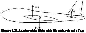
Let us consider the case where the lift generated by the wing-body configuration Lwb acts ahead of the center of gravity (cg), as shown in Figure 4.21.

The lift acting ahead of center of gravity will produce a nose-up (positive) moment about the center of gravity. The aircraft is said to be trimmed, when the sum of the moments about the cg is zero, that is:

Подпись: Y^Mcg = 0 .

Thus, a force from a control surface located aft of the cg, for example, the horizontal tail surface Lt is required to produce a nose-down (negative) pitching moment about the cg, which could balance the positive moment produced by Lwb. The tail surface producing Lt also produces a drag force which is known as the trim drag. The trim drag may vary from 0.5% to 5% of the total drag of the aircraft. It is essential to note that in addition to trim drag, the tail also produces drag due to the pressure and shear acting on its geometry, known as profile drag. Thus the trim drag is that associated with Lt generated to trim the vehicle.

In addition to the lift and drag acting in the pitch or xz-plane, there is a side force acting on the aircraft. The side force is the component of force in the direction perpendicular to both the lift and the drag. The side force acting towards the starboard (right) wing is referred to as positive.

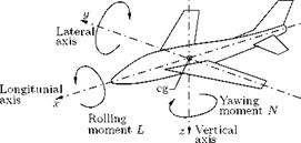
Usually the aerodynamic force will not act through the cg (which is also taken as the origin of the airplane’s axis system). The moment due to the resultant force acts at a distance from the origin may be divided into three components, referred to the airplane’s axes. The three moment components are the pitching moment M, the rolling moment L and the yawing moment N, as shown in Figure 4.22.

As illustrated in Figure 4.22: •

Pitching moment M

Figure 4.22 Illustration of pitching, rolling and yawing moments acting on an aircraft.

• Rolling moment is the moment acting about the longitudinal axis (x-axis) of the aircraft. Rolling moment is generated by a differential lift generated by the ailerons, located closer to the wingtips. Rolling moment causing the right (starboard) wingtip to move downward is regarded as positive.

• Yawing moment is the moment acting about the vertical (z-axis) of the aircraft. Yawing moment tends to rotate the aircraft nose to the right is regarded positive.

4.15.1 Parameters Governing the Aerodynamic Forces

The primary parameters governing the magnitude of the aerodynamic forces and moments are the following:

• Geometry of the aerofoil.

• Angle of attack, namely the aircraft attitude in the pitch (xz) plane relative to the flight direction.

• Vehicle size.

• Freestream velocity.

• Freestream flow density.

• Reynolds number (viscous effects).

• Mach number (compressibility effects).

The Exact Joukowski Transformation Process and Its Numerical Solution

The coordinates of the transformed aerofoil profile are obtained as follows. The transformation function can be expressed:

Comparing the real and imaginary parts, we get the coordinates of the aerofoil sections as:

Подпись: (4.15a) (4.15b) Подпись: § = x 1 + ^ 2 x2 + y2 b2

b2

x2 + y2

Referring to Figures 4.8 and 4.9, we have the distance op of point p from the origin in the z-plane, as:

op = r = be cos в + h sin в + a cos y.

The x and y coordinates of point p are:

x = a cos в’ + be y = a sin в’ + bp (1 + e).

With a = (b + be), the above coordinate expressions become:

x = (b + be) cos в’ + be, (4.16a)

Подпись: (4.16b)y = (b + be) sin в’ + be(1 + e).

where e and в represent the thickness and camber of a given aerofoil, respectively. Therefore, the values of x and y can be found for the given values of 9′, round the circle, from 0 to 2n. Substituting these x and y in to Equations (4.15a) and (4.157), the aerofoil coordinates § and n can be obtained.

This method may be used with both singularities within the circle, when:

x = a cos 9′ + be a = b (1 + e) e « 1.

The Velocity and Pressure Distributions on the Joukowski Aerofoil

The velocity anywhere on the circle with circulation in the z – plane corresponding to the lifting cambered aerofoil in the f-plane, given by Equation (4.11), is:

Vc — 2VOT [sin 0c + sin (a + 0)].

Подпись: (4.14)

The velocity Va, at the corresponding point on the aerofoil, is obtained directly by applying the velocity ratio between the transformed planes, given by:

We know that the transformation function is:

b2

Z = z + —,

z

Substituting this, further simplification can be made. The resulting equation is compact for obtaining the velocity distribution around the aerofoil profile. However, the velocity appears as square in the pressure coefficient, Cp, expression, which implies that, computing the pressure coefficient is a tedious process. The approximation that the eccentricity e is very small compared to unity (e ^ 1) progressively becomes unrealistic when thicker and more cambered aerofoil sections are required. Use of this approximation is justified only when they produce significant simplification at the expense of acceptable small deviations from the exact solutions of the velocity and pressure distributions around the aerofoil profile generated. In the present case, the utility of the approximate method largely ceases after the expressions for § and П, for the profile:

§ = 2b cos 0

П = 2be(1 + cos 0) sin 0 + 2be sin2 0.

have been obtained. For obtaining velocity and pressure distribution numerical solution may be employed.

Lift of Joukowski Aerofoil Section

Joukowski hypothesis directly relates the lift generated by a two-dimensional aerofoil to its incidence, as well as indicates the significance of the thickness to chord ratio and camber of the aerofoil in the lift generation.

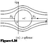
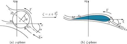
We know that, applying the Joukowski transformation, f = z + b2/z, to an offset circle, as shown in Figure 4.14(a), a cambered aerofoil shape can be obtained, as illustrated in Figure 4.14(b).

If the remaining streamlines of the flow around the circle, in the physical plane, are also transformed, they will be distorted in the transformed plane to the shape of the streamlines around the aerofoil, as shown in Figure 4.14(b).

Подпись: Figure 4.14 Подпись: c Подпись: b2 Z + — z

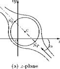
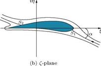
If the freestream flow approaches the circle at some angle of incidence a, as shown in Figure 4.15(a), but continue to transform about the original axes, the corresponding flow around the transformed aerofoil, in the f-plane, will be as shown in Figure 4.15(b).

Подпись: c Подпись: b2 z + — z

Streamline pattern around (a) a circle in the z-plane, and (b) an aerofoil in the f-plane.

Figure 4.15 Streamline pattern of a freestream flow at some incidence a around (a) a circle in the z-plane, and (b) the corresponding flow around the transformed aerofoil in the f-plane.

Figure 4.16 Streamline pattern of a freestream flow and circulation around (a) a circle in the z-plane, and (b) the corresponding flow around the transformed aerofoil in the f-plane.

This flow (regime) around the aerofoil is not sustained, although it is initiated every time an aerofoil starts moving from rest.

In practice, the generation of starting vortex shifts (dips) the rear stagnation point S2 to the trailing edge, that is to point M, shown in Figure 4.16(b). As the flow process develops, which takes place very quickly, the circulation around the aerofoil section is generated and the aerofoil experiences lift.

In the z-plane, the rear stagnation point S2 on the circle must have now been depressed to the correspond­ing point m to the trailing edge, as shown in Figure 4.16(a). In the transformed plane, the corresponding rear stagnation point S2 of the aerofoil is dipped to point M, as shown in Figure 4.16(b). This depression of the stagnation point enables the evaluation of the magnitude of the circulation.

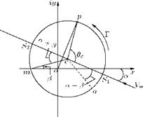
At the same time, because of the circulation Г, the forward stagnation point S1 on the circle would have been depressed by a corresponding amount to point n. The angular displacement being (a + 0), as illustrated in Figure 4.17.

In Figure 4.17, by geometry, angle subtended by ZS2cm = ZS1 cn = (a + 0). The velocity at any point p on the circle, with 0c measured from the diameter S2cSj, given by Equation (2.51), is:

Г

Vc = 2V^ sin 0c + ,

2na

Figure 4.17 Depression of stagnation points.

Подпись: CL = 2n(1 + e) sin (a + 0) . Подпись: (4.12)

Therefore,

This is the lift coefficient of a two-dimensional aerofoil, in terms of thickness to chord ratio (t/c = 1.299e), percentage camber (100 0/2), and angle of incidence a. Though this relation for CL is compact, there are severe limitations for its use, because of the following reasons:

• It has been assumed throughout that the fluid is ideal, that is, incompressible and inviscid, that is, the viscous effects are neglected, although in the real flow process creating circulation Г, and hence lift L on an aerofoil, the viscosity (^) is important.

• One of the simplest transformation functions, namely the Joukowski transformation function, has been used in the analysis. Therefore, the results are applicable only to a particular family of aerofoils.

However, this result can be of use as a reference value. Differentiation of Equation (4.12), with respect to the incidence angle a, gives the ideal lift curve slope, a(xlI.

a^I — dC l/da

= 2n(1 + e) cos (a + 0).

Подпись: a<x>I — Подпись: 2n . Подпись: (4.13)

For small values of eccentricity e, angle of incidence a and camber 0, this simplifies to:

This is the theoretical value of lift curve slope per radian of angle of attack, a. It is seen that, the lift curve slope is independent of the angle of attack.

The Kutta Condition in Aerodynamics

The Kutta condition allows an aerodynamicist to incorporate a significant effect of viscosity while ne­glecting viscous effects in the underlying conservation of momentum equation. It is important in the practical calculation of lift on a wing.

The equations of conservation of mass and conservation of momentum applied to an inviscid fluid flow, such as a potential flow, around a solid body result in an infinite number of valid solutions. One way to choose the correct solution would be to apply the viscous equations, in the form of the Navier-Stokes equations. However, these normally do not result in a closed-form solution. The Kutta condition is an alternative method of incorporating some aspects of viscous effects, while neglecting others, such as skin friction and some other boundary layer effects.

The condition can be expressed in a number of ways. One is that there cannot be an infinite change in velocity at the trailing edge. Although an inviscid fluid (a theoretical concept that does not normally exist in the everyday world) can have abrupt changes in velocity, in reality viscosity smooths out sharp velocity changes. If the trailing edge has a nonzero angle, the flow velocity there must be zero. At a cusped trailing edge, however, the velocity can be nonzero although it must still be identical above and below the aerofoil. Another formulation is that the pressure must be continuous at the trailing edge.

The Kutta condition does not apply to unsteady flow. Experimental observations show that the stag­nation point (one of two points on the surface of an aerofoil where the flow speed is zero) begins on the top surface of an aerofoil (assuming positive effective angle of attack) as flow accelerates from zero, and moves backwards as the flow accelerates. Once the initial transient effects have died out, the stagnation point is at the trailing edge as required by the Kutta condition.

Mathematically, the Kutta condition enforces a specific choice among the infinite allowed values of circulation.

The Kutta Condition Applied to Aerofoils

When a smooth symmetric body, such as a cylinder with oval cross-section, moves with zero angle of attack through a fluid it generates no lift. There are two stagnation points on the body – one at the front and the other at the back. If the oval cylinder moves with a nonzero angle of attack through the fluid there are still two stagnation points on the body – one on the underside of the cylinder, near the front edge; and the other on the topside of the cylinder, near the back edge. The circulation around this smooth cylinder is zero and no lift is generated, despite the positive angle of attack.

If an aerofoil with a sharp trailing edge begins to move with a positive angle of attack through air, the two stagnation points are initially located on the underside near the leading edge and on the topside near the trailing edge, just as with the cylinder. As the air passing the underside of the aerofoil reaches the trailing edge it must flow around the trailing edge and along the topside of the aerofoil toward the stagnation point on the topside of the aerofoil. Vortex flow occurs at the trailing edge and, because the radius of the sharp trailing edge is zero, the speed of the air around the trailing edge should be infinitely fast! Real fluids cannot move at infinite speed but they can move very fast. The very fast airspeed around the trailing edge causes strong viscous forces to act on the air adjacent to the trailing edge of the aerofoil and the result is that a strong vortex accumulates on the topside of the aerofoil, near the trailing edge. As the aerofoil begins to move, it carries this vortex, known as the starting vortex, along with it. Pioneering aerodynamicists were able to photograph starting vortices in liquids to confirm their existence.

The vorticity in the starting vortex is matched by the vorticity in the bound vortex in the aerofoil, in accordance with Kelvin’s circulation theorem. As the vorticity in the starting vortex progressively increases, the vorticity in the bound vortex also progressively increases, and causes the flow over the topside of the aerofoil to increase in speed. The stagnation point on the topside of the aerofoil moves progressively towards the trailing edge. After the aerofoil has moved only a short distance through the air, the stagnation point on the topside reaches the trailing edge and the starting vortex is cast off the aerofoil and is left behind, spinning in the air where the aerofoil left it. The starting vortex quickly dissipates due to viscous forces.

As the aerofoil continues on its way, there is a stagnation point at the trailing edge. The flow over the topside conforms to the upper surface of the aerofoil. The flow over both the topside and the underside join up at the trailing edge and leave the aerofoil traveling parallel to one another. This is known as the Kutta condition.

When an aerofoil is moving with a positive angle of attack, the starting vortex will be cast off, and the Kutta condition will be established. There will be a finite circulation of the air around the aerofoil and the aerofoil will generate lift, with magnitude equal to that given by the Kutta—Joukowski theorem.

One of the consequences of the Kutta condition is that the airflow over the upper surface of the aerofoil travels much faster than the airflow over the bottom surface. A portion of air flow which approaches the aerofoil along the stagnation streamline is split into two parts at the stagnation point, one half traveling over the upper surface and the other half traveling along the bottom surface. The flow over the topside is so much faster than the flow along the bottom that these two halves never meet again. They do not even re-join in the wake long after the aerofoil has passed. This is sometimes known as “cleavage.” There is a popular fallacy called the equal transit-time fallacy that claims the two halves rejoin at the trailing edge of the aerofoil. This fallacy is in conflict with the phenomenon of cleavage that has been understood since Martin Kutta’s discovery.

Whenever the speed or angle of attack of an aerofoil changes there is a weak starting vortex which begins to form, either above or below the trailing edge. This weak starting vortex causes the Kutta condition to be re-established for the new speed or angle of attack. As a result, the circulation around the aerofoil changes and so too does the lift in response to the changed speed or angle of attack.

The Kutta condition gives some insight into why aerofoils always have sharp trailing edges, even though this is undesirable from structural and manufacturing viewpoints. An aircraft wing with a smoothly rounded trailing edge would generate little or no lift.

J oukowski Hypothesis

Joukowski postulated that “the aerofoil generates sufficient circulation to depress the rear stagnation point from its position, in the absence of circulation, down to the sharp trailing edge.” There is sufficient evidence of a physical nature to justify this hypothesis, and the following brief description of acceleration of an aerofoil from rest may serve as a reminder. Immediately after the state of rest, the streamline pattern around the aerofoil is as shown in Figure 4.13(a).

As seen in Figure 4.13(a), immediately after starting, the rear stagnation point S2 is well ahead of the trailing edge. During the subsequent acceleration to steady motion, the rear stagnation point moves to the trailing edge, a starting vortex or initial eddy is cast off and circulation to an equal, but opposite amount, is induced in the flow around the aerofoil, as shown in Figure 4.13(b).

In the potential flow model of a sharp-edged aerofoil the exact trailing edge point can be defined, because the top and bottom profiles are cusped, at the trailing edge, resulting in zero thickness. It is essential to note that this kind of sharp trailing edge, with zero thickness, is just a mathematical shape,

iy

%n

o

x

o

(a) b = a, center at the origin

(b) b < a, center at the origin

%n

o

(c)

b = om < a, center above the origin

(d)

b = om < a, center shifted horizontally

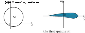
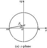
Figure 4.12 Transformation of a circle to (a) flat plate, (b) ellipse, (c) circular arc, (d) symmetrical aerofoil,

(e) cambered aerofoil.

(a)

Figure 4.13 Streamline pattern around an aerofoil (a) just after start, (b) after the starting vortex is established.

and cannot be realized in practice. Actual wing profiles are with a rounded trailing edge of finite thickness. Because of the rounded trailing edge of the wings, in actual flow where viscous boundary layer and wake exist, the position of the rear stagnation point may differ from the location predicted by potential flow theory, and the full Joukowski circulation, may not be established. This is because for realizing full Joukowski circulation, the trailing edge should be of zero thickness and without any wake. This condition of realizing full Joukowski circulation, resulting in flow without wake, is known as Kutta condition.

The Kutta condition is a principle in steady flow fluid dynamics, especially aerodynamics, that is applicable to solid bodies which have sharp corners such as the trailing edges of aerofoils. It is named after the German mathematician and aerodynamicist Martin Wilhelm Kutta.

The Kutta condition can be stated as follows:

"A body with a sharp trailing edge which is moving through a fluid will ‘create about itself a circulation’ of sufficient strength to hold the rear stagnation point at the trailing edge."

In fluid flow around a body with a sharp corner the Kutta condition refers to the flow pattern in which fluid approaches the corner from both directions, meets at the corner and then flows away from the body. None of the fluid flows around the corner remaining attached to the body.

The Kutta condition is significant when using the Kutta—Joukowski theorem to calculate the lift generated by an aerofoil. The value of circulation of the flow around the aerofoil must be that value which would cause the Kutta condition to exist.

Transformation of Circle to Circular Arc

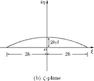
Transformation of a circle with its center shifted above (or below) the origin, on the ordinate in the z-plane, with the transformation function Z = z + b2/z results in a circular arc, as shown in Figure 4.10.

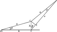
A general point p on the circle with center above the origin, on the у-axis, in Figure 4.10, can be represented as shown in Figure 4.11.

Figure 4.10 Transformation of circle to circular arc.


Figure 4.11 The point p on the circle with its center on the ordinate in the physical plane.


From Figure 4.11, it is seen that:

h = b tan в & Ьв ol = oc cos в = b в cos в lp = a cos у = (b + be) cos у

& b + be (because у is small, cos у & 1).

Therefore,

Подпись:oP r

r b

or

b -1

– = [1 + (e + в cos в)]

But, (e + в cos в) ^ 1, therefore, expanding the above, retaining only the first-order terms, we get:

b

– = 1 — e — в cos в. r

The Joukowski transformation function is:

b2

Z = z + —.

z

Replacing z = re’e, we have:

ie b2

Z = re’e + —

re

b2

= r(cos в + i sin в) +—— (cos в — i sin в)

r

b2 b2
= r cos в +—— cos в + ir sin в — i— sin в

rr

r b r b

= b —I— cos в + ib [——— sin в.

b+r b r

rb

Substituting for — and -, we get: br

Z = 2b cos в + ib(2e + 2в cos в) sin в ^ + in = 2b cos в + ib(2e + 2в cos в) sin в.

Comparing the real and imaginary parts, we get:

Подпись: 2b cos в

Подпись: 2b(e + в cos в) sin в

(4.10a)

Equations (4.10a) and (4.10ft), respectively, are the expressions for the abscissa and ordinates of the circular arc, in the transformed plane.

The chord is given by:

§ = (2b cos в) = 4b.

0 0

The camber becomes:

Подпись: в=л/2n = n

max

Подпись: в=п/2= (2b(e + в cos в) sin в)

= 2be.

But,

be

— = tan в b

e = tan в-

Therefore:

nmax = 2b tan в-

Note: In this analysis, it is essential to note that the angle в, in Figure 4.11, is marked as the angle subtended at the origin o by the line op and the ordinate. This convention is different from that followed in Figure 4.9. This change made is justified by nmax at в = n/2, which has to be satisfied.

4.9.1 Camber of Circular Arc

For the transformed circular arc, the chord is 4b. The camber is the maximum deviation of the arc line from the chord. Thus, the camber-to-chord ratio becomes:

Подпись: 2b tan в 4b Camber/chord

= – tan в – 2 в

But for small в, tan в ^ в. Therefore, the percentage camber for the circular arc becomes 100 в/2.

b2

Thus, on transformation with Z = z +—— , a circle with its origin on the y-axis, as shown in Figure

z

4.10(a), transforms to a circular arc of camber-to-chord ratio в. This is the extreme case of Joukowski profile, for which the camber is finite and the thickness is zero.

The transformation of a circle of radius a in the z-plane with its (a) center at the origin and b = a, (b) center at the origin and b < a, (c) center above the origin and b = om < a, (d) center shifted horizontally and b = om < a and (e) center in the first quadrant and b = om < a, using the Joukowski transformation, Z = z + b2/z, results in a flat plate, ellipse, circular arc, symmetrical aerofoil and cambered aerofoil, respectively, as shown in Figures 4.12(a)-4.12(e).