Our heavyweight helicopter equal in the world does not have
In Rostov started production of the most load-lifting rotary-wing car The Russian holding «Helicopt[...]

Everything about aircrafts and helicopters. News and events in aviation worldwide. Civil, transportation, military helicopters and airplanes.

Everything about aircrafts and helicopters. News and events in aviation worldwide. Civil, transportation, military helicopters and airplanes.

Everything about aircrafts and helicopters. News and events in aviation worldwide. Civil, transportation, military helicopters and airplanes.

Everything about aircrafts and helicopters. News and events in aviation worldwide. Civil, transportation, military helicopters and airplanes.


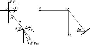
Let us consider two vortex elements with circulations Г1 and Г2, as shown in Figure 8.20. The velocity induced at ds2 by ds1 along Ox is:
Г 1ds1
du = ——- — cos в cos Ф1.
4nr2
This induced velocity is against the wind. This induces a lift in the element ds2, given by:
2 p Г1Г2
d F12 = рГ2ds2du = —- — ds1 ds2 cos в cos ■
4nr2
|
Figure 8.20 Two vortex elements. |
The velocity induced at ds1 by ds2 is with the wind, and the induced lift is:
2 p Гі Г2
d F21 = —— 7T – ds1 ds2 cos в cos ф2
4nr[14] [15]
Resolving along n, the projection of the line joining the elements on a plane normal to the wind, we get:
d2F12 cos ф2 — d2F21 cos фі = 0.
Resolving perpendicular to n, we get:
Лъ • , ,2 V ■ . P Г1Г2 ds1 ds2 „ . ,, ,4
d2 F21 sin Ф1 — d F12 sin Ф2 = ——- —— cos в sin (Ф1 — Ф2).
4nr2
This vanishes when фі = ф2 and is small in general.
Munk’s theorem of stagger states that “the total drag of a multiplane system does not change when the elements are translated parallel to the direction of the wind, provided that the circulations are left unchanged.” Thus the total induced drag depends only on the frontal aspect. To illustrate this, let us consider a lifting element of length ds1 placed at O, and another lifting element of length ds2 placed at A in a plane parallel to x = 0, as shown in Figure 8.19.
Let the circulations of the elements ds1 and ds2 are Г1 and Г2, respectively. The normal AH drawn in the plane parallel to x = 0 makes an angle ф2 with OB and:
e = Фі – I
If dwn is the induced velocity at A along AH, using Equation (8.64), we can express dwn as:
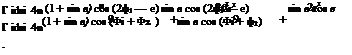 |
dwn = dv sin e + dw cos e
![]() sin в cos (Фі — ф2)
sin в cos (Фі — ф2)
2r2
If there is a flow of velocity V along xO, the drag induced by ds1 on ds2 is:
 |
To get the drag induced on ds1 by ds2 let us replace в with —в, the angle of stagger. Then:
Thus the total drag mutually induced on the pair of lifting elements becomes:
![]() p Г1Г2ds1ds2 cos (Ф1 + Ф2) 2n n2
p Г1Г2ds1ds2 cos (Ф1 + Ф2) 2n n2
which is independent of the angle of stagger. This yields Munk’s theorem of stagger, that is:
“the total drag of a multiplane system does not change when the elements are translated parallel to the direction of the wind, provided that the circulations are left unchanged."
When the system is unstaggered (that is, when в = 0):
d2D12 = d2D21
and thus if the lifting systems are in the same plane normal to the wind, the drag induced in the first by the second is equal to the drag induced in the second by the first. This result constitutes Munk’s reciprocal theorem.
The total mutual induced drag is:
![]() p Г1Г2 cos (Ф1 + Ф2) 2n n2
p Г1Г2 cos (Ф1 + Ф2) 2n n2
where Ф1 is the angle between the plane containing the normals to the element ds1 and the projection of the line joining the elements on the plane normal to the wind and ф2 is the angle between the plane containing the normals to the element ds2 and the projection of the line joining the elements on the plane normal to the wind.
Lifting surface theory is a method which treats the aerofoil as a vortex sheet over which vorticity is spread at a given rate. In other words, the aerofoil is regarded as a surface composed of lifting elements. This is different from the lifting line theory, discussed in Section 8.7. The essential difference between the lifting surface theory and lifting line theory is that in the former the aerofoil is treated as a vortex sheet, whereas in the latter, the aerofoil is represented by a straight line joining the wing tips, over which the vorticity is distributed.
8.12.1 Velocity Induced by a Lifting Line Element
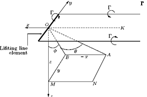
Let us consider a horseshoe vortex of infinitesimal span ds and circulation Г, as shown in Figure 8.18. The origin is at the mid-point of the span and the x-axis parallel, but opposed in sense, to the arms I, I’ of the horseshoe. Let us calculate the induced velocity at the point A (x, y, z). For this let us first consider a single semi-infinite vortex OK of circulation Г, in the same sense as the circulation about arm I. Let the velocity induced by vortex OK at A be (u,v, wj). If this vortex OK were shifted to coincide with
 |
![]()
![]()
I the induced velocity would be, by Taylor’s theorem:
because the effect on the velocity is the same as if no shift were made, and the y-coordinate of A were increased by 2ds.
![]()
The vorticity direction on arm I’ is opposite to that on arm I, therefore the velocity induced by arm I’ at A would be:
Therefore the total velocity induced at A by the pair I, I’ is:
du1 9v1 9w1
—- ds, — ds, ———- ds.
dy dy dy
Projecting A on the plane x = 0, the plane y = 0 and the z-axis we get the points B, N, M shown in Figure 8.18. Let OB = n, OA = r.
The vortex OK induces a velocity q1 perpendicular to plane OAB. Thus:
U1 = 0, v1 = —q1 cos ф, w1 = q1 sin ф,
 |
|
where by Equation (5.50):
The asymmetrical drag grading across the span, shown in Figure 8.17, gives rise to yawing moment N. The contribution of the vortex drag of an element of span dy, at a distance y from the oz-axis is:
![]() AN = dvydy,
AN = dvydy,
where dy is the vortex drag per unit span and dv = pwk. Integration over the whole span gives the yawing moment as:
![]() b pb
b pb
dvydy = I pwkydy.
b J-b
Inserting the series expressions for the circulation k and downwash w, and changing the limits and variables from Cartesian to polar, we get:
![]() Ґ У’ nAn sin ив
Ґ У’ nAn sin ив
pV—————— 4bV у An sin neb cos ebsin ede
Jo P sin в ^ n
= —4pb3V2 ^ ‘ nAn sin nQ ‘У ‘An sin пЄ cos ede.
0
The yawing moment can also be expressed as:
where CN is the yawing moment coefficient. Thus:
CN = ‘S^nAn sin nQ ‘У ‘An sin nQ cos QdQ.
0
Multiplying these series for a few terms, we can express the general solution as:
since all terms other than those with coefficients which are products of A1A2, A2A3, A3A4, etc. vanish on integration.
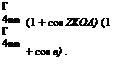
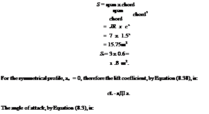
Example 8.4
A symmetrical profile of aspect ratio 7 and chord 1.5 m flying at 200 km/h at sea level is suddenly subjected to a downwash of 2.4 m/s. If the horizontal tail of span 3 m and chord 0.6 m is 5 m aft of the aerodynamic center of the profile, determine the tail deflection required to counter the pitching moment caused by the sudden downwash.
![]()
|
|
 |
|
|
|
|
|
|
|
|
|
|
|
|
Note that the pitching moment caused by the downwash is nose-down (negative). Therefore, the horizontal tail has to generate a downward lift, resulting in a pitching moment which is positive (to counter the nose – down moment). This calls for an upward deflection of the horizontal tail by 14.28°.
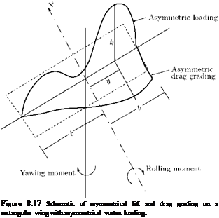 |
Let us consider a rectangular wing with an asymmetrical lift grading and the corresponding drag grading, as shown in Figure 8.17.
The lift acting on any section of spanwise length Sy at a distance y from the centerline (ox-axis) will produce a negative increment of rolling moment equal to:
ALr = —lydy, (8.59)
where l is the lift grading given by l = pVk.
The total moment becomes:
![]() b /• b
b /• b
![]() ly dy = — I pVk y dy.
ly dy = — I pVk y dy.
b J—b
Substituting k = 4bV^2 An sin uB and expressing y = b cos в, we get:
 |
||
Lr = 4pbV2 / J2
The rolling moment is also given by:
1 2
Lr = 2 pV2SCLRb,
where CLr is the rolling moment coefficient. Therefore:
![]() Lr
Lr
pV 2Sb
pb3V 2A2n 2pV2 (2b x c) b 2nA2b2 2b x c 2nA2(2b)2 4 x 2b x c n 2b
2 — A2.
2c
2b
But — = JR, therefore:
c
Following a similar procedure we used for determining the lift and vortex drag associated with symmetrical loading, we can show that:
b
L = pUkdy
 pU 4bUy~]
1 2
= 2pU 2SCl,
giving the lift coefficient as:
Cl = лАЛ!,
the same as Equation (8.20a).
8.11.1 Downwash
As given by Equation (8.18), the downwash for asymmetrical loading also becomes:
U У’ иАи sin ив
w = ——————— .
sin в
But this will no longer be symmetrical as it contains even harmonics.
8.11.2 Vortex Drag
As in the case of symmetrical loading, integrating from 1 to ж, the drag becomes:
ж
Dv — 2npb2U2 ^2 nAl-
n=1
Thus the drag coefficient becomes:
2npb 2U2J2 ж=1 nAt
2 pU2S
_ n (2b)2 A 2
(2b x c) ^ П n
n—1
Ж
= лЖ ’22nAl
n—1
— лЖ [a1 + 2A2 + 3A3 + 4A4 + 5A2 +———- ].
By Equation (8.20a), A1 — Сь/(лЖ), thus:
where:
![]() 2A2 3A3
2A2 3A3
—2 – i—— 3 •
A2 + A2 + and S > 0.
Example 8.3
A monoplane weighing 73575 N has elliptic wing of span 15 m. When it flies at 300 km/h at sea level, determine the circulation around sections half-way along the wings.
Solution
Given, W — 73575 N, 2b — 15 m, V — 300/3.6 — 83.33 m/s.
The air density at sea level is 1.225 kg/m3 and in level flight, L — W.
The lift for elliptical loading, by Equation (8.6), is:
L — pUk^n 2.
Therefore, the circulation at the mid-span becomes:
2L
k0 — —–
pUnb
2 x 73575
= 1.225 x 83.33 x n x (15/2) = 61.18m2/s.
The circulation for elliptical distribution, by Equation (8.5), is:
k=kV! – (b У.
Therefore, the circulation around sections half-way along the wings, that is, at b/4, becomes:
This is an aerofoil whose planform is a rectangle. An aerofoil whose shape is that of a cylinder erected on an aerofoil profile satisfies this requirement.
8.10.6 Cylindrical Rectangular Aerofoil
This is the simplest type, of span 2b and chord c, which is constant at all sections. All the sections are similar and similarly situated.
8.11 Aerodynamic Characteristics of Asymmetric Loading
The vortex distribution k(y) for symmetrical loading falls symmetrically about the mid-span section of an aerofoil, involving only the odd terms, and producing vortex drag and downwash variation which are also symmetrical about the centerline. In the general case, where the loading or lift distribution is not symmetrical about mid-span section, even terms appear in the distribution, and as a consequence of the asymmetry other characteristics of aerofoil appear.
When the lift distribution is not symmetrical about the centerline, one wing will have higher lift than the other. This will cause a rolling moment about the longitudinal axis passing through the mid-span of the wing.
Further, as the lift is not symmetric nor is the spanwise distribution of circulation, the downwash will vary across the span without being symmetrical about the centerline and so will be the vortex drag grading. Hence, more drag will be experienced on one wing (the one with more lift) than on the other and a net yawing moment will result about the vertical (normal) axis through the mid-span section. In addition to these there will be the overall lift and vortex drag force normal and parallel to the plane of the aerofoil in the plane of symmetry.
From Equation (8.43), we have:
![]()
|
|
|
|
|
|
|
|
|
|
|
|
|
|
|
|
|
|
|
Lift and Drag Calculation by Impulse Method
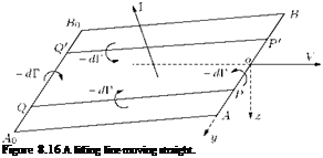 |
Let us consider an aerofoil, regarded as a lifting line AB, started from rest and which moves in a straight line. Let the velocity be V at time t. Let at time t the starting vortex be assumed to be A0B0, as shown in Figure 8.16.
Let us assume that the wake ABA0B0 remains as a rectangular sheet, as shown in Figure 8.16. If P is the point (0, y, 0) and Q is the point (-l, y,z). The flow from point P reaching the line A0 B0 experiences a circulation of – dk(y) [Equation (8.1)]. Therefore the whole wake may be regarded as resulting from the superposition of vortex rings, a typical one being PP’ QQ of circulation – dk(y).
Let PQ = h. The area of the ring is 2yh. If n is the unit normal to a small area dS separating points P and Q, the impulse on this area due to impulsive pressure is:
—npфPdS at P and + npфQdS at Q,
where:
ФQ – фp = drc = k,
where c is any circuit joining points P and Q and not intersecting the plane containing P and Q. Thus the resultant linear impulse on the system is the vector:
I = I p (фq — фP) ndS = I pkndS = pkSn.
Js J S
Thus the impulse for the area (2yh) of the vortex ring, with n as the unit normal to the plane rectangle, is:
dl = p [—dk(y)] 2yhn = pdk(y) ■ 2y (kl + iz),
since —hn = kl + iz, by geometry. The impulse I of the whole wake is:
[ 2ydk(y) = f ydk(y) = [yk(y)] + — f k(y) dy.
J OA J BA J-b
Thus:
|
/ |
+b
p (kl + iz) k(y) dy.
The time rate of change of the impulse gives the force. Therefore the aerodynamic force is dl/dt and dl/dt = V, while dz/dt = w, the normal velocity at Q, which by symmetry of the ring is equal to the downwash velocity at P. Thus the aerodynamic force is:
|
/ |
+b f‘ +b
pVk(y) dy — i pwk(y) dy,
b J —b
which consists of the same lift and induced drag as were calculated by Prandtl’s hypotheses.
The method of the impulse is applicable whatever the form of the wake.
In problem I for a given circulation k(y), the form of the aerofoil has been found. Problem II is an inverse problem in which the form of the aerofoil is known and the circulation has to be determined. To do this we must solve the integral equation [Equation (8.29)], noting that the symmetry with respect to the median plane of the aerofoil demands that k(y) = —k(y). In terms of the eccentric angle в we can therefore write the Fourier sine series, since k(y) vanishes at the tips of the aerofoil, that is at в = 0 and в = n.
TO
k(y) = 4bU ^ ‘ An sin пв. (8.42)
1
Note that n must be an odd integer to ensure the equality of sin пв and sin n(n — в). Thus:
TO
![]() k(y) = 4bU У ^ A2n+j sin (2n + 1)в.
k(y) = 4bU У ^ A2n+j sin (2n + 1)в.
n=0
This formula for k(y) is unchanged when (п — в) is written for в, and the value at the center given by в = п/2 is:
k = 4b^2A2n+1(—1)n – (8-44)
n=0
Substitution of Equation (8.43) into (8.29) gives:
![]()
![]()
b rj
> A2n+1 sin (2n + 1)в = a’———-
ТІ п J 0
^^(2n + 1)A2n+1 cos(2n + 1)фdф
n=0
b (cos ф — cos в)
At this stage it will be useful to understand the integral on the right-hand side of this equation. The integral on the right-hand side of Equation (8.45) is of the type:
|
|
![]()
where n is an integer.
In terms of its principal value, let us define In as:
|
|
![]()
This is physically equivalent to omitting the vorticity between (в — е) and (в + е) and then taking the limit е ^ 0 so that в remains the center of the omitted portion.
If n = 0 we have, by differentiation:
|
1 sin 2 (в + ф) ~^log—1————— |
|
|
|||
|
||||
|
||||
|
||||
|
||||
![]()
Hence:

![]() 1
1
І0 = !ше^0 : log
sin в
It follows that we may write:
![]()
In = In — І0 cos пв =
cos пф — cos пв
—— Г——– тгЛф.
cos ф — cos в
To find the coefficients of A2n+j in Equation (8.47), we need to expand each side, and each term on the left hand side in a Fourier series, thus leading to infinite number of equations and infinite number of unknowns. To overcome this difficulty and solve Equation (8.47), we should resort to a practical method of solution, due to Glauert.
Let us replace the infinite series of Equation (8.43) by a finite series of, say, (m + 1) terms, where m is a given integer, thus giving:
m
‘У ‘ A2n+1 [(2n + 1) + sin 0] sin (2n + 1)0 = ^gag sin 0. (8.48)
n=0
This equation cannot be satisfied identically. However, if we take a particular value of 0 we get a linear equation in the coefficients A1, A3, … A2m+1. If (m + 1) particular values are assigned to 0 we get (m + 1) linear equations from which the coefficients A2n+1 can be calculated, and the values so obtained will satisfy Equation (8.48), not identically, but only at the selected points. The solution will be satisfactory if the coefficients so determined satisfy Equation (8.48) at other points within the standard of accuracy required for any particular case.
Since Equation (8.48) is satisfied in any case when 0 = 0or n, we have (m + 1) points other than these points. The chosen points are usually taken as equally spaced in 0 over the half-span. Thus if m = 3 we should take:
п 3п п п = 2 ’ Y ’ 4 ’ 8 ’
and with these values we could determine four coefficients:
A1, A3, A5, A7. (8.49)
A rough approximation is obtained by taking m = 1, and 0 = п/2, п/4. This will determine two coefficients A), A3 but it must not be inferred that, comparing with Equation (8.49), A[ = A1, A’3 = A3.
If the incidence a0 has the same value a at each point on the span, Equation (8.47) shows that A2n+i is proportional to a, and if we write A2n+1 = a B2n+1, the coefficients B2n+1 are independent of incidence and may therefore be determined once for all.
By Equation (8.38), we have:
, CL
a = “o + ПЖ.
Also the induced drag coefficient, by Equation (8.8), is:
![]()
![]()
 |
C2
 |
|
Hence, if the aspect ratio is reduced to JR and if the ‘primes’ refer to the new aerofoil with the same incidence, we have:
Thus for a given lift curve, decrease of aspect ratio increases both the geometrical incidence and the induced drag coefficient.